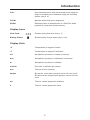
1
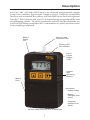
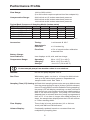
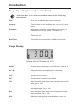
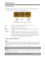
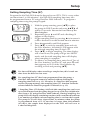
User Manual (applies to all AirChek 2000 models) SKC Inc. 863 Valley View Road Eighty Four, PA 15330 USA Form #37731—Rev 0801 Table of Contents Description....................................................................................................................................................1 Performance Profile..................................................................................................................................... 2 Introduction Pump Operating Terms (Run Time Data)............................................................................................. 4 Pump Display....................................................................................................................................... 4 Keypad Basics...................................................................................................................................... 6 Pump Operating Modes........................................................................................................................ 6 Setup Pump Activation.................................................................................................................................... 8 Verify Battery Charge........................................................................................................................... 8 Entering and Navigating the User Interface.......................................................................................... 8 Using User Interface - Level One......................................................................................................... 8 Using User Interface - Level Two......................................................................................................... 9 Resetting Run Time Data................................................................................................................... 10 Setting Pump Flow Rate..................................................................................................................... 10 Setting Sampling Time....................................................................................................................... 11 Setting a Delayed Start....................................................................................................................... 12 Deleting a Delayed Start..................................................................................................................... 12 Deleting a Sampling Time.................................................................................................................. 13 Deleting a DataTrac 2000 Program.................................................................................................... 13 Calibration Flow Rate and Volume Display.......................................................................................................... 14 Verifying Flow Rate Using a Primary Standard.................................................................................. 14 Calibrating Using CalChek................................................................................................................. 16 CalChek Error Chart........................................................................................................................... 20 Calibrating for Low Flow (5 to 500 ml/min) Sampling Applications..................................................... 21 Sampling Sampling (1000 to 3250 ml/min)......................................................................................................... 22 Low Flow Sampling (5 to 500 ml/min)................................................................................................ 22 Flow Fault...........................................................................................................................................23 Battery Operation Battery Condition................................................................................................................................ 24 Charging the Battery Pack.................................................................................................................. 24 Replacing the Battery Pack................................................................................................................ 25 Battery Eliminator............................................................................................................................... 26 Maintenance Pump Care.........................................................................................................................................28 Replacing the Inlet Port Housing and Filter........................................................................................ 28 Service Policy..................................................................................................................................... 29 Accessories................................................................................................................................................30 DataTrac 2000 Software............................................................................................................................. 32 UL Certificate..............................................................................................................................................34 Warranty......................................................................................................................................................35 Index............................................................................................................................................................36 Indicates a reminder or note. Indicates a warning or caution. Notice: This operating instruction may not address all safety concerns (if any) associated with this product and its use. The user is responsible for determining and following the appropriate safety and health practices and regulatory limitations (if any) before using the product. The information contained in this document should not be construed as legal advice, opinion, or as a final authority on legal or regulatory procedures. Operation AirChek 2000 Quick Guide Star Button Scrolls through run time data, display options, and sampling parameters during pump setup Up and Down Arrow Buttons Increase or decrease sampling parameters and toggle between display choices in setup Security Code Button Sequence Must be pressed within 10 seconds of = press buttons individually [] = press simultaneously when bracketed previous command = security code, always press in sequence Pump Activation Press any button. Mode Change Press [] to toggle between Run and Hold. Pump Setup Options Options for Flow Rate To enter flow options, pump must be in Hold. Press [] to Run pump and press all within 10 seconds. • Change and calibrate flow rate: Flow rate and SET flash. Press or to change flow rate. Press when finished; ADJ displays and flashes. Press or to adjust the flow until pump and calibrator agree. When finished, press until End displays. Press [] to save new setting. Options for Programming/Display To enter programming/display options, pump must be in Run. Press [] to Hold pump and press all within 10 seconds. • Clear accumulated data: Press until CLr displays and then press []. Press until End displays and then press []. • Change temperature scale (F/C): Press until temperature displays. Press or to switch units. Press until End displays and then press [] to save new setting. • Change atmospheric pressure scale (mm Hg/ins Hg/millibars): Press until pressure displays. Press or to switch units. Press until End displays and then press [] to save new setting. • Change time scale (12-Hr/24-Hr): Press until 12 Hr or 24 Hr displays. Press or to switch units. Press until End displays and then press [] to save new setting. • Change time of day: Press until time displays. Press or to change flashing hour. Press to move to minutes and press or to change. Press until End displays and then press [] to save new setting. • Change sampling time: Press until SГ 00 displays. Press or to change flashing digits. Press until End displays and then press [] to save new setting. Description Your new SKC AirChek® 2000 Pump is an advanced programmable sample pump that combines lightweight compact design, computer-compatible circuitry, and an internal flow sensor. AirChek 2000 can be used with optional DataTrac® 2000 Software and your PC to expand pump programmability and recordkeeping options. The result of extensive research and development, the AirChek 2000 Pump exemplifies SKC’s commitment to quality and innovation in air sampling equipment. Inlet Port with Protective Filter Battery Status Icon Flashing LED Run Indicator Liquid Crystal Display (LCD) Keypad with Operating Buttons Battery Pack Not shown: Beltclip (back) Battery Charging Jack (back) Computer Interface Port (back) AirChek 2000 shown at 75% of actual size Performance Profile Flow Range: 1000 to 3250 ml/min (5 to 500 ml/min requires optional low flow adapter kit) Compensation Range: 3000 ml/min at 15 inches water back pressure 2000 ml/min at 30 inches water back pressure 1000 ml/min at 30 inches water back pressure Typical Back Pressure of Sampling Media (inches water) Flow Rate (L/min) 1.0 1.5 2.0 Filter/Pore Size (µm) 25-mm MCE, 0.8 6 9 12 25-mm MCE, 0.45 14 22 28 37-mm MCE, 0.8 2 3 4 37-mm PVC, 5.0 1 1 2 2.5 3.0 15 35 5 2 18 40 6 2.5 Compare the information in this table to pump compensation range to determine appropriate applications. Accuracies: Timing: Atmospheric Pressure: ± 0.3 inches Hg Flow Rate: ± 5% of set-point after calibration to desired flow Battery Charge Level Indicator: Icon displays at full, mid, and low charge Temperature Range: Operating: Charging: Storage: 1 min/month @ 25 C 32 to 113 F (0 to 45 C) 32 to 113 F (0 to 45 C) -4 to 113 F (-20 to 45 C) Protect sample pump from weather when in use outdoors. Altitude: Do not use pump beyond 7500 ft. Run Time: With battery pack, run time is 10 hours for 2000 ml/min and up to 30 inches back pressure. Dependent on sample media used. See Table 1. Sampling Time (ST) Setting:AirChek 2000 sampling time can be set up to 999 minutes from the pump keypad or up to 30 days (43,200 minutes) from a PC using DataTrac 2000 Software. During sampling, the pump LCD will display remaining run time (will count time down from a set number of minutes) when sampling time is set from the keypad. The pump LCD will show elapsed time in minutes when the pump is programmed from a PC. If run time is longer than 9999 minutes (6.8 days), the sample time displayed on the LCD will roll over to 1 after reaching 9999. Time Display: Time of day in hours and minutes (12- or 24-hour clock) with AM and PM indicators. Volume Display: Continually updated, based on corrected flow rate multiplied by sampling time. Performance Profile Flow Fault: If the pump is unable to compensate for longer than 15 seconds due to excessive back pressure, the pump enters flow fault mode. During flow fault, the pump enters Hold mode, the fault icon appears on the display during the length of the fault, and the accumulated run time display is frozen and retained. After 5 minutes in flow fault, autorestart is attempted every 5 minutes up to 10 times. Battery Pack: Removable rechargeable 4-cell NiCad battery pack, 4.8 V, 2.0 Ah capacity. Size: 5.6 x 3 x 2.3 (14.2 x 7.6 x 5.8 cm) Weight: 22 oz (624 gm) RFI/EMI Shielding: RFI/EMI-shielded case, CE marked (Cat. No. 210-2002) Intrinsic Safety: UL and cUL Listed (Cat. No. 210-2002) Use only SKC-approved parts to ensure reliable performance and to maintain the UL Listing for intrinsic safety and the SKC warranty. Table 1. AirChek 2000 Run Time in Hours with NiCad Battery Following are typical run times achieved when using a fully charged NickelCadmium (NiCad) battery pack. Data is sorted by type of sample media. All run times are listed in hours. Mixed Cellulose (MCE) filter, 0.8 µm pore size Filter Diameter Flow Rate (L/min) 37 mm 2.0 24.2 2.5 20.4 3.0 17.7 25 mm 15.2 12.4 ** Polyvinyl Chloride (PVC) filter, 5.0 µm pore size Filter Diameter Flow Rate (L/min) 37 mm 2.0 28.2 2.5 27.0 3.0 22.6 25 mm 21.8 22.0 18.2 ** Filter back pressure exceeded pump capability during testing Increases in back pressure during sampling due to buildup of sample on the filter can decrease battery life. Introduction Pump Operating Terms (Run time Data) “Run time data” is a collective term that refers to the following information. Flow: Flow rate in milliliters per minute (mL/min) Volume: Total volume of air in milliliters (mL) or liters (L) since reset. Pressure: Atmospheric pressure measured in inches (ins) or millimeters of mercury (mm) or millibars (m). Temperature: Temperature of incoming air in Celsius (C) or Fahrenheit (F). Run Time: Time in hours and minutes (HH:MM) since reset. Pump Display AirChek 2000 LCD shown at 100% HOLD: Flashes when the pump is in HOLD mode (see p. 6) SГ or S: Displayed when a sampling time is manually programmed into pump memory (see p. 11) VOL: Volume of air pumped SET: Flashes when changing any setting CLr: User Interface option that clears volume and run time data (see p. 10) ESC: User Interface option that exits User Interface without saving changes (see p. 10) End: User Interface option that saves changes and exits User Interface (see p. 10) ADJ: Displayed during pump flow calibration (see p. 9) Introduction CAL: User Interface option that allows pump to be setup for single or multiple point calibration using the CalChek feature (see p. 9) FLOW: Appears when flow rate is displayed PROG: Displayed when a delayed start or a DataTrac 2000 program is loaded into pump memory. Display Icons Flow Fault: Flashes during flow fault (see p. 7) Battery Status: Shows battery charge status (see p. 24) Display Units °C Temperature in degrees Celsius °F Temperature in degrees Fahrenheit ins Atmospheric pressure in inches of mercury mm Atmospheric pressure in millimeters of mercury m Atmospheric pressure in millibars mL/min Flow rate in milliliters per minute min Total run time in minutes am/pm Shows am or pm when pump is set for 12-hour clock. Shows both am and pm when pump is set for 24-hour clock mL Total air volume pumped in milliliters L Total air volume pumped in liters Introduction Keypad Basics The AirChek 2000 Pump operates by pressing various button sequences on the keypad located on the front of the pump housing. Up arrow button Button Down arrow button AirChek 2000 Keypad shown at 100% Scrolls through run time data and Setup options. Increases values such as flow rate. Decreases values such as flow rate. [] When pressed simultaneously, displayed item is selected or entered. Security code that must be pressed in sequence after mode change all within 10 seconds to enter the User Interface. If the 10-second time limit is exceeded, the pump will remain in its current mode. Perform steps again to enter the User Interface (see Entering and Navigating User Interface on p. 8). Pump Operating Modes RUN Pump is running; run time data is continuously updated in memory. The LCD shows real-time run time data. Press to scroll through the parameters. Run time and volume stored in memory will continue to accumulate unless reset (see p. 10). To change the pump from HOLD to RUN, press [] HOLD Pump is off and run time data is stored. Run time data readings are retained and displayed on the LCD. To change the pump from RUN to HOLD, press [] Introduction SLEEP After five minutes in HOLD, the pump automatically enters SLEEP. The LCD shuts down and the electronic circuitry enters a low-power state. Press any button to change pump from SLEEP to HOLD Flow Fault If the pump is unable to compensate for longer than 15 seconds due to excessive back pressure, the pump enters flow fault mode. During flow fault, the pump enters Hold mode, the fault icon appears on the display during the length of the fault, and the accumulated run time display is frozen and retained. As part of the flow fault feature, the pump attempts to restart sampling after five minutes in flow fault and continues to attempt a restart every five minutes thereafter until the restricted flow is corrected or the pump has attempted a maximum of 10 restarts. The maximum number of restart attempts may be changed using DataTrac 2000 Software. Setup Pump Activation • Press any button to activate the LCD. • Press [] to run the pump or to place a running pump in HOLD. • Auto OFF switches pump to SLEEP after five minutes in HOLD. Verify Battery Charge The LCD displays an icon that shows the current battery charge level (see Battery Operation on p. 24). Entering and Navigating the User Interface The AirChek 2000 User Interface features two levels. Level One allows the user to change flow rate, adjust flow rate to a primary standard, or calibrate the pump using the CalChek feature. Level Two permits the user to change display options of temperature (F or C) and atmospheric pressure (ins, m, or mm), set a sampling time, set 12- or 24-hour clock or delayed start, set real time clock, or clear accumulated run time data. Entering: • With pump in HOLD, press [] to place pump in RUN and enter all within 10 seconds. You are in Level One of the User Interface. • With pump in RUN, press [] to place pump in HOLD and enter all within 10 seconds. You are in Level Two of the User Interface. Navigating: Press to scroll through parameters. Once LCD shows End, parameters will repeat until the user exits the User Interface. Exiting: Press until End appears on the LCD. Press []. Any changes made to parameters will be saved and the pump will continue in its current mode. Level Two of the User Interface offers the option of exiting without saving changes to parameters. Press until ESC appears on the LCD. Press []. Using User Interface - Level One Flow Set Set flow by pressing to increase or to decrease pump flow rate. Press to move to next parameter or the User Interface can be exited at this point by continuing to press until End appears. Press [] to save new flow setting and exit. See page 10. Setup ADJ Used during calibration with primary standard calibrator (not for use with CalChek feature). Press to increase or to decrease flow adjustment until desired flow is indicated on an attached primary standard. Press to move to next parameter or the User Interface can be exited at this point by continuing to press until End appears. Press [] to save new flow and adjustment settings and exit the User Interface. See page 14. CAL Use for CalChek calibration feature only. Press [] to initiate singlepoint calibration. Press seven times to start a full calibration. See CalChek Calibration instructions on pages 16 to 20. Using User Interface - Level Two Temperature Press or to toggle between Fahrenheit (F) and Celsius (C). Press to move to next parameter. Atmospheric Pressure Sample Time (SГ) Press or to toggle through inches of mercury (ins), millimeters of mercury (mm), and millibars (m). Press to move to next parameter. Program a specific run time. Press to increase or to decrease the time in minutes (from 1 to 999). Press to move to the next parameter. Sample Time is not an option when a DataTrac 2000 program is loaded into pump memory (PROG). See page 11. 12-hr/24-hr Clock and Press or to toggle through Delayed Start standard (12 hour) time, military (24 hour) time, and delayed start (dELA). See Setting a Delayed Start on page 12. Press to move to next parameter. Setup Time of day The hour will flash. Press to increase and to decrease hour. Press to advance to minutes. Once minutes are flashing, press to increase or to decrease minutes. Press to move to next parameter. CLr Press [] to reset accumulated run time and volume from pump memory to zero. See below. ESC Press [] to exit User Interface without saving changes to parameters. End Press [] to save changes to parameters and exit User Interface. OFF Appears only when a DataTrac 2000 program or delayed start is loaded in pump memory. When OFF displays, press [] to delete and exit the User Interface. See page 12. Resetting Run Time Data To reset accumulated volume and run time data to zero, enter Level Two of the User Interface by placing a running pump in HOLD and pressing all within 10 seconds. Press until CLr appears on the LCD. Press [] to clear the run time data. Press until End appears, then press []. The pump is now in HOLD. CLr does not clear previously set sampling time (SГ). See Deleting a Sampling Time on page 13. Setting Pump Flow Rate 1. With the pump in HOLD, press [] to run the pump and enter all within 10 seconds. You are now in Level One of the User Interface. 2. The flow rate on the LCD will flash. Press to increase flow or to decrease flow until the desired flow rate is displayed. 3. Press repeatedly until End appears on the LCD. 4. Press [] to save the flow rate and exit the User Interface. 5. Press [] again to place the pump in HOLD if desired. 10 Setup Setting Sampling Time (S Г) Program the AirChek 2000 from the keypad to run STEL, TWA, or any other run time from 1 to 999 minutes*. AirChek 2000 sampling time may also be programmed from a PC using DataTrac 2000 Software*. To program a sampling time using the pump keypad: 1. With the pump running, press [] to place the pump in HOLD mode and enter all within 10 seconds. You are in Level Two of the User Interface. 2. Repeatedly press until SГ and a flashing 00 appear on the display. 3. Set the sampling time by pressing to increase it or to decrease it to the desired time in minutes. 4. Press repeatedly until End appears. 5. Press [] to save the sampling time and exit the User Interface. A flashing S will appear with the selected sampling time on the LCD. 6. Press [] to begin sampling. The time display will count down, the pump will go into HOLD mode, and the total sampling time will display when sampling is complete. 7. To delete a set sampling time, enter Level Two of the User Interface, scroll to SГ, and press until time appears as 00. Exit the User Interface by scrolling to End and pressing []. If a time still displays after canceling a sample time, this is total run time since the data was last reset. If a sampling time (SГ) has been programmed into the pump, a DataTrac 2000 program cannot be entered without deleting the sampling time first (see p. 13). Likewise, if a DataTrac 2000 program resides in pump memory, the sampling time (SГ) function cannot be selected until the DataTrac program is deleted (see p. 13). * Sampling Time (ST) Setting: AirChek 2000 sampling time can be set up to 999 minutes from the pump keypad or up to 30 days (43,200 minutes) from a PC using DataTrac 2000 Software. During sampling, the pump LCD will display remaining run time (will count time down from a set number of minutes) when sampling time is set from the keypad. The pump LCD will show elapsed time in minutes when the pump is programmed from a PC. If run time is longer than 9999 minutes (6.8 days), the sample time displayed on the LCD will roll over to 1 after reaching 9999. 11 Setup Setting a Delayed Start The Delayed Start feature is available in AirChek 2000 pumps version 2.59 or higher. When setting the pump manually for sampling to begin within a 12-hour timeframe, follow this procedure: 1. 2. 3. 4. With the pump running, press [] to place the pump in HOLD and enter all within 10 seconds. You are in Level Two of the User Interface. Press until SГ appears. Press or to set a sample time. This is required to set a delayed start. Press until the display reaches the 12-hr/24-hr clock. Press or until the display shows a flashing dELA (delayed start). Press . Time will display with hours flashing. Press to increase or to decrease the hour. Press to move to minutes. Press to increase or to decrease the minutes. The time entered here will be the next occurrence of this time. There is no a.m. or p.m. designation. 5. 6. 7. Press until End appears. Press []. The PROG icon and a flashing HOLD will appear in the upper left corner of the display. The pump is now set for delayed start. If setting a delayed start using DataTrac 2000 Software, refer to the DataTrac 2000 Operating Instructions (included on the software CD). A programmed delayed start can be viewed in the DataTrac 2000 Scheduler. Deleting a Delayed Start This is the same method used to clear a DataTrac 2000 program from the pump using DataTrac 2000 Software. 1. 2. 3. 4. With the pump running (will only run in short bursts), press [] to place the pump in HOLD and enter all within 10 seconds. You are in Level Two of the User Interface. Press to scroll to the flashing OFF indicator and press []. Press until End displays. Press []. The PROG icon should be gone. If not, repeat process until it disappears. 12 Setup Deleting a Sampling Time (SГ) To delete a sampling time, enter Level Two of the User Interface and press the button to scroll to SГ. Press until SГ 00 appears. Press the button until End appears. Press []. Deleting a DataTrac 2000 Program If a DataTrac 2000 program is in pump memory, the PROG icon will appear in the upper left corner of the display. To delete a DataTrac 2000 program, enter Level Two of the User Interface, scroll to the flashing OFF indicator, and press []. This is the same method used to clear a delayed start from the pump. See Deleting a Delayed Start on page 12. 13 Calibration Flow Rate and Volume Display Flow rate displayed on the pump LCD is the flow to which the pump has been calibrated. To maintain flow as displayed, the pump automatically adjusts flow during sampling for changes in temperature and atmospheric pressure that may differ from the temperature and atmospheric pressure present at the time of calibration. The flow rate display does not change from the calibrated flow rate. The pump will fault if it is unable to maintain the calibrated flow rate. Volume displayed on the pump LCD is ”corrected” in that it is the result of a continual calculation of corrected flow rate multiplied by sample time. Verifying Flow Rate Using a Primary Standard 1. Connect the pump inlet to the outlet of the representative sampling medium using flexible tubing. To ensure sample integrity, tubing seals tightly onto the pump inlet filter cover. Use care when removing tubing to prevent cracking or breakage of the inlet filter cover. 2. 3. 4. 5. 6. 7. Connect the inlet of the sampling media to a primary standard calibrator using another length of flexible tubing. From HOLD, press [] to run the pump and enter all within 10 seconds. You are in Level One of the User Interface. SET flashes on the LCD. The LCD will display a flashing flow rate from the last sample taken. If you do not wish to change the flow rate go to Step 6. Press to increase the flow rate or to decrease the flow rate to the desired setting. Press . The flashing ADJ appears on the LCD, replacing the flashing SET. The pump flow rate can now be calibrated using a primary standard calibrator. Compare the flow rate from the primary standard to that displayed by the pump. If the calibrator indicates a higher flow rate than the pump, press until the pump and calibrator are in agreement (within 10 ml). If the calibrator indicates a lower flow rate than the pump, press until the pump and calibrator are in agreement (within 10 ml). The flow rate displayed on the calibrator will change as a result of this adjustment, not the flow rate displayed on the pump. The pump will display an adjustment factor (ADJ) only. 14 Calibration 8. 9. Press until End appears on the LCD. Press [] to save flow setting and exit the User Interface. The pump will remain in RUN. Reset run time data (see p. 10). Place pump in HOLD by pressing []. Disconnect the calibration train. Pressing [] will place a running pump in HOLD, and a holding pump in RUN. If a delayed start or DataTrac 2000 schedule has been programmed into the pump, it may remain in pump memory. PROG will display in the upper left corner of the pump display. To delete this program, enter Level Two of the User Interface, scroll to the flashing OFF, and press []. 15 Calibration Calibration Using the CalChek Automatic Calibration Feature The CalChek automatic calibration feature is available when calibrating an AirChek 2000 Pump with a Defender Flowmeter (Cat. No. 717-510M). A CalChek Communication Cable (Cat. No. 210-502) is required. Optional DataTrac 2000 Software can be used to expand the documentation capabilities of this system. The CalChek feature provides two calibration options: singlepoint calibration allows setting and verifying a flow rate at a single point before and after sampling. Multiple-point (full) calibration corrects flow to a primary standard at multiple flow rates to cover the basic operational flow range of the pump. Both types of calibration bring flow to within 5%. If using a pump version below 2.59, a pump upgrade is required for the CalChek feature. Contact SKC. Do not perform single-point or multiple-point calibration until the pump has remained at ambient temperature for several hours. Single-point Calibration Using CalChek The CalChek feature provides correction at a single flow setting and takes less than one minute to complete. Use it to set the desired flow rate before sampling and to verify flow after sampling. 1. Use 1/4-inch tubing to connect the Defender suction port to the inlet of a representative sampling medium and the outlet of the medium to the AirChek 2000 pump inlet. 2. Run the pump for ≥ 2 minutes before starting calibration. Leave the pump on. 3. Select the Defender data port: a. Press and hold the Defender power button to turn on the flowmeter. b. Press the right arrow to highlight Setup; press Enter. c. Press the right arrow to highlight Preferences; press Enter. d. Press the down arrow to navigate to Data Port. e. Press the left or right arrow to toggle to SKC. f. Press the down arrow to highlight Confirm; press Enter. 4. Enter Defender calibration mode: a. Press the right arrow and then the down arrow to highlight Measure; press Enter. b. Press the right arrow to highlight Cont.; press Enter. 5. Attach the female end of the CalChek Communication Cable to the serial port (RS-232) on the back of the Defender flowmeter. 16 Calibration 6. Insert the male end of the CalChek Communication Cable into the data port on the pump. 7. Place the pump in HOLD by pressing []. Press [] again to start the pump running, and enter the security code in sequence on the pump keypad within 10 seconds. You are in Level One of the User Interface. 8. Press or to set the pump to the desired flow rate. 9. Press on the pump keypad until CAL appears on the pump display. 10. Press [] to select single-point calibration. 11. 1CAL will appear on the pump display. During calibration, the pump will display briefly the flow rates that it is reading from the calibrator. 12. When calibration is complete, the pump display will either show End indicating a successful calibration, or it will show an error code of E4[x] (see CalChek Error Chart on page 20). Note: To remove a CalChek error code from the LCD, press . 13. Press [] twice to place the pump in HOLD. Disconnect the pump from the representative sampling medium and the calibrator. To ensure sample integrity, tubing seals tightly onto the pump inlet filter cover. Use care when removing tubing to prevent cracking or breakage of the inlet filter cover. 14. Allow pump to go to SLEEP. Data does not write to memory until pump has gone into SLEEP mode. Successful single-point calibration will provide an entry in the pump history that can be viewed using DataTrac 2000 Software (v. 3.59 or higher). If used with earlier DataTrac 2000 versions, the entry will appear as an undecipherable code; update DataTrac 2000 Software. If an error occurs during calibration, the event will not be stored in history. 17 Calibration Full (Multiple-point) Calibration Using CalChek This type of calibration provides flow correction across the basic operating range of the AirChek 2000 pump (750 to 3000 ml/min) in approximately 4 minutes. The operation calibrates each flow rate to a primary standard. It can also provide a record of calibration for maintenance and quality purposes if DataTrac 2000 Software is used. SKC recommends that a full calibration be performed during pump maintenance and after non-factory repairs. Full calibration clears history, run time parameters, and the Scheduler in DataTrac 2000 Software. Do NOT place sampling media in line for full calibration. Ensure the battery pack is completely charged before starting a full calibration. 1. Use 1/4-inch tubing to connect the Defender suction port to the AirChek 2000 pump inlet. Do NOT place sample medium in line. 2. Run the pump for ≥ 2 minutes before starting calibration. Leave the pump on. 3. Follow Steps 3 through 9 from Single-point Calibration. 4. Verify that the battery icon on the pump display shows at least two bars. If it does not, charge the battery before proceeding. 5. Press on the pump keypad 7 times to place pump in full calibration mode. 6. The Defender flowmeter will begin to automatically calibrate the pump. Initial flow measurements are taken without flow from the pump and the pump flow rate is adjusted automatically. The pump will display FCAL, CS1, and a brief flow rate. The pump will continue to display CS2, then a flow rate, CS3, then a flow rate, etc. until calibration is completed at all flow rates between 750 and 3000 ml/min. Full calibration begins at flows lower than 750 ml/min. At these lower flow rates, the calibrator piston will move slowly. This is normal; do not interrupt calibration. CalChek full calibration can be aborted by pressing []. The pump will go to HOLD. 18 Calibration 7. When calibration is completed, the pump will go to HOLD. If the calibration was successful, the pump LCD will revert to displaying pump run time as 0. If there was failure during the calibration process, an error code of E4[x] will appear (see CalChek Error Chart on page 20). Note: To remove a CalChek error code from the LCD, press . 8. Allow the pump to go to SLEEP mode to write calibration data to pump memory. Data does not write to pump memory until pump has gone into SLEEP mode. CalChek Full Calibration Data Full calibration data can be viewed and printed by going to the DataTrac 2000 Pump Manager window and clicking on the View menu. Choose Calibration Info. This will display calibration results, pump serial number, and date of the last full calibration. A button allows this data to be printed. The printed report contains pump version, date printed, and a validation code. CalChek Calibration Data Verification This feature requires pump version 2.62 or higher and DataTrac 2000 Software version 3.62 or higher. To ensure that printed data has not been tampered with, pull down the Tools menu and choose Confirm Validation Code. Enter the data from the printed report, including the validation code. DataTrac 2000 will indicate whether the information is completely valid or if a parameter has been changed. Clearing the history will not clear full calibration data. This data can only be cleared by performing another full calibration or by obtaining more than 36 pump history records. When entering data to confirm the validation number, enter the date in the following format: mmm dd, yyyy (Aug 18, 2008) 19 Calibration CalChek Error Chart Single Point Calibration Errors Error Problem Troubleshooting E41 Correction required too large. A mismatch of greater than 360 ml/min between the flow setting on the pump and the reading generated by the Defender Flowmeter has occurred. Perform a full calibration. If this fails contact SKC Technical Support. E48 Could not get a successful single point calibration within five flow readings. Try the calibration again. If problem persists, perform a full calibration. Full (Multiple Point) Calibration Errors Error Problem Troubleshooting E44 First flow reading greater than 750 ml/min. The pump is flowing faster than it should, even though the calibration routine delivered only a very small voltage to the pump. Check tubing between pump’s upper pressure sensor and the top valve assembly diaphragm to ensure it is not pinched or blocked, or contact SKC Technical Support. E45 Pump unable to achieve flow rate of 3000 ml/min possibly due to a blocked flow tube or an air leak inside the pump. Check pump’s flow tube to ensure it is not blocked, or contact SKC Technical Support. E46 Analysis error in the data (rare). Try full calibration again. If problem persists, contact SKC Technical Support. E47 Less than two bars appear in the battery icon on the pump display indicating that the battery is too low. There must be at least two bars to begin a full calibration. Recharge the battery. No Code At conclusion of full calibration, pump does not verify to within 5%. Pump not at ambient conditions for at least 2 hours. Retry calibration after pump has been at ambient conditions for 2 hours. Pump not running for 2 minutes prior to calibration. Run pump for two minutes and retry calibration. Errors That Can Occur During Both Calibration Modes Error Problem Troubleshooting E42 Unstable average. There is too much variation in the flow readings. Try the calibration again. If problem persists, contact SKC Technical Support. E43 Serial time out. The calibrator is not communicating with the pump. Check cable connection. If loose or disconnected, connect properly. 20 Calibration Calibrating for Low Flow (5 to 500 ml/min) Sampling Applications Using a Constant Pressure Controller (CPC) For use with CPC and Adjustable Low Flow Tube Holders. The Constant Pressure Controller or CPC (provided in the SKC AirChek 2000 Low Flow Adapter Kit Cat. No. 210-500) is an AirChek 2000 Pump accessory that allows low flow (5 to 500 ml/min) applications. In conjunction with an Adjustable Low Flow Tube Holder (Catalog Nos. 224-26-01, 224-2602, 224-26-03, 224-26-04), the CPC is used as a pressure regulator to maintain a constant 20 inches water back pressure. Calibrate with Adjustable Low Flow Holder, CPC, and representative sample medium in line. 1. For single tube applications, set the flow rate to 1500 ml/min. For multiple tube applications, the flow rate must be set higher than the sum of the flow rates through all tubes. To set the pump flow rate, from HOLD press [] to run the pump and enter all within 10 seconds. You are in Level One of the User Interface. SET and flow rate flash on the LCD. 2. The flow rate displayed is from the last sample taken. Press to increase flow and to decrease the flow to the desired setting. Press until End appears, and then press [] to save change and exit the User Interface. The pump will remain running. If desired, press [] again to hold the pump. 3. Connect the pump inlet to the CPC outlet (the side of the CPC without a label) using a short length of Tygon tubing. 4. Connect the inlet side of the CPC (marked “to sample”) to the Adjustable Low Flow Holder. 5. Label tube(s) and port(s). Insert an opened representative tube into the rubber sleeve of each port on the Adjustable Low Flow Holder. Place unopened tubes in any unused ports to “seal” them. 6. Connect the exposed end of one tube to a primary standard calibrator using another length of tubing. From HOLD, press [] to run the pump. 7. Turn the flow adjustment screw (needle valve) on the adjustable low flow holder until the calibrator indicates the desired flow rate. The flow rate displayed on the calibrator will change as a result of this adjustment. The flow rate on the pump LCD will remain at the previously set flow rate, showing the flow rate through the pump, not through the sample tube. 8. 9. Repeat Step 7 to calibrate each tube’s flow rate. Place the pump in HOLD by pressing []. Disconnect the calibration train and replace the representative tube(s) with the tube(s) to be used for sampling. Reset the run time data to zero (see p. 10). 21 Sampling Sampling (1000 to 3250 ml/min) 1. Following calibration, replace representative sampling medium with a new unexposed medium. Protect sample pump from weather when in use outdoors. 2. To begin sampling, press [] to run the pump. Record the start time. 3. Sample for the time specified in the method used. 4. To stop sampling, press [] to hold the pump. Record the stop time. 5. When sampling is complete, pump data is retained in memory for recovery. Data can be viewed on the LCD by using the button to scroll through it. When using impingers, place an in-line trap between the pump and the impinger to protect the pump from harmful liquids or vapors. Failure to use the impinger trap voids the pump warranty. If a delayed start or DataTrac 2000 schedule has been programmed into the pump, it may remain in pump memory. PROG will display in the upper left corner of the pump display. To delete this program, see page 12 or 13. To ensure sample integrity, tubing seals tightly onto the pump inlet filter cover. Use care when removing tubing to prevent cracking or breakage of the inlet filter cover. Low Flow Sampling (5 to 500 ml/min) Low flow sampling requires a Constant Pressure Controller (CPC) and adjustable flow tube holder available as accessories or in the Low Flow Adapter Kit, Cat. No. 210-500. When sampling with the CPC accessory and multiple tubes, the volume displayed on the pump is no longer representative of the volume of flow through the tubes due to the air bypass function of the CPC. 1. Following calibration (see p. 21), replace the representative tube(s) with a new unexposed tube(s). Protect sample pump from weather when in use outdoors. 2. Press [] to RUN pump. Sample for the time specified in the method used. 3. To stop sampling, press [] to HOLD the pump. 22 Sampling Long-duration Color Detector Tubes require a special tube cover that accommodates an in-line trap tube. The trap tube protects the pump from caustic fumes that are often released from detector tubes. Closely read all precautions when using these tubes. Failure to use the necessary traps will damage the pump and void the warranty. To ensure sample integrity, tubing fits tightly onto the pump inlet filter cover. Use care when removing tubing to prevent cracking or breakage of the inlet filter cover. Flow Fault If the pump is unable to compensate for longer than 15 seconds due to excessive back pressure, the pump enters flow fault mode. During flow fault, the pump enters Hold mode, the fault icon appears on the display during the length of the fault, and the accumulated run time display is frozen and retained. As part of the flow fault feature, the pump attempts to restart sampling after five minutes in flow fault and continues to attempt a restart every five minutes thereafter until the restricted flow is corrected or the pump has attempted a maximum of 10 restarts. The maximum number of restart attempts may be changed using DataTrac 2000 Software. 23 Battery Operation Battery Condition Three bars indicate a full charge (normally appears after charging), approximately 75% to 100%. Two bars indicate that the battery is charged enough to operate the pump, approximately 25% to 75%. One bar indicates battery charge is low (charge battery), approximately 1% to 25%. Low Battery Fault No bars and a flashing outline indicate a Low Battery Fault mode (pump will go into HOLD mode, and then SLEEP mode in 10 seconds). Run time data can be displayed by pressing any button. The pump will return to SLEEP in 10 seconds. This may be repeated. When the pump stops due to a low battery and is left to stand for a period of time, one battery bar may appear. This false “recovery” will fall quickly if the pump is operated without recharging it. RECHARGE THE PUMP BEFORE SAMPLING. Using a non-approved charger voids the SKC warranty. Charging the Battery Pack To charge the battery, insert the charging plug from the charger into the battery charging jack on the back of the pump. Plug the charger into a standard wall outlet. The fast charging function of the battery pack will recharge the battery in approximately 6 hours or less. For optimum performance, use a charger that does not promote memory effect (see Accessories on p. 30). Follow charger instructions. Using a non-approved charger voids the SKC warranty. Tampering with the battery pack voids the SKC warranty and the UL Listing for intrinsic safety (Cat. No. 210-2002). Do not charge in hazardous environments. Ensure that the computer interface port is covered before and during charging. 24 Computer Interface Port Battery Charging Jack Battery Operation Replacing the Battery Pack To enhance battery life, SKC ships battery packs uncharged and separate from the pump. Once installed, completely charge battery pack before operating pump. Battery Replacement Notes: • To retain pump history, ensure the pump has been allowed to go to SLEEP after the last run. Pump history will be lost if the battery pack or AC power (battery eliminator) is removed while the pump is running. SKC recommends that data be downloaded to a PC using DataTrac 2000 Software prior to removal of the battery or power. • The first 8 program steps will be retained in memory. Programs should be reloaded using DataTrac 2000 Software after replacing the battery pack. 1. Release the battery pack by removing the two security screws located on the bottom of the battery pack. Pull the battery pack away from the pump body. Battery terminal 2. Carefully align the battery jack on the replacement battery pack with the battery terminal on the bottom of the pump base plate and push the battery pack into place. 3. Replace and tighten the two security screws removed in Step 1. Battery jack Pump base plate Battery pack Use of a repaired or rebuilt battery pack voids the SKC warranty and the UL Intrinsic Safety Listing. Do not charge or operate the pump with charger in hazardous atmospheres! Use only an SKC-approved charger and battery pack designed for the AirChek 2000 Sample Pump to ensure reliable performance and to maintain the UL Listing for intrinsic safety and the SKC warranty. 25 Battery Operation See http://www.skcinc.com/instructions/1756.pdf for more information on NiCad batteries. Battery Eliminator The Battery Eliminator is an accessory that converts alternating current (AC) to direct current (DC) from which the pump can operate indefinitely. The Battery Eliminator should be used in non-hazardous environments only. See page 30 for ordering. To use the Battery Eliminator, the battery pack must be removed from the pump (see Replacing the Battery Pack). The Battery Eliminator is comprised of two pieces, (1) a wall cube that converts AC voltage to DC voltage and (2) a power adapter that reduces DC voltage. The wall cube fits into a standard wall outlet and its plug end is inserted into the power adapter. The power adapter is fitted on the pump in place of the battery pack. 26 This page is intentionally blank. 27 Maintenence Pump Care The AirChek 2000 Pump has been carefully designed, manufactured, and tested to give excellent performance. Provide proper care and maintenance: • Avoid dropping the pump or subjecting it to strong impacts. • Keep the pump dry. • Protect sample pump from weather when in use outdoors. • Do not clean the pump with harsh cleaning solvents or detergents. • Store the pump in a cool, dry, dust-free location. Replacing the Inlet Port Housing and Filter 1. Remove the three screws that secure the inlet port housing to the top of the pump. 2. Remove the inlet port housing and gasket. 3. Remove the O-ring and filter. These should be replaced during preventive maintenance (Replacement Kit, Cat. No. P20140). 4. Insert a new filter and O-ring. 5. Replace the gasket. 6. Align the inlet port housing with the three screw holes and the LED. 7. Insert the three screws and tighten in an alternating fashion. Do not overtighten screws. Overtightening can crack the inlet port. 28 Maintenence Service Policy To return products to SKC for servicing: 1. Call 800-752-8472 (724-941-9701 for international customers) to obtain a Return Materials Authorization (RMA) number and Product Decontamination Form. 2. Carefully package the product. Mark the RMA number on any correspondence relating to the return and on the outside of the package. 3. Ship to SKC, freight prepaid, to the following address: SKC Inc. National Service Center 863 Valley View Road Eighty Four, PA 15330 Package product carefully to prevent damage during transit. Include a contact name, phone number, shipping address, RMA number, and a brief description of the problem. For nonwarranty repairs, a purchase order number and billing address are also required. The Service Department will contact nonwarranty customers with an estimate before proceeding with repairs. SKC Inc. will accept for repair any SKC product that is not contaminated with hazardous materials. Products determined to be contaminated will be returned unserviced. Intrinsic safety and other approvals are void if SKC pumps are not repaired by SKC or authorized SKC repair centers. Use only SKC-approved parts to ensure reliable performance and to maintain the UL Listing for intrinsic safety and the SKC warranty. 29 Accessories Description Cat. No. Defender Primary Standard Flowmeter, 50 to 5000 ml/min, includes battery, charger (100-240 V), and software 717-510M CalChek Communication Cable, required for CalChek feature 210-502 Chargers PowerFlex Charging System for SKC Personal Pumps 5-station, 100-240 V Single, 120 V Single, 100-240 V 223-1000 223-2000 223-2000B 223-1001 PowerFlex Pump Cable for AirChek 2000 Battery Eliminator, for continuous run using AC-line operation 115 V 230 V Protective Pouches Black Red, for high visibility Black, sound reducing 223-320 223-320B 224-88 224-96A 224-96C DataTrac 2000 Software Package Includes software, adapter, and serial cable, requires Windows 98 or higher and serial port or appropriate adapter compatible with PC and operating system 877-91 Low Flow Adapter Kit (5-500 ml/min) Includes Constant Pressure Controller (CPC), Adjustable Low Flow Tube Holder, and Type A Protective Cover 210-500 Constant Pressure Controller (CPC) for sampling in the 5-500 ml/min flow range. Use with Adjustable Low Flow Holder (below). 224-26-CPC Adjustable Low Flow Tube Holders for Constant Pressure (Low Flow 5 to 500 ml/min) Applications (requires separate tube cover listed below) Single Dual Tri Quad 224-26-01 224-26-02 224-26-03 224-26-04 Sample Tube Protective Covers (for adjustable flow tube holders listed above) Type A (tubes 6-mm OD x 70-mm L) Type B (tubes 8-mm OD x 110-mm L) Type C (tubes 10-mm OD x 150-mm L) Type T (tandem for color detector tubes up to 115-mm long and a trap tube) 30 224-29A 224-29B 224-29C 224-29T Accessories Description Cat. No. Replacement Parts Battery Pack Battery Pack (CE marked; for Cat. No. 210-2002Ex) Belt Clip Case Case with interface for PC board in place Charging Jack Cover, Battery Pack Filter (inlet)/O-ring (3) Filter Housing Filters, Inlet (50) Gasket Set Keypad Stack PC Board (includes top valve plate and stack inlet) PC Board Interface Cover, Port Keypad Screw/Gasket Kit Valve Assembly, Bottom Valve Assembly, Top P20136 P21113 P20139 P20137 P20137A P20145 P20144 P20140 P20142 P40011 P21273 P79361 P20138 P79519 P79543 P20179 P79361 P21002 P21272 P21322 Long-duration Detector Tube Accessories: Trap Tubes Tandem Protective Tube Cover 222-3D-2 224-29T 31 Accessories DataTrac 2000 Software With the optional DataTrac 2000 Software accessory, the AirChek 2000 is programmable using a PC. DataTrac 2000 simplifies chain-of-custody reporting by allowing users the option of programming a complete running sequence, delayed start, timed stop, and intermittent sampling, all at different flow rates. Time and sample volume are continuously updated in memory. There is no need to perform lengthy calculations; DataTrac does it for you. The advanced information retrieval system is specifically designed to store data and provide chain-of-custody information. Fault features allow storage of historical data in memory that can be retrieved days later as long as the battery pack is not completely discharged. Features • Program a sampling operation from a PC • Calibrate the AirChek 2000 flow rate to a primary standard • Display the AirChek 2000 operating state including flow rate, temperature, run time, and battery status • Create and save an AirChek 2000 program without an AirChek 2000 Pump connected to a PC • Program up to ten sampling sequences, each with different flow rates • Download the AirChek 2000 run time data and history to your PC • Create chain of custody information using the sample set-up feature • Print a history file containing AirChek 2000 run time data • Print a worker exposure profile containing run time data and the AirChek 2000 history • Document date of pump calibration when using the CalChek Automatic Calibration feature (DataTrac 2000 version 3.59 or higher) DataTrac 2000 Requirements • Any IBM-compatible PC with a 386 processor or higher • Hard drive with a minimum of 8 MB free disk space • CD drive • 4 MB RAM (8 MB preferred) • VGA display or better • Available 9- or 25-pin serial port (i.e., a com port not used by a mouse, modem, or other device) or appropriate adapter compatible with PC and operating system • Mouse • Microsoft® Windows® 98 or higher 32 Accessories With DataTrac 2000 Software you can... Create a sample sheet for worker and sample information Create a sample schedule selecting the date, time, and flow rates that you wish to sample Download the pump sampling history Simply click to change the pump settings Flow Calibrate DataTrac 2000 Software Includes software on CD, adapter, and serial cable. (Requires Microsoft Windows 98 or higher and serial port or appropriate adapter compatible with PC and operating system)........................................................Cat. No. 877-91 33 34 SKC INC. LIMITED ONE YEAR WARRANTY 1. SKC warrants that its instruments provided for industrial hygiene, environmental, gas analysis, and safety and health applications are free from defects in workmanship and materials under normal and proper use in accordance with operating instructions provided with said instruments. The term of this warranty begins on the date the instrument is delivered to the buyer and continues for a period of one (1) year. This warranty does not cover claims due to abuse, misuse, neglect, alteration, accident, or use in application for which the instrument was neither designed nor approved by SKC Inc. This warranty does not cover the buyer’s failure to provide for normal maintenance, or improper selection or misapplication. This warranty shall further be void if changes or adjustments to the instrument are made by other than an employee of the seller, or if the operating instructions furnished at the time of installation are not complied with. 2. SKC Inc. hereby disclaims all warranties either expressed or implied, including any implied warranties of merchantability or fitness for a particular purpose, and neither assumes nor authorizes any other person to assume for it any liability in connection with the sale of these instruments. No description of the goods being sold has been made a part of the basis of the bargain or has created or amounted to an express warranty that the goods will conform to any such description. Buyer shall not be entitled to recover from SKC Inc. any consequential damages, damages to property, damages for loss of use, loss of time, loss of profits, loss of income, or other incidental damages. Nor shall buyer be entitled to recover from SKC Inc. any consequential damages resulting from defect of the instrument including, but not limited to, any recovery under section 402A of the Restatement, Second of Torts. 3. This warranty extends only to the original purchaser of the warranted instrument during the term of the warranty. The buyer may be required to present proof of purchase in the form of a paid receipt for the instrument. 4. This warranty covers the instrument purchased and each of its component parts. 5. In the event of a defect, malfunction, or other failure of the instrument not caused by any misuse or damage to the instrument while in possession of the buyer, SKC Inc. will remedy the failure or defect without charge to the buyer. The remedy will consist of service or replacement of the instrument. SKC Inc. may elect refund of the purchase price if unable to provide replacement and repair is not commercially practicable. 6. (a) To obtain performance of any obligation under this warranty, the buyer shall return the instrument, freight prepaid, to SKC Inc., at the following address: SKC Inc., National Service Center 863 Valley View Road Eighty Four, PA 15330 USA (b) To obtain return authorization information or for further information on the warranty performance you may telephone 724-941-9701 at the above address. See Service Policy section in operating manual (if applicable). 7. This warranty shall be construed under the laws of the Commonwealth of Pennsylvania which shall be deemed to be the situs of the contract for purchase of SKC Inc. instruments. 8. No other warranty is given by SKC Inc. in conjunction with this sale. Form #3755 Rev 0207 35 Index Keypad Basics .......................................... 6 Star button ......................................... 6 Up & Down Arrow Buttons . ................ 6 LCD ........................................................... 4 Maintenance ........................................... 28 Multiple Tube Sampling ...............21-22, 30 Operating Indicators . .............................4-5 ADJ . ............................................... 4, 9 CAL .......................................... 5, 9, 16 CLr . .............................................. 4, 10 End ............................................... 4, 10 ESC .............................................. 4, 10 FLOW ............................................. 5, 8 HOLD ................................................. 4 PROG ................................................. 5 Sampling Time ......................... 4, 9, 11 SET ................................................ 4, 8 VOL .................................................... 4 Operating Modes ...................................... 6 Flow Fault ........................................... 7 HOLD ................................................. 6 RUN . .................................................. 6 SLEEP ................................................ 7 Operating Terms ....................................... 4 Performance Profile ...............................2-3 Pressure Units ...................................... 5, 9 ins Hg ............................................. 5, 9 mm Hg ............................................ 5, 9 PROG Indicator . ................................. 5, 12 Replacing Battery Pack . ......................... 25 Resetting Run Time Data . ...................... 10 RUN .......................................................... 6 Sampling Constant Flow .................................. 22 Constant Pressure . .......................... 22 Constant Pressure Controller ........... 22 Sorbent Tube (Single) ...................... 22 Sorbent Tube (Multiple) in Constant Pressure Mode ............. 22 Sorbent Tube (Multiple) using Constant Pressure Controller ...... 22 Sampling Time ................................ 4, 9, 11 Setting .............................................. 11 Setting Delayed Start .............................. 12 Security Code ........................................... 6 Service Policy ......................................... 29 SET Indicator ........................................ 4, 8 SLEEP ...................................................... 7 Sorbent Tube Sampling (Single) ............. 22 Sorbent Tube Sampling (Multiple) .......... 22 Star Button ................................................ 6 Up and Down Arrow Buttons . ................... 6 User Interface ........................................... 8 Entering .............................................. 8 Navigating .......................................... 8 Level 1 ................................................ 8 Level 2 ................................................ 9 Warranty ................................................. 35 AC Charger ....................................... 24, 30 Accessories . ........................................... 30 Activate Pump ........................................... 8 ADJ Indicator.......................................... 4, 9 Adjustable Low FlowTube Holders . .....21-22, 30 Arrow Buttons ........................................... 6 Back Pressure . ................................... 2, 21 Battery Charging ........................................... 24 Eliminator ......................................... 26 Icons ............................................. 5, 24 Replacing ......................................... 25 Verifying Charge . ............................... 8 Bracketed Button Sequence ..................... 6 Button Arrow .................................................. 6 Star ..................................................... 6 Sequence ........................................... 6 CAL Indicator .................................. 5, 9, 16 CalChek Calibration ................................ 16 CalChek Full Calibration Data . ............... 18 Calibration with CalChek Feature ....................... 16 Constant Flow .................................. 14 Constant Pressure . .......................... 21 Charging Battery ..................................... 24 Clearing Data Display ......................... 4, 10 Compensation Range ............................... 2 Constant Flow ......................................... 14 Constant Pressure .................................. 21 Continuous Operation ............................. 26 CPC ...................................................21-22 DataTrac 2000 Software ......................... 32 Delayed Start .......................................... 12 Deleting a DataTrac 2000 Program ........ 13 Deleting a Delayed Start ......................... 12 Deleting Sampling Time .......................... 13 Display Data .................................................4-5 Resetting Run Time Data ................. 10 Temperature ................................... 5, 9 Display Units ............................................. 5 am/pm ................................................ 5 ˚C/ ˚F . ................................................. 5 ins ....................................................... 5 L ......................................................... 5 min . .................................................... 5 mL ...................................................... 5 mL/min . .............................................. 5 m ........................................................ 5 min . .................................................... 5 mm ..................................................... 5 Flow Fault ....................................... 5, 7, 23 Flow Rate Changing .......................................... 10 HOLD ........................................................ 6 Icons ............................................... 5, 7, 24 Battery .......................................... 5, 24 Flow Fault ................................. 5, 7, 23 Inlet Port Housing/Filter, Replacement of .................................... 28 36