1
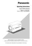
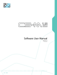
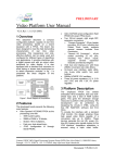
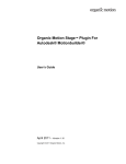
Design Tools for Rapid Prototyping of Embedded
Controllers
Manuel Almeida, Bruno Pimentel, Valery Sklyarov, Iouliia Skliarova
Department of Electronics, Telecommunications and Informatics, IEETA
University of Aveiro, 3810-193 Aveiro, Portugal
[email protected], [email protected], [email protected], [email protected]
Abstract
Electronic devices used in the scope of robotics and embedded systems have to be adapted to numerous external
events and many of them might be unknown in advance. This application-specific particularity requires
environment-specific adaptation and frequent changes in the predefined behaviour. In general, all feasible
functionality cannot be incorporated in the device during the design phase, i.e. some eventual modifications are
postponed until physical tests in real working conditions. Even after executing physical tests, some unexpected
events (requiring the appropriate device reaction) might appear. Thus, either sophisticated adaptable electronics
has to be implemented or the device has to be able to communicate with another more intelligent host computer,
which would assist to cope with emerging problems. The paper suggests tools that provide support for dealing
with the considered situations. This is achieved through the following: 1) FPGA-based prototyping core board
(reconfigurable platform) establishing both wired and wireless interactions with host computers; 2) Design
templates and libraries for interacting with standard peripheral equipment and widely used components for
different types of control and computations; 3) Software providing support for interactions with the core board;
4) Intellectual property cores for solving a number of optimization problems common to many engineering
applications.
Keywords: FPGA, prototyping, VHDL templates, design library, reconfigurable systems, remote
configuration
1
•
Since FPGA-based systems might be configured
not only statically but although dynamically then
we can construct virtual systems than might
require more resources than resources available
on FPGA chip. Indeed since dynamic
reconfiguration makes it possible to change
functionality of FPGA during run time, we can
partition a complex system into subsystems
functioning sequentially. As soon as one
subsystem has completed the required
functionality, hardware for the subsequent
subsystem
can
be
provided
through
reconfiguration of the same FPGA;
•
The design lead time for FPGA-based system is
much shorter than for ASICs.
Introduction
Modern Field Programmable Gate Arrays (FPGA) are
composed of programmable logic cells, memories,
arithmetical devices, processors, circuits for advanced
synchronization, etc. The majority of the FPGA
components can change their functionality and
interconnections between the components can
arbitrarily be established both through reprogramming
the relevant chip. This opportunity opens practically
unlimited capabilities of FPGA-based systems for
rapid prototyping, which is a demanded technique for
robots and embedded systems.
Let us summarize the most important basic features of
FPGA-based systems:
•
The implemented circuit can be optimized for a
particular application. This permits to reduce the
number of the necessary clock cycles, to execute
(as many as required) operations in parallel, to
chose the most appropriate device architectures,
etc.;
•
Although a clock frequency of FPGAs is much
slower than for ASICs we can benefit from
optimized architectures and practically unlimited
prototyping facilities, which, in particular, allow
different
competitive
and
alternative
implementations and algorithms to be examined
and compared;
Numerous advantages of FPGAs make reconfigurable
platforms an ideal target for modern embedded
systems that combine high computation demands with
dynamic task sets [4]. A number of FPGA-based
prototyping boards have been manufactured and they
enable the designers to verify alternative and
competitive engineering solutions. Using such boards
simplifies significantly the design of new FPGAbased applications and allows the development lead
time to be shortened. Very often we can take full
advantage range of hardware capabilities of
prototyping boards if the relevant design tools are
provided, namely design templates, design libraries
and intellectual property (IP) cores. The paper
discusses one of the approaches in this scope
Note that a large number of available FPGA-based
prototyping systems makes it difficult to find the best
choice for a particular application and, as a rule, it is
necessary to find a compromise between the required
hardware/software resources and the price. Taking
into account the fact that the majority of prototyping
boards/systems include many typical components
(such as memories, liquid crystal displays - LCDs,
standard interfaces, etc.) it is very difficult to find a
board optimally targeted to the particular application,
i.e. such a board that contains only those elements that
are required for a particular design problem and no
other components, which just increase the cost and
occupy the space. The paper suggests a technique
permitting to overcome this problem, which has been
achieved through the design of an extendable set of
hardware/software tools easily retargeted to different
engineering application areas. Any particular problem
can be solved using just the selected subset from the
considered set, which includes only the needed
hardware/software components and excludes all the
other available components. In case if the desired
components are not available they can be constructed
easily.
•
Simulation in computer using general purpose
and application-specific software;
•
Hardware/software co-simulation [5] in such a
way that the developed FPGA-based controller
interacts with virtual sensors and actuators
displayed on PC monitor screen (see figure 1)
and their activity (much like the activity of
analogous sensors and actuators in physical
systems) is supported by the relevant software
models.
•
Hardware libraries that enable the designers to
communicate with typical peripheral devices (see
the right-hand part of figure 1). This is very
helpful for debugging purposes.
Simulation of an execution
unit in virtual mode on PC
monitor screen
interface with PC
Extension hardware for
interactions with sensors
and actuators
In general, the suggested tools possess the following
distinctive features:
•
Socket
The core FPGA can be configured using wired
(USB) and in future wireless (Bluetooth)
interfaces, which makes the prototyping system
ideal for remote applications, such as that are
needed for robotics and embedded systems;
•
The developed software/hardware components
provide support for both dynamic onboard
reconfiguration
and
remote
wireless
reconfiguration and/or interaction;
•
The design process is supported by various
supplied tools, such as hardware description
language (VHDL in particular) templates, design
libraries and IP cores. Some of them are targeted
to the remote control and the reconfigurability.
The remainder of this paper is organized in six
sections. Section 2 describes FPGA-based embedded
controllers. Section 3 considers FPGA-based
prototyping systems. Section 4 shows how remote
interactions with the board can be established.
Sections 5, 6 present the developed software tools,
hardware and language templates, IP cores and design
libraries. The conclusion is in section 7.
2
USB module
FPGA-based embedded
controllers
The main objective of the proposed tools is illustrated
in figures 1 and 2. We would like to divide the design
process of an embedded controller into two stages.
The first stage is verification and debugging of the
developed application at different levels of
abstraction, namely:
Figure 1: Using wired interfaces for testing and
debugging purposes.
After the controller has been tested it can be
connected to the proper physical system (see figure
2). At this stage we can use the same prototyping
board replacing USB interface block with Bluetooth
wireless interface block, which can be inserted in the
same socket. After that we still have support for
debugging through remote interactions. This permits
many useful functions to be implemented, such as:
•
Reading and verifying
intermediate states;
•
Remote reconfiguration;
•
Intellectual assistance from the host computer,
which evidently possesses more powerful
hardware/software resources;
•
Hardware support for virtual capabilities allowing
the controller to be constructed on an FPGA that
does not have sufficient hardware resources to
accommodate all the required functionality, etc.
the
controller’s
In order to implement the considered technique many
different software/hardware components have been
developed, namely:
•
Drivers for USB/Bluetooth interfaces;
•
Software supporting functions, illustrated in
Figures 1 and 2;
•
Design templates permitting dynamically
reconfigurable circuits to be constructed;
•
Design libraries to support interfaces with typical
peripheral devices (see figure 1);
•
IP cores for solving numerous optimization
problems formulated over binary and ternary
matrices;
•
Hardware/software tools for data compression
and decompression.
Embedded
controller
Wireless
communication
first section contains a bitstream that has to be preloaded to FPGA in order to allow the following set of
operations: 1) transferring an application-specific
bitstream to the second section; 2) erasing flash
memory sectors; 3) transferring data from a host
device to the third section of the flash memory and
vice versa. This technique has already been used in
Trenz prototyping boards [7]. The second logical
section is used to store an application-specific
bitstream for subsequent quick loading into the FPGA
(using the “project” pushbutton). The third memory
section enables the designer to store additional
bitstreams for configuring the FPGA or any arbitrary
data such as bitmaps for a VGA monitor.
Socket
Bluetooth module
Interface
socket
Wireless
communication
Embedded
controller
Socket
Bluetooth module
Socket
Figure 2: Using wireless interfaces.
3
FPGA-based prototyping system
The basic architecture of the developed prototyping
system (see figure 3) is organized in such a way that it
permits to provide the following features:
•
Powering and programming the board from PC
through USB port. If necessary an external power
source can also be used;
•
Keeping bitstreams for the FPGA in a flash
memory, which permits to use the board as an
autonomous device without any connection to PC
and only external powering has to be provided;
•
Keeping more than one bitstream in the flash
memory for dynamic reconfiguration of FPGA.
The capacity of the selected flash memory permits
to store up to 8 bitstreams. This is very practical
not only for run-time reconfiguration but also for
verification of different types of alternative and
competitive implementations;
•
User-friendly software interface for programming
the board and data exchange with PC;
•
Data exchange with any other device supporting
standard USB port;
•
Extension connectors for interacting with
application-specific externally connected devices.
In general, this architecture presents further
improvements over the previously designed
prototyping system [6]. The flash memory is divided
into three logical sections, as shown in figure 4. The
Figure 3: Basic architecture of the prototyping
system.
First logical section
Bitstream for
configuration
Second logical section
User bitstream
Third logical section
User data /
alternative
bitstreams
Figure 4: Dividing the flash memory into logical
sections.
To download the bitstream to the first logical section
of the flash memory a JTAG connector [2] is
employed. JTAG mode has to be used just once during
the board manufacturing. After that, the developed
software permits to store new bitstreams if required.
The CPLD (see figure 3) is needed for controlling the
flash memory and pushbuttons assembled on the board
because during configuration the FPGA cannot
execute these functions. The CPLD generates also an
initial reset signal for FPGA circuits as soon as a new
configuration is completed.
The board contains a powerful FPGA of Xilinx
Spartan-3 family, namely XC3S400 [2], based on
90nm technology, with 400000 system gates, 56Kb of
distributed RAM, 288Kb of block RAM, 16
multipliers and 264 inputs/outputs. For shortening the
reconfiguration time, a parallel mode has been chosen.
Extension connectors permit to attach any applicationspecific external hardware, which enables the designer
to optimize resources, to improve performance and to
extend the functionality (see figure 1). Generalpurpose extensions make possible to construct
embedded systems interacting with the desired
standard peripheral devices.
The USB controller (version 2.0) provides data
exchange with PC for downloading FPGA bitstreams
and interactions between the FPGA and external
hardware.
4
Remote functions
By replacing the USB controller with a Bluetooth
module, the FPGA can be configured remotely.
The bitstream stored in the first section of the flash
memory, which is used for configuration purposes,
automatically identifies the module attached to the
socket and changes its behavior accordingly. In
contrast to parallel mode provided for USB interface,
the Bluetooth module functions in a serial mode, (8
bit data, 115200 baud-rate, no parity bit and one stop
bit).
The developed software tools [6] (see section 5 for
details) have been modified in order to provide
support for the new functionality based on serial
interface for the constructed Bluetooth module. From
the end-user point of view this functionality is exactly
the same as for the USB module and the difference is
just in an opportunity of a remote interaction with the
board instead of a wired interaction.
Note that an external power source is required if
Bluetooth module is used. A small battery-based
power source can be supplied to provide the required
portability.
5
Software tools
A software program called PBM (Prototyping Board
Manager) has been developed and it provides a
convenient
user-friendly
interface
(partially
demonstrated in figure 5) and powerful design tools.
The most important function is managing a user
bitstream in the second section for quick loading into
the FPGA by pressing the “project” button. This
technique is the most appropriate to integrate design
workflows for single-bitstream projects.
Functions to transfer data from a file to the third
section of the board’s flash memory and vice versa
are implemented as well, so additional user bitstreams
can easily be stored in the flash memory and retrieved
for future use if required.
PBM also features a terminal window for run-time
data exchange between a user and the prototyping
system, thus constituting an integrated input/output
peripheral, which is ideal for project monitoring and
testing.
VHDL description
ISE
PBM application
bitstream
Prototyping board running
configuration bitstream
Bitstream
uploading tool
FPGA
EDIF file
Data transferring
tool
USB or
Terminal Window
Bluetooth
DK
Handel-C
specification
Application-specific
software program
other
devices
Flash
Prototyping board running
user bitstream
FPGA
Extension
connectors
Flash
Figure 5: An example of interactions between
software and hardware.
A more advanced function allows to send multiple
bitstreams and to store them in the third section of the
flash memory (see figure 4). Such a tool is
appropriate for three different purposes:
1.
Autonomous experiments with different singlebitstream projects without connection to a host
computer. In particular this mode can be used to
compare and validate alternative/competitive
implementations. The third section of the flash
memory is logically subdivided in 6 predefined
sectors for storing bitstreams. Selecting the
desired one is achieved with the aid of a simple
additional switcher attached through extension
connectors, which indicates the proper sector for
the CPLD. The same function can be executed
remotely through wireless interface.
2.
FPGA dynamic reconfiguration, using techniques
such as those described in [8,9]. These techniques
permit to implement circuits that require more
resources than the resources available in the
FPGA through run-time reconfiguration.
3.
Programming FPGAs installed on additional
extension boards. In this case, the core FPGA is
considered to be a controller (manager) for a runtime reconfigurable system, which is composed
of multiple FPGAs.
The software application includes the user manual in
English and in Portuguese languages (also available
online [10]) which gives detailed information on how
to take full advantage of all the available
functionality.
In order to be able to work with PBM, the user must
first press the board’s “configuration” button allowing
to load the bitstream from the first section of the flash
memory into the FPGA. This bitstream configures the
FPGA to implement a finite state machine in
accordance with the protocol (either USB or
Bluetooth) also recognized by PBM. Each function
available for the user generates a sequence of basic
operations to be supported by this protocol, such as:
erase a sector, read from pre-specified range of
addresses, write a sequence of bytes, etc.
Table 1 presents the average time for performing
some of the tasks listed above using the USB
protocol. Note that a) each sector has 64 KB, b)
writing operations time includes the time for erasing
the corresponding sectors and c) writing a bitstream
involves 4 sectors. Table 1 demonstrates that the
developed PBM is faster than the tools [7].
Table 1: Average time for executing PBM functions.
Function
Erase a sector
Read a sector
Write a sector
Write bitstream
Average time (s)
0,7
0,4
1,5
5,5
In order to allow PBM to be used with future
prototyping hardware, some guidelines for designing
have been established, which guarantee future
compatibility. The set of guidelines is organized in 3
scopes: board architecture, configuration bitstream
and board specifications file. The first relates to the
board construction and hardware properties; the
second, to the protocol employed to communicate
with the application; the last one to the file containing
information about the board allowing PBM to manage
bitstreams and data transfers correctly.
Analogously, the compatibility between the
considered prototyping board and a future version of
PBM with a modified interaction protocol has also
been taken into account. For such purposes the
developed software includes a tool for storing another
configuration bitstream (implementing the new
protocol) in the first section of the board’s flash
memory. After this operation, pressing the
“configuration” pushbutton will load the new
bitstream into the FPGA and the latest version of
PBM can then be used.
From figure 5 we can see that the developed software
can collaborate with commercial CAD systems in
such a way that PBM supplies all kinds of low-level
functionality, device drivers, interface and debugging
facilities and CAD systems make it possible FPGA
based circuits to be designed.
For example, user projects can completely be
managed in Xilinx ISE [2] or in any similar
environment, which finally generates a bitstream that
is ready for downloading to FPGA. System-level
specification tools (such as Celoxica DK design suite
[11]) can also be used. For instance, in figure 5 the
design suite of Celoxica translates a Handel-C project
description to an electronic design interchange format
(EDIF) file, which is further converted in ISE to a
bitstream for the FPGA.
It is also possible to develop application-specific
software which will communicate directly with the
board (see figure 5), i.e. without using PBM. This
possibility is useful to build solutions that require
collaboration between software and hardware
components, such as co-processing systems and
portable devices with computer-based maintenance.
6
Templates, design libraries and IP
cores
Basically, templates, design libraries and IP cores can
be taken from the previously developed tools for other
prototyping boards namely TE-XC2Se [7], RC100,
RC200 [11] and ADM-XPL PCI [12]. Thus, this
section reviews the previous authors’ results and
shows how they can be adapted to the new
prototyping platform.
The tools proposed in [13] include reusable
specifications of hardware components (modules) that
have been developed for two types of CAD
environments; Xilinx ISE [2] and Celoxica DK [11].
The components can be employed to implement both
application-specific blocks for optimization purposes
and a number of standard interfaces that are very
useful for interaction and data exchange with devices
attached to the FPGA, such as LCD and touch panels,
bus controllers, etc. (see figure 1). The designed
modules can be easily integrated into any applicationspecific digital system and used for visualizing the
results, fast data transfer, debugging of internal subcircuits, etc. They were constructed in such a way that
their functionality can be either fixed or modifiable
(both statically and dynamically). The latter capability
was provided with the aid of re-loadable RAM-based
blocks. To illustrate the capabilities of the tools
suggested, four design examples were discussed in
[13] (the relevant projects are available online).
There are three following types of reusable
components that have been developed (based on the
previous results) for the new reconfigurable platform:
1.
Hardware and VHDL templates. A hardware
template is a circuit with predefined connections
between all primarily components. The
functionality of the circuit can be customized
through reconfiguration of the alterable circuit
blocks, which are RAM blocks. An example of
such circuit is given in [14]. VHDL templates are
considered to be skeletal code fragments
(described in hardware description language –
VHDL), which can easily be customized for
particular functionality. They are used much like
language templates supplied with Xilinx ISE [2].
An example of VHDL template for a hierarchical
finite state machine is given in [15].
2.
Design libraries, which are considered to be
fragments of parameterizable VHDL code, which
can be inserted to any project requiring the
respective facilities (for example, requiring USB
or RS232 serial communication). VHDL libraries
of such type have been developed for many
standard interfaces and peripheral devices, such
as RS232, VGA, mouse, keyboard, static RAM,
flash RAM, etc.
Parametrization has been
provided through VHDL generic and generate
statements.
3.
IP cores have been implemented for matrix based
optimization (1) and compression/decompression
(2) algorithms, which are often required for
robotics and embedded applications. The first
group (1) of algorithms permits to solve various
problems over binary and ternary matrices, which
include matrix covering [16], Boolean
satisfiability [17], graph colouring, etc. These
tasks are very important for many engineering
applications [18] (see, for example, [19]). The
second group (2) of algorithms makes possible
the volume of transmitted data between a host
computer and the prototyping board to be
reduced. For such purposes methods described in
[20] have been employed.
For points 1 and 2 above just trivial changes have
been provided and the previously developed projects
have been recompiled in recent CAD environments.
Adaptability of the previously developed tools
indicated in point 3 has been mainly achieved through
modification of interfaces with the host computer.
7
[7]
[8]
[9]
[10]
[11]
[12]
[13]
[14]
Conclusion
The paper suggests tools enabling the designers of
electronic devices to simplify many synthesis and
verification problems. They include: 1) the core
prototyping system (CPS); 2) CPS-oriented software;
3) two types of design templates, design libraries and
IP cores for solving optimization problems over
binary/ternary
matrices
and
for
data
compression/decompression.
8
[6]
References
V.Sklyarov, I.Skliarova, “Teaching Reconfigurable
Systems:
Methods,
Tools,
Tutorials,
and
Projects”, IEEE Transactions on Education, vol. 48,
n.º 2, pp. 290-300 (2005).
[2] Xilinx, Inc., products and services, available at:
http://www.xilinx.com/, visited on 10/7/2006.
[3] L. Benini, G. De Micheli, “Networks on Chip: A New
SoC paradigm”, IEEE Computer, pp 70-78 (Jan.
2002).
[4] C. Steiger, H. Walder, M. Platzner, “Operating
Systems for Reconfigurable Embedded Platforms:
Online Scheduling of Real-Time Tasks”, IEEE Trans.
on Computers, vol. 53, no. 11, pp 1393-1407 (2004).
[5] V. Sklyarov, “Hardware/Software Modeling of FPGAbased
Systems”,
Parallel
Algorithms
and
Applications, ISSN 1063-7192, vol. 17, nº 1, pp 19-39
(2002).
[15]
[16]
[17]
[1]
[18]
[19]
[20]
M. Almeida, V. Sklyarov, I. Skliarova, B. Pimentel,
“Design Tools for Reconfigurable Embedded
Systems”, Proceedings of the 2nd International
Conference on Embedded Software and Systems,
China, pp 254-261 (2005).
Spartan-IIE Development Platform, available at:
http://www.trenz-electronic.de, visited on 10/7/2006.
N. Shirazi, W. Luk, P. Y. K. Cheung, “Run-Time
Management
of
Dynamically
Reconfigurable
Designs”,
8th
International
Workshop
on
Programmable Logic and Applications - FPL'98,
Springer, pp 59-68 (1998).
V. Sklyarov, A.A. da Rocha, A.B. Ferrari, “Synthesis
of Reconfigurable Control Devices Based on ObjectOriented Specifications”, Advanced Techniques for
Embedded Systems Design and Test, Kluwer
Academic Publisher, pp 151-177 (1998).
PBM
user’s
manual,
available
at:
http://www.ieeta.pt/~iouliia, visited on 10/7/2006.
Celoxica
products,
available
at:
http://www.celoxica.com, visited on 10/7/2006.
Alpha Data products, available at: http://www.alphadata.com, visited on 10/7/2006.
V. Sklyarov, I. Skliarova, P. Almeida, M. Almeida,
“Design Tools and Reusable Libraries for FPGABased Digital Circuits”, Proceedings of EUROMICRO
Symposium on Digital Systems Design – DSD’2003,
Turkey, IEEE Computer Society, pp 255-263 (2003).
V. Sklyarov, I. Skliarova, A. Oliveira, A. Ferrari, “A
Dynamically
Reconfigurable
Accelerator
for
Operations over Boolean and Ternary Vectors”,
Proceedings of EUROMICRO Symposium on Digital
Systems Design – DSD’2003. Turkey, IEEE Computer
Society, pp 222-229 (2003).
V. Sklyarov, “FPGA-based implementation of
recursive
algorithms”,
Microprocessors
and
Microsystems, Special Issue on FPGAs: Applications
and Designs, vol. 28/5-6, pp 197-211 (2004).
I. Skliarova, A.B. Ferrari, “The Design and
Implementation of a Reconfigurable Processor for
Problems of Combinatorial Computation”, Journal of
Systems Architecture, Special Issue on Reconfigurable
Systems, vol. 49, nos. 4-6, pp 211-226 (2003)
I. Skliarova, A.B. Ferrari, “A Software/
Reconfigurable Hardware SAT Solver”, IEEE
Transactions on Very Large Scale Integration (VLSI)
Systems, vol. 12, n. 4, pp 408-419 (2004)
I. Skliarova, A.B. Ferrari, “Reconfigurable Hardware
SAT Solvers: A Survey of Systems”, IEEE
Transactions on Computers, vol. 53, issue 11, pp
1449-1461 (2004).
R. Feldman, C. Haubelt, B. Monien, J. Teich, “Fault
Tolerance Analysis of Distributed Reconfigurable
Systems Using SAT-Based Techniques”, Proceeding
of FPL’2003, Portugal, pp 478-487 (2003).
V. Sklyarov, I. Skliarova, B. Pimentel, J. Arrais,
“Hardware/Software Implementation of FPGAtargeted Matrix-Oriented SAT Solvers”, Proceedings
of the 14th International. Conference on FieldProgrammable Logic and Applications – FPL’2004,
Belgium, pp 922-926 (2004).