1
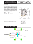
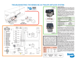
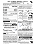
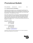
User Manual TRAILteck T03 Contents: Warning Panneau de contrôle Spécifications External requirements The Storage Battery Operation The On/Off (Power On) Switch: #9 The manual or remote-control activation switch: #10 Manual Accessory Switches: #1 to #8 Programming a remote control Fifteen-function remote control Eight-function remote control Checking for air leaks on a semitrailer Electric and Electronic Components Remote control The relay (inside the unit) The Self-diagnostic System The wiring harness outlet The charger/power pack Pneumatic Components Regulators Air valves Available options Warning lights on the front of the unit To verify if the trailer functions are activated To verify the truck’s electrical wiring harnesses Inspection system for the truck Inspection of the truck’s air pressure Finding an air leak on the truck Checking the TRAILteck unit’s tightness Using truck air as a source to feed the TRAILteck unit Circuits analyser Current Management Readings High-voltage alarm Limited warranty Contact us 3 4 5 5 5 5 5 5 5 6 6 6 6 7 7 7 7 8 8 8 8 8 9 10 10 10 12 12 13 13 13 14 14 15 15 16 17 Warning Welding: It is very important to avoid using the TRAILteck unit when welding is being carried out on the trailer. Doing so may create a current loop that will damage the unit. Power failure: In the case of a power failure, all activated functions will be shut down if a battery has not been installed in the unit. Therefore, for security purposes, always have a 12-volt battery in working conditions installed in the unit in order to prevent injuries. 3 Control pannel 19 15 11 4 20 17 16 12 13 14 18 Specifications External requirements The TRAILteck unit was designed to work by battery or by using standard 120 volt AC power. When plugged into an outlet, the integral electronic charger (UL approved and completely automatic) can charge a battery. Compressed air of between 100 and 140 psi is required for the unit to function. The air source can be a compressor or the truck itself. This air must be clean and dry. For your safety, the air intake going into the unit is fitted with a check valve. The Storage Battery When not plugged into an outlet, the TRAILteck unit can work off Group 24, 27, or 31 batteries. Such batteries must be purchased separately. In order to prolong the life of the unit, a deep discharge battery should be used. The recommended type, rated at 12 volts and 85 amp/hours, can supply an average maximum charge of 640 M.C.A. (10 amps for 7.5 hours). TRAILteck’s average autonomy is about six hours between charges. Operation The On/Off (Power On) Switch: #9 Press this switch to turn on the unit. A “Power On” warning light will indicate the unit is working. Once on, pressing the switch a second time will turn the unit and the warning light completely off. A second warning light (Overload) is situated next to the “Power-on” switch. This light turns on when the accessories are drawing more than 40 amps. If this occurs, a breaker will automatically turn off accessories #1 to #4. However, as a safety measure, accessories #5 to #8 (which deal with the air supply to the trailer) will remain operational. An Overload will occur if your trailer has a major electrical problem or if it has an unusually high number of lights. The Overload function was designed to protect the user should the battery discharge too abruptly. The manual or remote-control activation switch: #10 This switch is used to toggle between manual and remote-control modes. When this switch is activated, the unit works automatically in remote control mode by default. A green warning light will indicate that the unit is ON. By pressing the switch a second time, the unit begins to function in manual mode and another warning light will turn on to confirm this fact. For the safety of your mechanics, it is impossible for the unit to work in manual and remote control modes at the same time. When switching from one mode to the other, functions #1 through #8 will be deactivated automatically. Manual Accessory Switches: #1 to #8 5 There are eight switches on the TRAILteck control panel. These switches control the semitrailer accessories manually. A green warning light will turn on when a corresponding function is activated. Pressing on the corresponding switch another time can deactivate each function. The eight switches are: #1 #2 #3 #4 #5 #6 #7 #8 Parking lights Marker lights Left flasher Right flasher Emergency-air suspension Service-brakes Suspension switch (#5) must be turned on for the brakes to be operational The brake lights can be turned on whether or not the suspension is activated Air lift Suspension switch (#5) must be activated ABS or communication system (PLC4TRUCKS) Programming a remote control A remote control can be programmed very quickly in two easy steps. Fifteen-function remote control 1. Press on the #9 switch on the control panel and hold it for seven seconds. The power switch light will flash. 2. Then press on the lower right-hand button (OPT 5) on the remote control. Eight-function remote control 1. Press on the #9 switch on the control panel and hold it for seven seconds. The power switch light will flash. 2. Then press on the upper left-hand button (#1) on the remote control. The unit is now programmed. Test the remote control. If you have turned on the programming mode by mistake, simply press on button #9 or #10 to cancel the error. Checking for air leaks on a semitrailer The TRAILteck unit can be used to detect air leaks on a trailer and to determine the source and seriousness of these leaks. Carry out the following steps: 1. Connect a compressed air supply to the TRAILteck unit 2. Connect the unit to the semitrailer Emergency Service Power cord 6 3. 4. 5. 6. 7. Turn on the Emergency function (#5) Allow the pressure to stabilize Turn on the Service function (#6) Allow the pressure to stabilize once more Disconnect the compressed air source from the TRAILteck unit The air intake is fitted with a check valve and each of the two circular pressure gauges (#16 and #17) on the control panel function independently. One valve (#17) is for Service and the other (#16) is for Emergency. This allows you to determine if there is an air leak on the semitrailer, which circuit is leaking and, if necessary, how serious the leak is. Electric and Electronic Components Remote control The remote control allows you to turn on each accessory independently from a safe distance. The 15-function remote operates at a frequency of 315 MHz over a theoretical distance of 200 ft. The 8-function remote operates at a frequency of 315 MHz over a theoretical distance of 100 ft. Each remote control is encrypted so that it can control only the unit for which it has been programmed. The relay (inside the unit) Automobile relays feed each automatic breaker fitted to the electrical connector. These are standard relays that can be found in virtually every motorized vehicle. They are extremely reliable and easy to change. For ease of maintenance, each relay is identified by number that corresponds to a number on the control panel. The Self-diagnostic System Red warning lights (#19): These lights indicate the state of the breakers on the unit. When a semitrailer has a short circuit and the breaker on a particular electrical circuit trips, this warning light will show you: That there is a short circuit on the trailer On which outlet the problem is occurring (because there are two) Which breaker (electrical circuit) is affected This will be an enormous help to the user. The problem will be found quickly because the breakers activate automatically once a short circuit is repaired. Yellow warning lights (#20): These warning lights were designed using basic electromechanical concepts to allow the user to carry out certain minor repairs to the TRAILteck unit. Each electrical circuit is activated by internal relays. These lights show which circuit is defective. This allows you to change the defective relay with the spare relay that can be found inside the unit. If 7 changing the relay does not solve the problem, this means that the relay was not defective and that there is a problem with the circuit inside the unit. The wiring harness outlet A 15 amp automatic breaker protects each power line. The TRAILteck is fitted with both STANDARD J560 and ABS ISO connectors required by all 3 and 4-axle trailers equipped with ABS. This makes the unit compatible with both types of wiring harness. The charger/power pack The integrated charger/power pack is completely automatic and meets and exceeds UL specifications. It has two distinct functions: As a power supply when there is no battery in the unit. This allows the unit to be plugged in and working on 120 V at all times. As a charger when there is a battery in the unit. The charger turns off automatically once the battery is completely charged. Pneumatic Components Regulators The two integrated regulators are both adjustable and independent: Left (#15): Right (#18) Red gladhand-Emergency Blue gladhand-Service Air valves Two air valves are fitted to the unit, one for each pneumatic circuit. Air is supplied to the unit by color-coded tubing: 8 Red for emergency Blue for service Available options Warning lights on the front of the unit Inspection system for the truck Circuits analyser 9 Warning lights on the front of the unit The front warning lights are color-coded: Green for Marker and Parking lights Orange for the Flashers (left and right) Red for the electrical and air systems (suspension and brakes) Blue for the air lift axle and the ABS system They have two main functions: To verify if the trailer functions are activated To verify the truck’s electrical wiring harnesses To verify if the trailer functions are activated The unit has separate warning lights for each accessory function. Once a function is activated, the corresponding warning light will turn on. The technician can therefore see at a distance which TRAILteck accessory is activated. A lit warning light can also indicate that the unit has received the remote control signal. To verify the truck’s electrical wiring harnesses Short circuits: 10 The warning lights allow the inspection of the truck’s electrical wiring harness. The technician simply has to connect the wiring harness of the vehicle to either of the TRAILteck connectors and then alternately turn on each of the truck’s electrical accessories. For example, when you turn on the Parking lights, the corresponding warning light will turn on the same time. If there is a short circuit between the Parking lights and the Flashers, the warning light for the flashers will light up when you turn on the Parking lights. Bad connections: Many electrical wiring harness problems are not due to short circuits between wires but, rather, to bad contact(s) inside the connector. Therefore, once it has been determined that there is no short circuit: 1. Turn on all electrical accessories 2. Shake the electrical wiring harness Faulty or intermittent connections will cause the unit’s front lights to flash when the wiring harness is shaken. 11 Inspection system for the truck Two gladhands are installed on the back of the unit. The bleue gladhand is connected to the Service circuit (brake) The red gladhand is connected to the Emergency circuit (suspension) Verification of the truck’s air pressure This function allows you to determine if the air pressure supplied by the truck is working correctly. 1. Connect the gladhands from the truck to the corresponding colored gladhand on the rear of the TRAILteck unit 12 2. Compare the air pressure indicated on the truck gauges with that on the unit’s control panel. This allows you to check the air pressure supplied by the truck for the Emergency and the Service of the trailer. Finding an air leak on the truck This function allows you to determine if there is a leak on the pneumatic system supplying the trailer. Because the gauges are independent (Emergency and Service), it is possible to determine which pneumatic system is leaking. 1. Connect the truck’s air gladhand to the corresponding colored gladhand on the unit. 2. Press on Emergency button and lower the hand brake lever so that air is sent to the TRAILteck unit. 3. Allow the unit’s gauges to stabilize and then check the truck’s gauges to see if there has been any fall in pressure. Checking the TRAILteck unit’s tightness This inspection is carried out to ensure that the TRAILteck unit is leak proof. You will then be able to carry out leak tests on pneumatic circuits of the truck and trailer in total confidence. 1. 2. 3. 4. Connect the TRAILteck gladgrips to the gladhands at the back of the unit. Turn on the Emergency and Service pneumatic functions Let the air gauges stabilize, then disconnect the air from the unit Check the gauges on the unit to see if the pressure inside the unit drops. If it does, there is a leak in the unit. Using truck air as a source to feed the TRAILteck unit The truck can be used a source of compressed air to feed the TRAILteck unit. This is done by connecting the truck air gladhands to the TRAILteck unit and then connecting the unit to the trailer. By positioning the TRAILteck between truck and the trailer, you'll be able to diagnose problems on one or other of the connections. 13 Circuits analyser The circuit analyser on the TRAILteck unit has several functions. The "MODE" button activates each of the system's functions one at a time. This is very useful for detecting and repairing short circuits. This digital multimeter will become an indispensable tool in any mechanic's arsenal. Circuits analyser functions: Current Management When the unit is working off a battery (instead of 120-volt source) and the voltage drops below 11.5 volts for more than 60 seconds, an audible and visual alarm will go off but only the electrical accessories (lights) will be turned off. The pneumatic accessories will continue working until the voltage drops below 11 volts. In the latter case, another visual 14 and audible alarm will go off and the unit will then shut down completely. To turn the unit back on, simply press the "RESET" button or plug the unit into any electrical power outlet. The digital multimeter can indicate maximum current of 0 - 100 amp. (precise to 0.01amp.) and can measure voltage from 8 -17 volts (precise to 0.01 volt). Readings Charged current o This function displays the current charging the battery Discharged current o This function displays the drain current on the semi-trailer. It can also determine if there are any corroded or defective connections. The system works as follows: 1. 2. 3. 4. Activate all the electrical functions on semi-trailer Leave the current displayed for about one minute Check to see if the drain current is stable, rising or falling. If the current increases gradually, this indicates an increase of resistance in the electrical circuit. This resistance is caused either by a faulty connection, by corrosion, or by a defective light 5. Deactivate the unit’s electrical function 6. Then reactivate each electrical function one at a time in order to determine which circuit is having the problem High-voltage alarm In the case of a fault in the charging system, an audible and visual alarm will go off to warn the technician to plug the unit into a 120-volt source so that the built-in battery is not damaged. 15 Limited warranty This product is covered by the manufacturer’s warranty for eighteen (18) months from the date of purchase by the original purchaser against any defect in materials or workmanship. Application: The first six months: parts and labor including shipping costs For the following twelve months: parts and labor but shipping or travel costs are not covered The warranty does not apply to batteries The external components of the unit are warranted for a period of 30 days from the date of purchase The external components include: o o o o o Electrical cables Pneumatic hoses Gladhands, gladgrips Electrical connectors Tires Parts deemed defective during this period will be replaced or repaired at the manufacturer’s discretion. The manufacturer reserves the right to replace the complete unit in lieu of parts. This warranty does not cover failures due to damage caused by accident or during transport, by inappropriate manipulation or operation, by abuse, by inappropriate use, or by repairs carried out by unauthorized persons. This limited warranty supersedes any other warranty, express or implied, including warranties of merchantability or fitness for a particular purpose, nor will the manufacturer be held responsible for fortuitous damages for any reason whatever. 16 To contact us: Redtech Inc. 1444 JB Michaud Drummondville QC Canada J2C 7V3 T: (819) 472-3441 (877) 773-3832 (toll free) F: (819) 475-6355 W: www.redtech.ca @: [email protected] 17