1
3.5 Setting Ethernet Communication Conditions
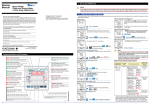
This section explains how to set Ethernet communication conditions by taking as an example the case
when the IP address is changed from the initial value to “192.168.1.2”.
Operation
Measured Value screen
IP Address-4 Setting screen
The screen changes to the one
for setting the parameter
Parameter IP-1 IP-2 IP-3 IP-4
IP address 192.168. 1. 2
1
Using
or
, change the
setpoint.
IP Address-4 Setting screen
VT Ratio screen
The parameter
appears.
(VT ratio)
Using
Ethernet Communication
Menu screen
6
Hold down
for at
least 3 seconds.
To move to the digit to be
changed, use the following
keys:
To the left
To the right
or
, show
2
7
.
Press
twice to
confirm the setpoint.
IP Address-4 Setting screen
Pressing
once causes all
digits of the setpoint to start
blinking. Pressing
once
again confirms the setpoint and
returns to the IP Address-4
screen.
3
To re-set the parameter:
Press any key other than
Press
once.
IP Address-1 screen
while all digits of the setpoint
are blinking.
The PR300 returns to the initial setting
screen.
IP Address-4 screen
To enable the parameter
setting, execute step 8 on the
next page.
The parameter
(IP address-1) appears.
4
Press
times.
three
IP address setting completed.
IP Address-4 screen
The parameter
(IP address-4) appears.
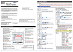
The parameter options change
as shown below.
5
3-8
Press
once.
Each press of
cycles through the parameter
options, as shown below.
Refer to “Parameter Setting Types and Ranges” on the next
page to set other parameters in the same manner.
Subnet mask-1
Subnet mask-2
Subnet mask-3
Subnet mask-4
Default gateway-4
Default gateway-3
Default gateway-2
Default gateway-1
Port number
Ethernet setting switch
IM 77C01E01-01E