1
Startup
Manual
1. Set up the PR300 First
Model PR300
Power and Energy Meter
<Initial Setup Operations>
NOTE
If you change the phase and wire system and the voltage range, all parameters other than those related to RS-485 and Ethernet communications are
initialized (to factory-set values). Change the phase and wire system and the voltage range before setting parameters such as the VT and CT ratios.
1.1
Setting the Phase and Wire System
This section explains how to set the phase and wire system by taking as an example the case when a three-phase four-wire system is changed to a threephase three-wire system.
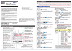
Phase and Wire System Setting screen
Startup screen
Pressing
once causes all digits of the setpoint to
start blinking. Pressing
once again confirms the
setpoint and returns to the Phase and Wire System
screen.
Thank you for purchasing the PR300.
This manual describes the setting procedures of phase and wire system,
voltage range, VT ratio, and CT ratio of the PR300. The electronic manuals
are also provided on the accompanying CD in addition to this manual.
Read them along with this manual. To ensure correct use, be sure to read
the PR300 Power and Energy Meter User's Manual (IM 77C01E01-01E)
thoroughly before beginning operation.
1
Printed manuals (Electronic manuals [PDF files] are also provided on the
accompanying CD.)
The phase and wire system thus set is shown as the
current value.
Turn on the PR300.
Measured Value screen
The PR300 shows the station number for about 5
seconds, then the Measured Value screen * appears.
Model PR300 Power and Energy Meter Startup Manual <Installation> :
IM 77C01E01-02E
Phase and Wire System screen
When proceeding to set the voltage range, start from
Step 6 in Section 1.2, “Setting the Voltage Range,”
with this screen (figure on the left) shown as is.
Model PR300 Power and Energy Meter Startup Manual <Initial Setup Operations>:
Current value
IM 77C01E01-03E (This manual)
2
Electronic manuals (PDF files)
Model PR300 Power and Energy Meter User’s Manual:
Hold down
9
for at least 3 seconds.
The parameter
Model PR300 Power and Energy Meter Communication Interface User's Manual:
for at least 3 seconds.
Measured Value screen
VT Ratio screen
IM 77C01E01-01E
Hold down
The PR300 shows the Startup screen for about 5 seconds,
then the Measured Value screen appears.
(VT ratio) appears.
IM 77C01E01-10E
Please keep this manual for future reference.
3
IM 77C01E01-03E
1st Edition: Feb. 2006 (KP)
Simultaneously hold down
,
and
Setting completed.
for at least 3 seconds.
Specification Change Confirmation screen
The Specification Change Confirmation screen appears.
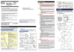
Component Names and Functions
Demand Alarm lamp (Red)
Phase and Wire System lamps (Green)
Comes on if the demand value exceeds the demand alarm point at
any point in time other than the demand alarm mask time.
The phase and wire system option set in the
PR300 turns on.
Pulse Output lamp (Green)
Comes on when the output is turned on in the pulse output
mode and goes out when the output is turned off.
Communication lamp (Green)
Blinks while RS-485 or Ethernet
communication is in progress.
Power lamp (Green)
Comes on and remains lit when the PR300
is turned on and operating normally. Blinks
(4 times/second) if a communication error
occurs, and continues to blink until the
PR300 returns to normal.
Phase Indication lamps (Red)
Come on to tell for which phase the voltage
or current value is being measured.
MAX and MIN lamps (Red)
Come on when the maximum or minimum
measured value is displayed.
Operation keys
In the measured value display mode, this key is used, for example, to
show the maximum/minimum value. Also used to set parameters on the
Parameter screen.
1
, show
on
Specification Change Confirmation screen
Input Range lamps (Green)
Measured Value display (Red)
Shows a measured value of power, energy, etc.
Also shows a parameter symbol and its setpoint
at the time of parameter setting.
Show the unit symbol of a measured value for
each measurement item. These unit symbols are
shown in combination depending on the type of
measured value.
DEMAND lamp (Red)
Range of Phase and Wire System Options
Setting
Type
Setting Range (Details)
Selection Model and Suffix Codes
5
Press
once.
Phase and Wire System screen
The Phase and Wire System screen appears.
Parameter symbol for
phase and wire system
Unit lamps (Red)
•If single-phase three wire system is selected, the voltage
range is fixed at 300V (between P0 and P1, P0 and P2). The
voltage range cannot be selected.
•Three-phase four-wire system (2.5 element) can be used only
when the voltage is in a state of equilibrium. In addition, the
phase and wire system cannot be changed.
Parameter Symbol
Parameter Name
The voltage range option set in the PR300 and
the current range (rated input) option specified
at the time of ordering turn on.
Current value
6
Single-phase
two-wire system
Single-phase
three-wire system
Three-phase
three-wire system
once.
Setpoint
7
Phase and
wire system
Model and Suffix Codes
Press
Phase and Wire System Setting screen
The Phase and Wire System Setting screen appears.
Comes on when the measured value of demand
power or demand current is displayed.
(Only supported for a PR300 with the demand
measuring function.)
In the measured value display mode, this
key is used, for example, to switch the
display pattern. Also used to set parameters
on the Parameter screen.
In the measured value display mode, this key is used, for
example, to move from one digit to another in an energy
reading. Also used to set parameters on the Parameter screen.
4
Using
or
the lower display.
Note
Switch the phase and wire system using
or
.
Single-phase
two-wire system
Single-phase
three-wire system
Three-phase
three-wire system
Three-phase
four-wire system
Model and Suffix Codes
Phase and Wire System Setting screen
Use to start or stop demand measurement. The lamp
(green) in the key lights in the demand measurement.
Three-phase four-wire
system (2.5 element)
In the measured value display mode, this key is used, for example,
to switch the phase of voltage/current. Also used to set parameters
on the Parameter screen.
8
Press
twice to confirm the setpoint.
Initial Value
(Factory-set
Value)
Three-phase
three-wire
system
Three-phase
four-wire
system
Three-phase
four-wire system
(2.5 element)
* The initial value of the Measured Value screen (display pattern) is Upper
display: Current (phase switch indication), Middle display: Voltage (phase
switch indication), and Lower display: Active power. For the display
pattern setting procedures, refer to the PR300 Power and Energy Meter
User's Manual (IM 77C01E01-01E) provided on the accompanying CD.
1.2
2. Setting the VT and CT Ratios
Setting the Voltage Range
This section explains how to set the voltage range by taking as an example the case when the voltage range is changed from 300 V to 600 V.
Voltage Range Setting screen
Startup screen
Pressing
once causes all digits of the setpoint
to start blinking. Pressing
once again confirms
the setpoint and returns to the Voltage Range
screen.
The voltage range thus set is shown as the current
value.
Turn on the PR300.
1
Measured Value screen
The PR300 shows the station number for about 5
seconds, then the Measured Value screen * appears.
2
Hold down
When proceeding to set the phase and wire system,
press
or
to show the Phase and Wire
System screen, with this screen (figure on the left)
shown as is. After showing the Phase and Wire
System screen, start from step 6 in Section 1.1,
“Setting the Phase and Wire System.”
The parameter
10
(VT ratio) appears.
Hold down
Setting the VT Ratio
This section explains how to set the VT ratio by taking as an example the
case when the VT ratio is changed from the initial value (1) to 4.
Prior to proceeding to the following steps, ensure that the PR300 is turned
on, and the Measured Value screen is displayed.
3
and
Using
or
the lower display.
, show
The parameter
1
The parameter
NOTE
3
2
Press
once.
VT Ratio Setting screen
The screen changes to the one for setting the
parameter
and the alterable digit blinks.
Range of Voltage Range Options
5
Press
once.
Setting
Type
Selection
Phase and Wire System screen
The Phase and Wire System screen appears.
Setting Range (Details)
150V
Initial Value
(Factory-set
Value)
3
6
, show the Voltage
4
Voltage Range screen
The Voltage Range screen appears.
Voltage range
Parameter symbol for voltage range
Current value
7
Press
* The initial value of the Measured Value screen (display pattern) is Upper
display: Current (phase switch indication), Middle display: Voltage (phase
switch indication), and Lower display: Active power. For the display
pattern setting procedures, refer to the PR300 Power and Energy Meter
User's Manual (IM 77C01E01-01E) provided on the accompanying CD.
or
, change the setpoint.
Press
To move the decimal point, use the following keys:
To the left
To the right
Press
5
Using
4
Press
VT Ratio Setting screen
Pressing
once causes all digits of the setpoint to
start blinking. Pressing
once again confirms the
setpoint and returns to the VT Ratio screen.
To re-set the parameter:
Press any key other than
6
Press
, change the voltage
Voltage Range Setting screen
2
Press
twice to confirm the setpoint.
CT Ratio Setting screen
Pressing
once causes all digits of the setpoint to
start blinking. Pressing
once again confirms the
setpoint and returns to the CT Ratio screen.
To re-set the parameter:
.
If you do not operate any key for more than 5
minutes on the Parameter screen, the PR300
automatically returns to the Measured Value screen.
Press any key other than
while all digits of the setpoint are
blinking. The PR300 returns to the initial setting screen.
CT Ratio screen
To return to the Measured Value screen, hold down
Setting completed.
9
, change the setpoint.
To move to the digit to be changed, use the following
keys:
To the left
To the right
twice to confirm the setpoint.
To return to the Measured Value screen, hold down
Setpoint
8
or
VT Ratio screen
once.
or
once to fix the position of the decimal point.
CT Ratio Setting screen
while all digits of the setpoint are blinking.
The PR300 returns to the initial setting screen.
Voltage Range Setting screen
The Voltage Range Setting screen appears.
Using
range.
once.
CT Ratio Setting screen
The alterable digit blinks.
To move to the digit to be changed, use the following
keys:
To the left
To the right
300V
600V
Using
(CT ratio) appears.
VT Ratio Setting screen
300V
Using
or
Range screen.
once.
CT Ratio Setting screen
The screen changes to the one for setting the parameter
. The lower display shows the current value and the
decimal point blinks.
Setpoint
Parameter Symbol
Parameter Name
(VT ratio) appears.
Current value
(VT ratio) appears.
Current value
•The voltage range of single-phase three-wire system is fixed at
300V (between P0 and P1, P0 and P2). The voltage range
cannot be selected.
•For the voltage range of three-phase four-wire system, set the
voltage between P0 and P1, P0 and P2, P0 and P3.
Press
The parameter
for at least 3 seconds.
Setting completed.
Specification Change Confirmation screen
for at least 3 seconds.
CT Ratio screen
Hold down
VT Ratio screen
on
Hold down
VT Ratio screen
2
,
for at least 3 seconds.
Specification Change Confirmation screen
The Specification Change Confirmation screen
appears.
4
1
for at least 3 seconds.
Measured Value screen
The PR300 shows the Startup screen for about 5
seconds, then the Measured Value screen appears.
Simultaneously hold down
Setting the CT Ratio
This section explains how to set the CT ratio by taking as an example the
case when the CT ratio is changed from the initial value (1.00) to 10.00.
Prior to proceeding to the following steps, ensure that the PR300 is turned
on, and the Measured Value screen is displayed.
Measured Value screen
Measured Value screen
Current value
VT Ratio screen
Set the VT and CT ratios so that the value of “secondary rated
power ⴛ VT ratio ⴛ CT ratio” is smaller than 10 GW. If this value
exceeds 10 GW, the updated VT or CT ratio will not be
incorporated but revert to the current value before change.
2.1
Voltage Range screen
for at least 3 seconds.
NOTE
2.2
.
If you do not operate any key for more than 5
minutes on the Parameter screen, the PR300
automatically returns to the Measured Value screen.
When proceeding to set the CT ratio, press
once
and start from step 3 in Section 2.2, “Setting the CT Ratio.”
Parameter Setting Types and Ranges
twice to confirm the setpoint.
Initial Value
Parameter Symbol
Setting Type Setting Range (Details) (Factory-set
Parameter Name
Value)
Integral
numeric
1
1 to 6000
VT ratio
value
Setting completed.
Parameter Setting Types and Ranges
Parameter Symbol
Parameter Name
Setting
Type
CT ratio
Floating-point
numeric
value
Initial Value
Setting Range (Details) (Factory-set
Value)
0.05 to 32000
IM 77C01E01-03E
1.00
1st Edition Feb. 13, 2006-00