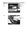
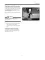
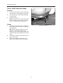
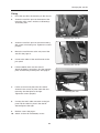
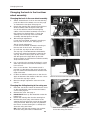
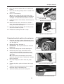
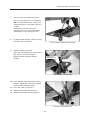
1
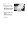
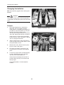
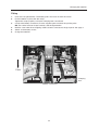
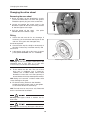
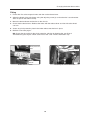
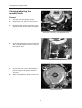
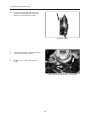
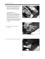
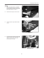
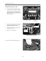
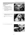
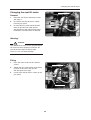
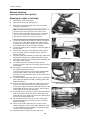
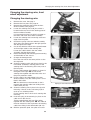
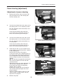
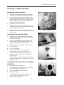
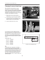
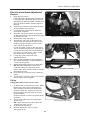
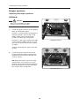
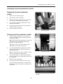
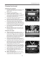
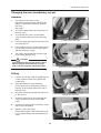
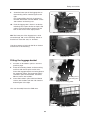
SERVICE MANUAL
Trax
US
How to contact Permobil
Permobil Inc. USA
6961 Eastgate Blvd.
Lebanon, TN 37090
USA
Phone: 800-736-0925
Fax:
800-231-3256
Email: [email protected]
Head Office of the Permobil group
Permobil AB
Box 120
861 23 Timrå
Sverige
Tel: 060-59 59 00
Fax: 060-57 52 50
E-post: [email protected]
Produced and published by Permobil AB, Sweden
Edition no.3, 2010-02
Order no.: 201096-US-0
Contents
Contents
Introduction .........................................................................................................................5
Technical support .............................................................................................................5
Spare parts.......................................................................................................................5
Warranties ........................................................................................................................5
Maintenance.....................................................................................................................5
Rating plates........................................................................................................................6
Raising the seat lift .............................................................................................................7
Covers ..................................................................................................................................8
Changing the batteries .......................................................................................................10
Removal ...........................................................................................................................10
Fitting ...............................................................................................................................11
Changing the drive wheel ..................................................................................................12
Changing the brake release wires.....................................................................................14
Changing/adjusting the magnetic brake...........................................................................16
Changing the drive motor ..................................................................................................19
Removal ...........................................................................................................................19
Fitting ...............................................................................................................................21
Changing the carbon-brush in the drive motor ...............................................................23
Removal of the carbon-brush...........................................................................................23
Fitting the carbon-brush ...................................................................................................24
Changing the seat lift motor ..............................................................................................25
Changing the seat lift .........................................................................................................26
Removal ...........................................................................................................................26
Fitting ...............................................................................................................................27
Changing the bush in the front/rear wheel assembly .....................................................28
Steering knuckle spring mounting in the front wheel assembly ...................................30
Manual steering (moving between the right and left sides) ...........................................32
Changing the steering wire (adjustment) - front wheel adjustment (Toe-in) ................33
Power steering (adjustment)..............................................................................................35
Potentiometer, front wheel assembly ...............................................................................36
Changing the lights/indicators ..........................................................................................37
Changing the wheel base (manually)/Electrical wheel base adjustment ......................38
Bumper positions................................................................................................................40
Pinch protection switch......................................................................................................41
Changing the seat swivel direction (manually/electrically) ............................................42
Changing the cable of the lights potentiometer ..............................................................43
Changing/moving the charging socket.............................................................................45
Changing the electronics (Safe Gate) ...............................................................................46
Changing the jack panel.....................................................................................................47
Changing the fuses in the electronics and jack panel....................................................48
"Battery cut-out" main fuse ...............................................................................................49
Accessories (bows, luggage basket/box, crutch holder, rear-view mirror) ..................50
Cable laying .........................................................................................................................56
Wiring diagram ....................................................................................................................58
4
Introduction
Introduction
The Service Manual is intended for technical personnel who maintain and repair power wheelchairs.
It is important that anyone who performs maintenance and repairs described in this manual reads and
understands the content of this manual so that the work is performed professionally. Always state the
chassis number when contacting Permobil to ensure that the correct information is provided.
Technical Support
In the event of technical problems, you should contact your dealer, or Permobil Inc. USA at 800-736-0925.
Spare parts
Spare parts must be ordered through your dealer.
Warranties
Contact your dealer or Permobil Inc. USA for information about the warranties for this chair.
Maintenance
See the information in the Owner’s Manual.
5
Introduction
Rating plates
Rear edge of
battery box
Trax
Chassis
Identity marking
Chassis no.
Seat lift
Identity marking
Seat lift
6
Rating plates
Raising the seat lift manually
If the seat lift cannot be raised in the normal
manner because the batteries are discharged
or the adjustment device is defective, the
seat can be raised manually with a 13 mm
open-end spanner.
NB. An Allen key is used on older wheelchairs.
WARNING!
Warning! A drill must not be used to raise the
seat.There is a risk of damage to the
electronics unit.
Turn counterclockwise to raise the seat lift.
1. Raise the seat lift by turning the centre
bolt on the front of the seat lift
counterclockwise, see the figure to the
right.
Raising the seat lift electrically
The seat lift is raised electrically using the
button box on the manoeuvring panel, see
the Instructions for Use.
7
Raising the seat lift
Cover (with fixed seat tube)
Removal
1.
2.
3.
Loosen the rear Allen screws and tip the
seat forwards, see the figure to the right.
Unscrew the four screws which hold the
cover in place.
Lift off the cover.
NB. Be careful with the cable which goes
to the rear lights. Disconnect the contact
which is connected to the jack panel.
Fitting
1.
2.
3.
Rear Allen screw
Place the cover on the chassis after the
rear lighting cable has been connected to
the jack panel.
NB. The rear lighting cable must not be
pulled over any of the drive motors.
There is a risk that the cable will become
caught between the motor/brake and the
cover.
Screw down the four screws which hold
the cover in place.
Fold the seat down and refit the rear
Allen screw. Tighten the screw properly.
8
Covers
Cover (with seat lift)
Removal
1.
2.
3.
Raise the seat to its highest position.
If the battery is discharged, see page 6.
Unscrew the four screws which hold the
cover in place.
Lift off the cover.
NB. Be careful with the cable which goes
to the rear lights. Disconnect the contact
which is connected to the jack panel.
Cover screws
Fitting
1.
2.
Place the cover on the chassis after the
rear lighting cable has been connected to
the jack panel.
NB. The rear lighting cable must not be
pulled over any of the drive motors.
There is a risk that the cable will become
caught between the motor/brake and the
cover.
Screw down the four screws which hold
the cover in place.
9
Changing the batteries
Changing the batteries
NB. Use protective goggles when working with
batteries.
WARNING!
First switch off the power on the manoeuvring
panel before switching the power off on the main
fuse.
Front
Clamping
bow
Removal
1.
Place the wheelchair on a level base.
Raise the seat to its highest position.
If the battery is completely discharged, it is
possible to crank the seat lift up using the
hexagon head bolt or Allen screw.
The screw is located at the front under the
seat. See "Raising the seat lift" on page 6.
Battery connection, front
If the chair has a fixed seat bracket/tube,
loosen the rear screw, see page 7, and the
seat can be tipped forwards.
2.
Switch off the power on the manoeuvring
panel and then switch off the electric circuit
using the battery cut-out.
3.
Remove the cover, which is held in place
by four screws. See page 7.
4.
Disconnect all battery connections, the
positive poles first and then the negative
poles.
5.
Loosen the straps which hold the batteries
in place. Fold the front straps forwards
over the front of the battery box.
Front
Battery connection, rear poles
Check that the clamping bow remains in
position when the strap is loosened. See
the top figure.
Lift out the batteries. Use the batteries
handles.
10
Changing the batteries
Fitting
1.
2.
3.
4.
5.
6.
Insert two new gel batteries. The battery poles must face out from the centre.
Fix the batteries in place with the straps.
Tighten the straps properly so that the clamping bow is tensioned.
Connect the battery connections, first the negative poles and then the positive poles.
NB. The cables must be located correctly. See the figure below.
Refit the cover after the rear lighting cable has been connected to the jack panel. See page 7.
Switch on the battery cut-out.
Charge the batteries.
Red cable - Batt. +
–
+
Black cable - Batt. -
Front
+
–
Front
Green cable - Batt. +
Clamping
bow
Green cable - Batt. -
Battery connections
11
Changing the drive wheel
Changing the drive wheel
Removing the rear wheel
1. Raise and block up the wheelchair's chassis
so that the wheel does not reach the ground.
Thread the plastic plug out of the centre hole.
2. Loosen and remove the centre screw C, the
Nordlock washer B and the rim locking washer
A. See the figures to the right.
3. Pull the wheel off the shaft.
304103-99-0 if the wheel is tight.
Use puller
Removal tool 304103-99-0
Fitting
1. Check the axle and rim for any damage. If
necessary, you should clean these parts of dirt
and rust. If any parts are damaged, they
should be replaced.
2. Check that the key fits solidly in the keyway of
the axle. If necessary, install the new key and
check for fit.
3. Lubricate the shaft with a thin layer of copper
paste (Würth 0893800x, Art. no.: 1820540).
Fastening the rear wheel
Warning! Do not use any type of lubrication in the
threaded hole in the axle or on the bolt.
If necessary, you should clean these parts.
4. Fit the wheel onto the axle. The use of hand
force only is preferred, but, if need be,
carefully use a rubber mallet, whose head
diameter is no less than 1.5 inches (38 mm), to
ensure that the rim is fully seated upon the motor.
NB! Hitting too hard with a rubber mallet could
cause damage to the gear.
5. Fit the rim locking washer A, the Nordlock
washer B and the centre screw C and tighten
to secure the wheel. Fit the hubcap.
NB! The bolt must be used once only. Removed
bolt is not allowed to be refitted.
Warning! Other types of bolts or washers are not
to be used..
Warning! Do not use any other type of thread lock.
12
Changing the front wheel
Removing the front wheel
1. Raise and block up the wheelchair's chassis
so that the wheel does not reach the ground.
Remove the plastic plug from the centre hole.
2. Fold out the locking lip on the toothed plate
connector.
3. Thread the axle nut off the wheel axle.
4. Pull the wheel off the axle.
Release the axle nut
Fitting the front wheel
1. Fit the wheel onto the axle.
2. Place the locking washer on the axle.
3. The nut must not be tightened too hard.
The wheel must turn easily. Fold the toothed
plate connector's locking lip into the axle nut's
recess so that it is fixed.
4. Thread the plastic plug back into the centre of
the wheel rim.
Thread off the axle nut
13
Changing the brake release wires
Changing the brake release wires The right wire controls the left brake unit and the left
wire controls the right brake unit.
Removal
1. Raise the seat lift to its highest position. If the chair is equipped with a fixed seat tube, the screw
at the rear of the seat must be loosened so that the seat can be tipped forwards.
2. Remove the cover. See page 7. Press the brake release handle down to its lower position to
facilitate removal.
3. Loosen the two screws in the pinch protection plate (1).
4. Loosen the locking nut (2).
5. Screw the adjusting screw (3) all the way in.
6. Loosen the wire at the magnetic brake and at the brake release handle.
Magnetic brake
Release clamp
2
3
1
Brake release mechanism
14
Changing the brake release wires
Fitting
1. Fit the wire first at the magnetic brake and then at the release lever.
2. Adjust the length of the wire sleeve using the adjusting screw (3) so that the wire is tensioned but
does not pull on the release clamp.
3. Mount the brake release mechanism on the chassis.
4. Check that the brake works. Release the brake with the release lever and check that the wheel
can turn.
5. Screw any pinch protection plate in the brake release mechanism in place.
6. Refit the cover. See page 7.
NB. Check that the switch for the pinch protection switches by lowering the seat lift and
simultaneously pressing the switch at the front of the cover. The lift should then stop.
Pinch protection
plate
Release clamp
Brake release
handle
Brake release handle
Fastening the wire at the brake
15
Changing the magnetic brake
Changing/adjusting the
magnetic brake
Removal
1.
Raise the seat to its highest position.
2.
Remove the cover, which is held in place
by four screws. See page 7.
3.
Disconnect the electrical connection of the
magnetic brake. See the figure to the right.
Electrical connection of the magnetic brake
4.
Detach the brake release wire first from the
drive assembly and then from the clamp of
the magnetic brake.
Brake release wire attachment
5.
6.
Unscrew the three screws which hold the
brake and remove the brake, brake disc
and cover.
Note the position of the brake release arm.
Remove the brake
16
Changing the magnetic brake
Fitting
1.
Check the setting of the brake.
Follow the instructions on the decal on
how the two Allen screws are adjusted.
Brake setting
2.
Place the magnetic brake's brake disc
in the brake assembly.
Magnetic brake
3.
Put on the cover.
Magnetic brake
17
Changing the magnetic brake
4.
Insert a screw to align the parts and
screw the magnetic brake in place on
the motor using the three screws.
Magnetic brake
5.
Connect the magnetic brake's electrical
connection to the jack panel.
6.
Fit the chassis cover. See "Covers",
page 7.
The magnetic brake's electrical connection
18
Changing the drive motor
Changing the drive motor
Removal
NB.
The right and left motors are fitted and
removed in the same way. Therefore, the
procedure is described only for the left motor.
When changing the left drive motor, it is
necessary, however, to loosen the extension
motor.
1.
If the wheelchair is equipped with
electrical extension, it must be extended
to its outermost position. This applies
only when the left motor is to be changed.
2.
Raise the seat to its highest position.
3.
First switch the power off on the
manoeuvring panel's OFF button (0)
before switching the power off on the
main fuse/battery cut-out.
4.
Remove the cover. See page 7.
5.
Block up the appropriate side of the
wheelchair.
6.
Remove the rear wheel. See "Changing
the drive wheel", page 10.
7.
Detach the electrical connections from
the interference suppression card.
Detach the electrical connections for the
magnetic brake. See the centre figure to
the right.
8.
Unscrew the electronics, which are held
in place by three screws. See page 42.
9.
then from the clamp of the magnetic
brake. See the figure to the right.
Main fuse/battery cut-out
Magnetic brake
connection
Interference
suppression card
Cable connections (left motor)
Brake release wire
19
Changing the drive motor
10. Unscrew the sheet metal mounting where
the jack panel is mounted. Tip up the
electronics and the jack panel so that
there is room to remove the left drive
assembly. See the figure to the right.
Bracket to
the jack
panel.
Electrical extension:
If the wheelchair is equipped with
electrical extension, it must be extended
to its outermost position. Remove the
rear extension adjustment device from
the mounting. Then press the front wheel
assembly in approximately 10 cm.
Fold the adjustment device motor (electrical
extension) away from the drive assembly
in order to be able to remove the drive
assembly.
Left motor
11. Loosen the three screws of the drive
assembly.
Loosen the motor
12. Lift the drive assembly out of the chassis.
Lift out the motor
20
Changing the drive motor
Fitting
1.
When a new drive motor is to be fitted,
the magneticbrake must be moved over
from the old drive assembly. See "Fitting
the magnetic brake" on page 12.
2.
Lift the motor into place on the chassis.
Lift the motor in
3.
Screw the motor in place with the three
screws.
Fit the motor
4.
First attach the brake release wire to the
magnetic brake's clamp and fix the brake
cable to the mounting on the motor.
See the figure to the right.
Brake release wire
21
Changing the drive motor
Fitting the drive motor, cont.
6.
Screw the jack panel in place with two
screws. See (1) in the figure to the right.
Screw the electronics in place from the
outside of the chassis. The electronics are
fixed with three screws. See (2) in the
figure to the right.
2
2
2
1
Rear wheel assembly
7.
Connect the magnetic brake. Screw the
electrical connections in place on the
interference suppression cards.
8.
Fit the rear wheel. See "Changing the
drive wheel", page 10.
9.
Refit the cover. See page 7.
1
1. Electronics
2. Jack panel
Magnetic brake
connection
Interference
suppression
card
Cable connections (left motor)
10. Switch on the main fuse/battery cut-out.
Battery cut-out
22
Changing the carbon-brush in the drive
motor
Innehåll
Changing the carbon-brush in
the drive motor
Removal
1.
Remove the cover. See page 7.
2.
Unscrew the two cables which are
connected to the drive motor. See the
figure to the right.
3.
Unscrew the interference suppression
card from the drive assembly. The
interference suppression card is held in
place by two screws.
Interference
suppression
card
Cable connections in the drive motor
4.
Remove the brush holder by pressing the
cable terminal clockwise with your thumb.
See the figure to the right.
NB! Change only one brush holder at a
time.
Removing a brush holder
5.
Tip the brush holder forwards carefully.
Brush holder
23
Changing the carbon-brush in the drive motor
6.
Unscrew the cable connection from the
brush holder.
NB.
Make sure that the screw does not get
into the motor.
If it does, the motor has to be changed.
Change only one brush holder at a time.
Ensure that the cable which is located in
the brush holder is not stretched.
Loosen the cable connection
7.
Change the brush holder.
Ensure that the cable which is located in
the brush holder is not stretched and
does not get into the motor.
Cable
Change the brush holder
Fitting
(Takes place in reverse order, see above)
1.
Screw the cable connection onto the brush
holder.
2.
Press the brush holder into the drive
assembly.
3.
Screw the two cables from the interference
suppression card to the brush holders.
4.
Screw the interference suppression card
to the drive assembly with two screws.
5.
Refit the cover. See page 7.
Fitted brush holders
(seen from inside the motor)
24
Changing the seat lift motor
Changing the seat lift motor
Cable connection
Removal
1.
Raise the seat lift and remove the cover.
See page 7.
2.
Disconnect the seat lift motor's cables
from the jack panel.
3.
Unscrew the two screws which hold the
motor at the very rear of the seat lift.
See the figure to the right. Pull the motor
backwards so that the motor is released.
Seat lift motor mounting
Warning!
WARNING!
The seat lift motor must not be operated before
the motor has been properly screwed to the
seat lift. See the figure at the top right.
There is a risk of material damage.
Fitting
1.
Press the motor shaft into the seat lift's
screws.
2.
Tighten the two screws which fix the motor
in place on the rear of the seat lift.
See the figure to the right.
3.
Connect the seat lift motor's cables to the
jack panel.
Cable connection
Motor mounting
Seat lift motor connection
25
Changing the seat lift
Changing the seat lift
Removal
1.
Raise the seat lift and switch off the electric
circuit on the manoeuvring panel and then the
battery cut-out. See page 15.
2.
Remove the cover. See page 7.
3.
Disconnect the seat's cable connection from the
jack panel. Cut off the cable ties or open the
quick-action fasteners which fix the cables in the
seat lift. See the figure to the right.
Cable attachment
4.
Unscrew the two screws under the seat
mounting. Lift the seat off the chassis.
Detach the cables from the battery poles and
remove the batteries. See page 8.
5.
Disconnect the seat lift motor's cables from the
jack panel. Unscrew the two screws on the seat
lift motor and remove it. See page 21.
Seat mounting
6.
Unscrew the screw and locking nut at the very
rear of the seat lift. See the figure to the right.
7.
Unscrew the locking nuts, washers and screws
on both sides of the seat lift at the very bottom
of the mounting.
8.
Lift out the seat lift.
Seat lift mounting
26
Changing the seat lift
Fitting
1.
Place the seat lift in the mounting on the chassis.
2.
Screw the seat lift in place at the bottom of the
mounting using screws, washers, ball bearings
and locking nuts.
Mounting the seat lift
3.
Screw the seat lift in place in the rear mounting
with screws and locking nuts. Tighten the screws
properly.
4.
Mount the seat lift motor at the very rear of the
seat lift. See page 21.
5.
Connect the cables of the seat lift motor to the
jack panel.
Mounting the seat lift
6.
Lift the batteries back onto the chassis.
Attach the battery connections, first the negative
poles and then the positive poles. See page 9.
7.
Lift the seat and seat plate onto the seat lift.
Screw the two screws in place under the seat
mounting. See the figure to the right.
Tighten the screws properly.
8.
Connect the seat's cable connection to the jack
panel. Tie the cables in place in the seat lift.
See the figure to the right.
9.
Refit the cover. See page 7.
Mounting the seat
10. Switch on the main fuse/battery cut-out.
Fixing the cables
27
Changing the bush
Changing the bush in the front/rear
wheel assembly
Changing the bush in the rear wheel assembly
1.
2.
3.
4.
5.
6.
7.
8.
Switch off the electric circuit on the manoeuvring
panel and then on the battery cut-out. See page
15. Remove the foot plate. See page 32.
Detach the steering wire mounting from the front
wheel assembly. See the figure to the right.
Cut off the cable ties which hold the lighting
cables in the front wheel assembly. Disconnect
the contacts for the front lights. Loosen the
steering wire's mounting in the front wheel
assembly. See the figure to the right.
Manual length adjustment:
Loosen the front wheel assembly's mounting at
the very rear of the chassis. See page 34.
Electric length adjustment:
Loosen the front wheel assembly's mounting at
the very rear of the chassis. See page 35.
Unscrew the stop lug from the centre tube.
The stop lug is mounted between the batteries.
If necessary, remove one battery to remove the
stop lug, which is held in place by four screws.
See the figure to the right. Block up the rear
wheel assembly and pull the front wheel assembly
away from the chassis.
Use a special tool or remove the bushes in some
other way from the front wheel assembly's insert
in the chassis.
Press in new bushes. The innermost bush is
pressed in to the edge of the recess for the stop
lug. The outer bush should be flush with the front
edge of the tube.
Fit the front wheel assembly back on the chassis.
Apply loctite 628 to the threads of the four screws
and screw the stop lug in place.
Mount the length adjustment at the rear of the
chassis.
Steering wire mounting
Contacts
Steering
wire
Remove the front wheel assembly
Stop lug
Bush
Bush in the insert of the rear wheel assembly
Changing the sliding bearing in the swing arm
1.
2.
3.
4.
5.
Raise the seat lift and switch off the electric circuit
on the manoeuvring panel and then the battery
cut-out. See page 15.
Remove the cover. See page 7.
IMPORTANT! Block up the wheelchair under the
battery box.
Detach the steering wire from the steering link.
Remove the plastic plug at the bottom of the
steering link and loosen the screws for the lower
swing arm frame. Note the spacer ring between
the chassis and the steering link. Carefully fold
down the swing arm frame.
NB! Check that the rear bumpers are not bent
when the swing arm frame is folded down.
28
Steering link
Swing arm
frame
Detach the steering wire and
loosen the swing arm frame
Changing the bush
6.
7.
8.
Press out the inner sleeve which is located in the
bearing.
Press out the sliding bearing which is located in the
swing arm.
Press in a new bearing.
NB! Be very careful that the edge of the sliding
bearing is not damaged during fitting. If the edge is
damaged, it is more difficult to fit the inner sleeve.
9.
Swing arm
Fit the sleeve back in the bearing. See the figure to
the right.
Sliding bearing
Inner sleeve
Bearing in the swing arm
10. Before the lower swing arm frame is screwed in
place, check that the spacer is placed between the
swing arm and the steering link.
11. Place the swing arm frame in the mounting on the
chassis and screw it in place.
Steering
link
12. Reattach the steering wire with a clamp.
Spacer
Spacer on the steering link
Changing the plastic guide on the swing arm
1.
Raise the seat lift and switch off the electric circuit
on the manoeuvring panel and then the battery cutout. See page 15.
2.
Remove the cover. See page 7.
3.
IMPORTANT! Block up the wheelchair under the
battery box.
4.
Detach the steering wire from the steering link.
5.
Remove the plastic plug at the bottom of the
steering link and loosen the screw for the lower
swing arm frame. Carefully fold down the swing
arm frame.
Bumper
Swing arm
folded down
Bumper check
NB. Check that the rear bumpers are not bent
when the swing arm frame is folded down. See the
figure to the right.
6.
Drill away the pop rivet which holds the plastic
guide.
7.
Change the plastic guide and fasten it with a pop
rivet.
8.
Screw the swing arm frame to the chassis and fit
the plastic plug on the steering link.
9.
Attach the steering wire to the steering link.
Swing arm frame plastic guide
Plastic guide, seen from the inside
29
Steering knuckle spring mounting
Steering knuckle spring mounting
Changing the steering knuckle
spring suspension or steering
knuckle bearing and O-ring
1.
Block up the front wheel assembly.
2.
Remove the front mudguard. See page
33.
3.
Remove the front wheel. See page 10.
Front mudguard
4.
Remove the articulated strut.
Remove the locking pin and pull apart the
articulated strut or loosen the screw in the
steering mounting.
5.
Remove the plastic plug using a screwdriver.
Plastic plug
Articulated strut ball
Remove the articulated strut and plastic plug
6.
Loosen the M8 screw and lift up the
steering mounting.
Loosen the steering mounting
30
Steering knuckle spring mounting
7.
Lift up and turn the steering mounting.
Press out the spring using a screwdriver.
NB. Be careful with the two O-rings and
sliding bush which are located in the end
position.
If the bearings and O-rings need
changing, press out the sliding bearing,
remove the O-rings and fit new ones.
8.
9.
Change the ball bearing, sliding bush and
knuckle spring as required.
Press out the steering knuckle spring
Refit the steering mounting.
Press the articulated strut in place on the
ball and fix it with the locking pin.
Sliding bush
with ball bearing
Refit the sliding bush with the ball
bearing.
Changing the knuckle spring
10. Press the M8 screw down hard so that it
threads. Tighten the screw close against
the end of the steering knuckle.
11. Press the plastic plug back in.
12. Refit the front wheel. See page 10.
13. Refit the front mudguard. See page 33.
Screw the ball bearing back
31
Manual steering
Manual steering
(moving between the right/left)
Steering on right or left side
1.
2.
3.
Remove the cover. See page 7.
Remove the foot plate. See page 32.
Remove the protective plate under the front wheel
assembly. See page 32.
NB! For manual steering it is necessary for the
steering wire to be mounted on the same side in
the front wheel assembly as the joystick is mounted.
This is to ensure that the wheelchair turns in the
right direction when the joystick is moved.
4.
5.
6.
7.
8.
9.
10.
11.
12.
13.
14.
15.
16.
Loosen the steering wire's ball joint, which is located at
the very front in the steering plate of the front wheel
assembly. It is loosened using the nut which is located
on the lower side of the front wheel assembly.
Loosen the steering wire's mounting at the rear edge of
the foot plate.
Unhook the spring in the rear wheel assembly which
fixes the steering wire in the right position. See the
figure to the right.
Disconnect the potentiometer and front light cables from
the jack panel and from the cable holder on the chassis.
Detach the steering wire from the joystick mounting and
the holder on the chassis.
Unscrew the joystick mounting from the chassis.
Place any screw in the hole so that the swing arm does
not fall down.
Unscrew the cover protection from the expander bar.
It is mounted with three screws.
Turn the cover protection and move the potentiometer
and front light cables to the other side of the bar.
Screw the cover protection in place on the other side of
the expander bar.
Screw the steering wire's ball joint in place on the other
side of the front wheel assembly's steering plate in the
hole intended for it.
Pull out the steering wire with the cables from the rear.
Press it in in the same position on the opposite side.
Connect the cables to the jack panel and fix them in the
cable holder. Hook the spring in place in the mounting
on the opposite side and in the cables.
Screw the joystick mounting in place in the appropriate
hole on the other side of the chassis. Move the screw
removed over to the other side. Screw the steering wire
in place in the appropriate hole.
Fix the steering wire on the chassis by screwing the
transferred steering wire mounting in place. See the
figure to the right.
Check and possibly adjust the stop screws for the
steering triangle so that, at full joystick deflection, there
is a few millimetres play between the steering triangle
and the screws. See page 30.
Refit the protective plate, foot plate and cover.
32
Front wheel assembly
Cover protection
Expander bar
Spring
Rear wheel assembly, spring
Steering wire mounting
Mounting on chassis, joystick
Changing the steering wire, front wheel adjustment
Changing the steering wire, front
wheel adjustment
Changing the steering wire
1.
2.
3.
4.
5.
6.
7.
8.
9.
10.
11.
12.
13.
14.
15.
Remove the cover. See page 7.
Remove the foot plate. See page 32.
Remove the protective plate under the front
wheel assembly. See page 32.
Loosen the steering wire's ball joint, which is
located at the very front in the steering plate of
the front wheel assembly.
It is loosened using the nut which is located on
the lower side of the front wheel assembly.
Loosen the steering wire's mounting at the rear
edge of the foot plate.
Unhook the spring in the rear wheel assembly
which fixes the steering wire in the right position.
See the figure to the right.
Cut off the cable ties which fix the potentiometer
and front light cables to the steering wire.
Loosen the cable holder in the rear wheel
assembly. See the figure below.
Detach the steering wire from the joystick mounting
and the holder on the chassis.
Change the damaged wire.
Place the new wire in the same position as the
wire replaced.
Screw the steering wire's ball joint in place in the
front wheel assembly's steering plate. Fix the
steering wire in the mounting at the very rear of
the foot plate.
Fix the cable between the batteries as shown in
the figure to the right. NB. Do not tie the
steering wire together with the brake wires and
the pinch protection cables.
Fix the cable in the cable holder in the rear
wheel assembly. Only the steering wire is to be
fixed in the holder.
NB. No cable tie must be mounted so that it
prevents the steering cable from sliding in the
cable holder (20 cm).
Screw the steering wire in place in the joystick
mounting. Choose a hole so that the joystick
ends up in a suitable position.
Fix the steering wire in the chassis steering wire
mounting.
Hook the spring in the mounting in place on the
cable and on the chassis.
Tie the potentiometer and front light cables
together with the steering wire. NB. No cable tie
must be mounted so that it prevents the steering
cable from sliding in the cable holder (20 cm).
Refit the protective plate, foot plate and cover.
33
Front wheel assembly
Cable tie between batteries
Cable holder
Spring in rear wheel assembly
Steering wire mounting
Mounting on chassis, joystick
Adjustment of Toe-in
Adjustment of Toe-in
Adjustment
An important part of the steering system is the
adjustment of toe-in. NB. Toe-in must be 2-4
mm measured at the centre line of the tyre.
2-4 mm
shorter
distance
than at the
rear of the
wheels
Toe-in check
Check that the steering triangle is in the
position "straight ahead". Measure at the front
wheel's centre line. The distance between the
centre lines of the front of the front tyres must
be 2-4 mm less than the distance between the
rear of the front tyres.
Adjustment of Toe-in
1. Remove the foot plate. See page 32.
2.
Remove the protective plate under the
front wheel assembly. See page 32.
3.
Check that the steering triangle is in the
"straight ahead" position. See the figure
to the right.
4.
Loosen the M8 screws of the articulated
struts under the steering plate.
Toe-in
Articulated strut
Loosen also the stop nuts furthest out on
both articulated struts
5.
6.
M8
Turn the articulated struts on both sides
half a turn.
Check the measurement between the
centre lines of the front wheels. The
distance between the centre lines of the
front of the front tyres must be 2-4 mm
less than the distance between the rear
of the front tyres. See the top right figure.
Steering
triangle
Stop screws
Steering triangle from below
Screw the articulated struts in place in
the steering plate.
NB. The articulated struts must be in
place when the measurements are taken.
When the distance is 2-4 mm, the stop
nuts must be tightened on both sides.
7.
Fit the foot plate. See page 32.
8.
Fit the protective plate under the front
wheel assembly. See page 32.
Locking nut
Adjusting the stop screws
Adjust the stop screws (M5) for the steering
triangle so that, at full joystick deflection, there
is a few millimetres' play between the steering
triangle and the stop screws.
Articulated strut in the front wheel assembly
34
Power steering (adjustment)
Power steering (adjustment)
Locking clamp
Adjustment of power steering
1.
Remove the locking clamp and loosen the
ball joint furthest out on the steering wire
from the steering arm.
Power steering
2.
Turn the front wheels fully to the right so that
the steering wire is in its outermost position.
Run the adjustment device electrically out to
its end position.
Check that the steering wire's ball joint
passes the ball on the steering arm by at
least 5 mm. See the figure to the right.
3.
Turn the front wheels fully to the left so that
the steering wire is in its innermost position.
Power steering in end position
Run the adjustment device electrically in to
its end position.
Check that the steering wire's ball joint
passes the ball on the steering arm by at
least 5 mm. See the figure to the right.
4.
5.
If the ball joint does not pass the ball of the
power steering in both end positions, adjust it
on the steering wire.
Remove the foot plate. See page 32.
Loosen the locking nuts at both ball joints of
the steering wire and thread the ball joints in
or out. Adjustment must take place both in
the front wheel assembly and at the power
steering.
NB. The wire must engage with the ball joint
with at least 4 threads to ensure that the
connection holds.
Tighten the locking nuts after adjustment and
check that the steering wire's ball joint
passes the end positions of the power
steering. See 1-3 above.
Reattach the steering wire to the steering
arm and the steering triangle of the front
wheel assembly.
Adjust the steering plate so that it is in the
correct position "straight ahead" and left,
right. See also page 30.
Power steering in end position
Locking nut
Steering plate
Adjustment in front wheel assembly
Refit the foot plate.
35
Power steering (adjustment)
Changing the potentiometer, front
wheel assembly
Removal
1.
Unscrew and remove the foot plate if
required. It is mounted with 8 screws.
See the figure to the right.
2.
Block up the front wheel assembly or tip
the wheelchair onto its side.
NB. Do not lift the seat. There is a risk
that the seat lift will be damaged.
3.
Unscrew and remove the protective
plate under the front wheel assembly.
4.
If necessary, loosen the cable tie for the
cable located on the mounting under the
potentiometer.
5.
Loosen the locking tongue on the
cable's contact and pull it out from the
potentio-meter.
6.
Loosen the two screws on either side of
the potentiometer.
7.
Pull the potentiometer off the axle.
8.
Remove the axle, which is held in place
with two screws.
Foot plate
Fitting
1.
Fit the axle on the steering mechanism
using the two screws.
2.
Lubricate the O-ring with grease. Adjust
the bevel on the axle journal so that it
corresponds with the potentiometer.
Press the potentiometer carefully into
place on the axle.
Protective plate under the front wheel assembly
Screw the potentiometer in place in the
holes provided under the front wheel
assembly. It is screwed in place with one
screw on each side.
3.
Connect the potentiometer's cable to the
potentiometer.
4.
Fix the cable by tying it in place under
the potentiometer on the mounting.
5.
Screw the protective plate in place
under the front wheel assembly.
6.
Refit the foot plate.
Cable tie
Locking
tongue
Potentiometer
36
Changing the lights/indicators
Changing the lights/indicators
Changing the front lights
1.
Detach the front mudguard from the front wheel
assembly. It is held by three screws. Fold it down.
2.
Unscrew and remove the protective plate on the
inside of the front mudguard. Loosen the insert from
the front mudguard. It is held by two screws from
the front. See the figure to the right. Remove the
insert from the front mudguard.
3.
Fit the new insert in the contact.
4.
Screw to the front mudguard with the two screws.
Tighten the screws very carefully. Otherwise there is
a risk that the glass may crack.
5.
Refit the protective plate on the inside of the front
mudguard. Screw the front mudguard in place with
three screws.
Front mudguard
Changing the indicator lights
1.
Detach the front mudguard from the front wheel
assembly. It is held by three screws. Fold it down
towards the foot plate.
2.
Unscrew and remove the protective plate on the
inside of the front mudguard. Pull out the clamp
which fixes the indicator to the mudguard.
3.
Pull the indicator housing away from the insert.
4.
Pull out the bulb.
5.
Press in a new bulb.
6.
Press the indicator housing into the insert.
Pull the rubber protector over the contact.
7.
Place the indicator in the mudguard. Press the
clamp which fixes the indicator in the mudguard
back into place.
Refit the protective plate on the inside of the front
mudguard. Screw the front mudguard in place with
the three screws.
Front light/indicator
Changing the bulb on the rear lights/
indicators
1.
Unscrew the cover. See page 7.
2.
Unscrew the two screws which hold the rear light.
Lift the back light out of the cover.
3.
Unscrew the glass from the rear light.
4.
Replace the bulb.
5.
Screw the glass back onto the rear light. Then
screw the rear light in place in the cover.
6.
Refit the cover. See page 7.
Rear light
37
Changing the manual wheel base
Changing the manual wheel base
When delivered, the wheelchair is always
transported at its shortest possible length.
When it has been unpacked, it must be adjusted
to the correct length. On wheelchairs which are
equipped with manual extension, the length is
adjusted on the adjustment bar in the rear wheel
assembly. See the figures to the right.
1. Remove the screw and nut from the
adjustment bar in the rear wheel assembly.
2. Set the desired distance between the seat
and the foot plate. Choose between seven
different lengths. See the table below.
3. Screw the adjustment bar in place.
It is possible to set seven different lengths.
When the wheelchair is transported, hole "G" in
the adjustment bar always matches hole "G" in
the chassis, i.e. the shortest length. See the
example to the right. The lengths below indicate
the c-c dimensions between the front and rear
wheels.
Other
A
B
C
D
E
F
G
Manual extension
A
B
C
D
E
F
G
Justerstång
Adjustment
bar
lengths are:
to A = 1015 mm
to B = 980 mm
to C = 945 mm
to D = 910 mm
to E = 885 mm
to F = 850 mm
to G = 815 mm
Chassis
Chassi
C,D
E,F
G
B
A
Positions of the adjustment bar
NB.
If the wheel base is mounted in its shortest
position, service in the front wheel assembly will
be made more difficult because the brake
release handle will make it impossible to remove
the foot plate in the normal way. However, it is
possible to remove the foot plate by loosening
the screws of the brake release handle and
folding the handle away. It is then possible to lift
off the foot plate.
38
Electric wheel base adjustment
Electric wheel base adjustment
Removal
1.
Move the foot plate in.
If the adjustment device motor for extension
is defective, the adjustment device must be
detached from the front wheel assembly and
the rear wheel assembly. See the figures to
the right.
2. Remove the protective plate under the front
wheel assembly. See page 32.
3. Loosen the bolt on the flat bar under the
front wheel assembly.
4. Raise the seat lift and switch off the power
on the manoeuvring panel and then the main
fuse/battery cut-out.
5. Remove the cover. See page 7.
6. Remove the side cover on the electronics
and unscrew and remove the wide contact
(SUB-D) and the charging contact on the
other side of the electronics.
Loosen the three screws on the rear of the
chassis and lift up the electronics. See page 42.
Loosen the mounting plate which holds the
jack panel. It is held by two screws on the
rear of the chassis. See page 43.
7. Loosen the screw at the rear of the
adjustment device.
8. Block up the wheelchair under the battery
box so that the wheels are approximately 5
cm clear of the ground.
9. Detach the bumper mountings on both sides.
NB. When the wheelchair is blocked up
under the battery box, the lower frame
moves down, which makes it easier to change
the extension motor.
10. Disconnect the connections on the extension
motor.
11. Tip the motor so that it is free of the steering
wire and pull it out backwards.
Mounting in front wheel assembly
Mounting in rear wheel assembly
Fitting
Fitting takes place in the reverse order.
1.
2.
3.
4.
Fit the flat bar on the extension motor. When
the flat bar is pressed into the extension
tube, the bent end must point downwards.
Screw the extension motor in place in the
rearmost hole in the mounting on the rear
wheel assembly.
Screw the flat bar in place in the front wheel
assembly.
Connect the cable to the new adjustment
device motor.
NB. Check that the spring which pulls the
steering wire down is intact.
Fit the bumper mountings.
Refit the electronics and jack panel.
See pages 42-43.
Steering wire with spring
39
Changing the bumper positions
Bumper positions
Adjusting the bumper positions
WARNING!
WARNING!
Move only one bumper at a time.
There is a risk of personal injury.
1 2
5
1.
6
3
4
7
Loosen the upper screw first on one bumper.
Move to the desired position.
Position 1, see the positions in the figure to
the right, tolerates a person with a high
weight. A light person should choose
position 4 to obtain good suspension.
Bumper position 2
Positions 5-7 are used to achieve very high
ground clearance. NB. Positions 5-7 raise
the centre of gravity and must be avoided
for adults.
Screw the first bumper in place in the new
position.
2.
Loosen the upper screw on the second
bumper. Move the bumper to the position
equivalent to that of the first bumper and
screw it in place.
3
NB. When the bumpers are to be moved
from positions 1-4 to positions 5-7, both
bumpers must be moved at the same time.
Block the wheelchair up under the battery
box so that it does not fall down.
Bumper position 3
40
Changing the pinch protection switch
Changing the pinch protection switch
Removing the pinch protection
switch
1.
Raise the seat lift. See page 6.
2.
Remove the cover. See page 7.
3.
Remove the pinch protection by loosening the
two screws. See the figure to the right.
4.
Cut off the two cable ties which fix the cable
between the batteries.
5.
Disconnect the contact of the pinch protection
cable from the jack panel.
6.
Pull the cable out forwards.
Pinch protection
Fitting the pinch protection switch
1.
Screw the pinch protection in place with two
screws. Straighten the pinch protection before
screwing it in place.
NB. Check that the pinch protection's switch roll
is placed on top of the brake release plate
before it is screwed in place.
Tighten the screws until they meet the base.
Tighten the screws but not too hard.
2.
Lay the cable between the batteries and back
towards the jack panel. Tie the cable to the
brake release wire.
NB. The cable from the pinch protection switch
must not be tied to the steering wire.
3.
Connect the cable's contact to the jack panel.
Look at the decal to see where the contact is to
be connected.
4.
Refit the cover. See page 7.
5.
Check that the pinch protection switch works.
Laying the cable
The seat lift must stop when it is lowered and
the battery cover's front edge is pressed at the
same time.
Connection to the jack panel, seen from
the rear
41
Changing the seat swivel direction
Changing the seat swivel direction
Manual seat swivel
1.
Raise the seat lift and unscrew the seat.
NB. Before the seat can be lifted off, the cable
between the seat and the chassis must be
disconnected. Disconnect the cable from the
connection on the back. Loosen the centre
screw and lift off the seat.
Centre screw
2.
Loosen the three screws and move the plate
to the other side of the seat plate.
NB. The plate must not be turned but only
moved over to the other side. See the figure
to the right.
3.
Loosen the screws and nuts which hold the
seat swivel lever. Reverse the lever and
screw it back into place.
Forwards
NB. The screw for the seat swivel lever must
not be tightened too hard. The lever must
automatically return to its original position
when it has been pressed down.
4.
Moving the plate
NB. On chairs which are equipped with a Trax
seat, it is necessary to remove the plastic
shell in order to be able to reach the screws
on the top of the seat plate.
Loosen the four screws which hold the plastic
seat.
Lever
screws
Spring plate
screws
Spring plate
Seat
screws
(4)
5.
Remove the two screws from the top of the
seat plate with which the spring plate is
mounted.
6.
Turn the spring plate through 90° to its new
position. In order to facilitate the raising of the
spring plate, the centre bearing must be used
as a guide.
Fix the spring plate with the screws in the new
holes.
7.
Screw the plastic seat back in place with
screws, washers and locking nuts.
Place spacers in the front holes. See the
figure to the right
8.
Refit the seat with the centre screw. Tighten it
well. Connect the cable to the rear of the back.
9.
Check that the seat swivel works.
Seat swivel lever (bottom)
Centre bearing
The spring
plate screws
are moved
to new holes
Spring plate holes (top)
42
Changing the seat swivel direction
Changing the seat swivel direction
Electric seat swivel
1.
Raise the seat lift and unscrew the seat.
NB. Before the seat can be lifted off, the cable
between the seat and the chassis must be
disconnected. Disconnect the cable from the
connection on the back. Loosen the centre screw
and lift off the seat.
2.
Under the seat on the seat plate is a decal which
shows how the swivel stop should be mounted.
NB. On chairs which are equipped with a Trax
seat, it is necessary to remove the plastic shell in
order to be able to reach the screws on the top of
the seat plate.
Loosen the four screws which hold the plastic
seat. See page 38.
3.
4.
5.
Centre screw
Swivel stop decal
The decal shows how the swivel stop should be
mounted for right or left swivelling.
Loosen the two screws on the swivel stop and
turn the swivel stop. Screw in place again in the
new holes.
Check when mounting that the drive is on the
correct side of the swivel stop.
Refit the seat and connect the cable to the rear
of the back.
NB. The seat swivel direction must be changed
in Mini-Config.
Changes in Mini-Config.
Start Mini-Config.
Hold down the LIGHTS and MAX. SPEED
buttons when the chair is started with the ON
button.
Set the parameter value:
Press the max. speed button until 2 lamps light.
Select the seat swivel direction:
Move the joystick sideways to change the seat
swivel direction from RIGHT to LEFT (standard
value is right), i.e. from 1 to 0.
Parameter value 1 = Right, i.e. the battery
indicator is on.
Parameter value 0 = Left, i.e. the battery
indicator is off.
Exit Mini-Config.
Press down the ON button.
Press down the ON button again to store the
setting in the "active area".
Repeat and store the setting in LED 1, LED 2
and LED 3, i.e. LIGHTS, L. INDICATORS and
SEAT UP, as well, so that the function is
guaranteed in all parameter sets.
NB. For more detailed information, see page 53
or the Mini-Config. instructions for use.
43
Decal location
New
holes
Swivel
stop
Turn the swivel stop
Drive
Seat swivel drive
Changing the cable of the lights and potentiometer
Changing the cable of the lights/
potentiometer
Cable of lights, potentiometer
Removal
1.
2.
3.
4.
5.
6.
Raise the seat lift and remove the cover.
See page 7.
Remove the foot plate and disconnect the
cable from the potentiometer. See page 32.
Disconnect the cable's contacts which go to the
front lights, one contact for each front light.
See the figure to the right.
Loosen the visible cable ties in the front wheel
assembly.
NB. Note how the cable is tied to the chassis
and front wheel assembly. This will facilitate the
fitting of the new cable.
Unscrew the cover protection from the
expander bar between the front wheel
assembly and the chassis.
Cut away all cable ties which fix the cable back
to the jack panel.
NB. Note how the cable is attached to the
steering wire. See the figure to the right.
Detach the cable from the cable holder in the
jack panel and pull out the contact.
Pull the cable out under the seat lift.
Connection in front wheel assembly
Cover protection
Cable
Laying between chassis and front
wheel assembly
Fitting
1.
2.
3.
4.
5.
Lay the cable behind the expander bar and in
under the seat lift back to the jack panel.
Place the cable in the cable holder on the jack
panel and connect the contact as shown on the
decal on the chassis.
Connect the contacts in the front wheel
assembly, one contact for each front light, and
pull the cable down to the potentiometer.
Connect the contact to the potentiometer and
tie the cable in place in the mounting.
See page 32.
Lay the cable under the cover protection on the
expander bar. Screw the cover protection back
with three screws.
Tie the cable in place on the top of the front
wheel assembly and back to the jack panel.
See the figures to the right.
Tie the cable to the steering wire in the rear
wheel assembly as shown in the figure to the right.
NB. No cable tie must be mounted so that it
prevents the steering cable from sliding in the
cable holder (20 cm). Ensure that the brake
wires and switch cable are not tied to the
steering wire.
Refit the cover on the chassis.
44
Cable holder
Cable
Connection in jack panel
Cable of lights potentiometer
Connection in jack panel
Changing/moving the charging socket
Changing/moving the charging socket
Removing the charging socket
1.
Remove the cover. See page 7.
2.
Unscrew the guard cap for the charging socket.
This applies when moving the charging socket
from the right to the left side, for example.
3.
When the charging socket is moved, the cover
cap must also be unscrewed from the cover and
moved to the cut-out on the other side.
4.
Unscrew the charging socket from the side
mounting on the chassis.
5.
Disconnect the charging cable contact from the
electronics. Remove the electronics. See page 42.
6.
Release the charging cable from the quick-action
fasteners on the base plate and chassis.
7.
If there is an electrical fault in the charging socket
or cable, the whole jack panel must be replaced.
See "Removing the jack panel" on page 43.
Guard cap
Charging socket, right side
Cover cap
Fitting the charging socket.
1.
Screw the jack panel in place with two screws
on the chassis. See page 43.
This does not apply if the charging socket is
being moved.
2.
Screw the charging socket in place in the side
mounting on the chassis with two screws.
Do not tighten the screws too hard.
3.
Lay the cable from the charging socket and
down to the jack panel. See the figure to the
right. Fix the charging cable to the quick-action
fasteners.
The charging cable must be placed in the cutout in the centre of the lower part of the jack
panel.
4.
Refit the electronics. See page 42.
Cover cap, left side
Charging socket in chassis
Connect the 2-pin contact of the charging cable
in the lower left part of the electronics.
5.
Screw the guard cap in place in the cover.
This applies when moving the charging socket
from the right to the left side, for example.
6.
Screw the cover cap in place in the
corresponding holes on the other side.
This applies when moving the charging socket
from the right to the left side, for example.
7.
Refit the cover. See page 7.
Check that the lights cable of the rear cover is
not caught between the motor/brake and cover.
45
Charging socket, cable laying to left side
Changing the electronics
Changing the electronics (Safe Gate)
Removing the electronics
1.
Raise the seat lift or tip the seat forwards.
See pages 6-7. First switch off the power on the
manoeuvring panel and then switch off the electric
circuit with the battery cut-out.
2.
Remove the cover. See page 7.
3.
Disconnect the connections from the batteries
positive (+) and negative (-) poles.
4.
Cut the cable ties from the interference suppression
cards. Unscrew the connections from the interference
suppression card.
5.
Remove the protective cover which is located on the
right-hand side of the electronics. The protective
cover is held in place by one screw. Unscrew the
wide contact (SUB-D) and the panel cable.
Disconnect the charging contact from the left side
of the electronics
6.
Unscrew the three screws which fix the electronics
to the chassis. See the figure to the right.
7.
Remove the electronics from the chassis.
Removing/fitting the electronics
Fitting the electronics
1.
Screw the wide contact (SUB-D) in place and
connect the panel cable to the electronics.
Connect the charging cable's 2-pin contact to the
lower left part of the electronics.
2.
Place the electronics in the chassis.
3.
Fit the electronics on the chassis.
Screw the electronics in place with three screws
on the rear of the chassis.
4.
Fit the protective cover which is located on the
right-hand side of the electronics. The protective
cover is fitted with one screw.
5.
Screw the cable connections in place on the
interference suppression cards and tie the cable.
See the figure to the right.
6.
Connect the battery cable to the batteries positive
(+) and negative (-) poles.
7.
Switch on the battery cut-out/main power switch.
8.
Refit the cover. See page 7.
Electronics removed
Check that the lights cable of the rear cover is not
caught between the motor/brake and cover.
NB. When fitting the electronics, it is important that
the charging cable is pressed properly into position
in the lower left part of the electronics. Otherwise
the charging will not work. Check that the SUB-D
contact is properly screwed to the electronics.
46
Cable tie
Cable laying
Changing the jack panel
Changing the jack panel
Removing the jack panel
1.
First switch off the power on the manoeuvring panel
and then switch off the electric circuit with the
battery cut-out.
2. Remove the cover. See page 7.
3. Disconnect the connections from the batteries
positive (+) and negative (-) poles.
4. Cut the cable ties from the interference suppression
cards and unscrew the electronics connections to
the interference suppression card.
5. Unscrew the three screws which fix the electronics
to the chassis. See the previous page.
6. Remove the electronics from the chassis. See page 42.
7. Disconnect all contacts from the jack panel and
release them from the quick-action fasteners.
8. Unscrew the charging socket from the chassis.
It is held in place by two screws. NB. If the chair is
equipped with electrical extension, the contacts must
be disconnected from the adjustment device motor.
9. Unscrew the jack panel, which is held in place by
two screws on the rear of the chassis. See the
figure to the right.
10. Removal is facilitated if the mounting plate on the
jack panel is first unscrewed. It is held in place by
screws underneath.
The jack panel's mounting on the chassis
Fitting the jack panel
1.
2.
Screw the jack panel in place with two screws.
Screw the charging socket to the chassis. It is fixed
to the chassis with two screws. Do not tighten the
screws too hard. NB. If the chair is equipped with
electrical extension, the contacts on the rear of the
jack panel must be connected to the adjustment
device motor of the electrical extension.
3. Connect all contacts to the jack panel and fix them
in the quick-action fasteners. The contacts are
connected as shown by the decal on the jack panel.
4. Connect the contacts to the electronics and screw
the SUB-D contact in place. Fit the protective cover
which is located on the right-hand side of the electronics.
Fit the protective cover with one screw.
5. Place the electronics on the chassis. Connect the
charging cable to the lower left part of the electronics.
6. Fit the electronics to the chassis. Screw the electronics
in place with three screws. See the previous page.
7. Screw the electrical connections in place and tie
them to the interference suppression card.
8. Connect the battery cable to the batteries positive
(+) and negative (-) poles.
9. Switch on the battery cut-out/main power switch.
10. Refit the cover. See page 7.
Check that the lights cable of the rear cover is not
caught between the motor/brake and cover.
47
Jack panel
Contacts in the jack panel
Changing the fuses
Changing the fuses for charging,
adjustment device, lights/indicators
The fuses for charging (20 A), the adjustment
device (15 A) and lights/indicators (7.5 A) are
located in the base of the rear wheel assembly
(jack panel). They are easily accessible from
the rear of the wheelchair between the
bumpers. See the figures to the right.
1.
Change the blown fuse.
Location of the fuses
Adjustment Lights/
Charging device
indicators
1. Charging, 20A
2. Adjustment device, 15A
3. Lights/indicators, 7,5A
Fuses in the jack panel
Changing the fuses in the Safe Gate
electronics
NB. This must only be done after establishing
why the fuse has blown.
1.
Raise the seat lift.
Remove the cover. See page 7. Be careful
when lifting off the cover so that the rear
lights cable is not damaged.
Unscrew the fuse cover which covers the
fuses of the electronics unit.
2.
Change the blown fuse.
3.
Refit the fuse cover and cover.
Fuse cover for the Safe Gate electronics
1. Lights/indicators, 30A
1
2. Seat lift, 30A
2
3. Charging fuse, 30A
3
Investigate why the fuse has blown. There
may be a major electrical fault, in which
case a service engineer should be called.
Safe Gate electronics fuses
WARNING!
48
Changing the main fuse
Changing the main fuse/battery cut-out
Removal
1.
First switch off the power on the
manoeuvring panel and then switch off the
electric circuit with the main fuse. Remove
the cover.
See page 7.
2.
Disconnect the positive pole connections of
the main fuse.
3.
Unscrew the two screws on the rubber
cover to release the main fuse's mounting
plate.
4.
Lift up the mounting plate with the main fuse
out of the chassis
5.
Pull out the main fuse's locking spike so that
it is possible to remove the mounting plate.
See the figure to the right.
6.
The cables are detached by loosening the
screw under the main fuse.
Location of the main fuse
WARNING!
Investigate why the fuse has blown. There
may be a major electrical fault, in which
case a service engineer should be called.
Detach from the mounting plate
Fitting
1.
Connect and fix the cables by tightening the
screws under the main fuse. Tighten the
screws well.
2.
Place the main fuse in the mounting.
Fix the main fuse in the mounting plate by
pressing in the locking spike on the top of
the main fuse.
3.
Place the mounting plate with the main fuse
on the chassis.
4.
Screw the main fuse in place with the two
screws located on the top of the rubber
cover.
5.
Connect the positive pole connections of the
main fuse to the battery.
6.
Refit the cover. See page 7.
Check that the lights cable of the rear cover
is not caught between the motor/brake and
cover.
Change the main fuse
Detach the cables
49
Fitting accessories
Fitting accessories
Fitting bows
Fitting
1.
Bow
Remove the centre screw which holds the
electronics. Fit the rear mounting with 3
M6x40 and plain washers. See the figure to
the right.
M5x12
2.
Fix the side bows on the pins in the rear
mounting. See the centre figure to the right.
NB. These run in oblong grooves. Screw
them in place with 2 M8x16 and plain
washers. NB. The M10 bolts for the pins are
tightened later.
3.
Adjust the position of the side bows against
the front corners of the battery box so that
they can be screwed in place with 6 M5x12
and plain washers. Then tighten the pins two
M10x16 bolts and plain washers.
4.
Fit the upper bow in the welded tubes of the
side bows. Fix the upper bow with the two
star handles. See the bottom figure to the
right. Ensure that the upper bow can easily
be removed from the side bows.
5.
Mounting of the bow at the front
M8x16
Then tighten all the bow's screws.
M10x16
Removal
1.
Loosen the star handles and lift off the upper
bow.
2.
Unscrew the side bows rear 2 M8x16 screws
and plain washers.
3.
Loosen the front screws of the side bow.
Each mounting is held in place with three
M5x12 screws and plain washers. See the
top figure to the right.
4.
Lift the side bows off the chair.
5.
Unscrew the 3 M6x40 screws and plain
washers of the rear mounting.
Mounting of the side bow at the rear
Loosen the star handle when only
the main bow is to be lifted off
M8x16
Also see Assembly Instruction PAB 3262.
M6x40
Mounting of the bows at the rear
50
Fitting accessories
Fitting the crutch holder
1.
Screw the mounting in place in the holes on
the right or left side of the chassis. Use 3
M5x12 and plain 5.3x10x1.0 washers.
Screwed to
the rear
mudguard
NB. An extension sleeve must be used
when the crutch holder is fitted on the power
steering side in order to place it away from
the adjustment device.
2.
3.
The mounting
is screwed in
place in the
holes
Push the crutch holder as far as possible
onto the mounting. Tip the crutch holder
down towards the rear mudguard. Drill a 5.5
mm hole through the finished hole in the
crutch holder down through the rear
mudguard. Screw the crutch holder in place
on the rear mudguard using an M5x16
screw and plain 5.3x15x1.5 washers and an
M5 locking nut.
Crutch holder
The screw for the extension sleeve is
always fitted at the outer end of the
mounting. If the mounting is fitted on the
right side without a joystick, the extension
sleeve does not have to be used.
The mounting is
screwed in place in
the existing holes
on the side of the
battery box
NB. If a bow is fitted on the wheelchair, the
crutch holder cannot be fitted with this
mounting.
Drill through the
rear mudguard
through the
existing hole
Other information
The Velcro tape for holding the crutches is
reversible. This means that the crutches can
always be released easily regardless of
whether they are fitted on the right or left
side.
Crutch holder with mounting
Also see Assembly Instruction PAB 3263.
Fitting the foot plate insert
1.
The foot plate insert is screwed in place in
the holes provided in the foot plate on the
front wheel assembly.
Fitting the rear-view mirrors
1.
The rear-view mirrors are screwed to the
front mudguards with three screws.
Mounting of the rear-view mirror
51
Fitting accessories
Fitting the luggage box/basket
Fitting
1.
Remove the rear cover screws. Remove the
oval Permobil decal. This does not apply to
the recessed decal.
2.
Press the mounting down against the cover
so that it touches the cover. Then screw the
mounting in place in the two lowest holes.
See the figure to the right.
Use M5x16 galvanised screws.
3.
Drill through the mounting and cover with a
free-running bit (4 mm). Be careful not to
damage the threads in the hole on the
mounting.
WARNING! Drilling entails a risk of material
damage. Be careful of the electronics and
cable under the cover. Do not drill too deeply
as this could damage the cable or electronics.
Fixing the mounting
4.
Remove the cover. See also page 7.
Raise the seat to its highest position. If the
seat is equipped with a fixed seat tube,
unscrew the rear Allen screw and tip the seat
forwards. Unscrew and remove the four
screws which hold the cover. Lift off the
cover and remove the mounting.
NB. Be careful of the cable which goes to the
rear lights. Disconnect the contact which is
connected to the jack panel.
5.
Drill up the two other newly-drilled holes for
the mounting in the cover with a 5.5 mm bit.
6.
Screw the mounting to the cover with M5x16
screws and 5.3x12x1 washers in the top
holes on the mounting. See the upper figures
to the right.
Fix the screws from beneath the cover with
M5 locking nuts and large 5.3x15x1.5
washers.
7.
8.
Refit the cover. See page 7.
NB. Do not forget to connect the lighting
cable.
NB. The rear lighting cable must not be laid
over any of the drive motors. There is a risk
that the cable will become caught between
the motor/brake and the cover.
Position the mounting sleeve and fix it with
the two quick-action locks.
The rear cover screws fix the mounting's
lower part. See the figure to the right.
Drilling the cover
Quick-action lock
Cover screw
Quick-action lock which fixes the mounting sleeve
52
Fitting accessories
9.
Screw the lower part of the luggage box to
the mounting sleeve. See the figure to the
right.
For standard fitting, the lock is turned out
from the wheelchair. Use five M6x25 screws
and washers and locking nuts.
M6x25
Bar
10. Push the luggage box's hooks in under the
mounting's bar. Open the box and press the
palm of your hand against the base of the
box so that it locks in the right position.
Mounting the lower part of the box
NB. The lower part of the luggage box can be
turned through 180° on the mounting sleeve so
that the lock faces the seat, i.e. forwards.
Use the spanners to lock both the lid on the box
and the box to the mounting.
Luggage box
Fitting the luggage basket
1.
Proceed as described in points 1-9 on the
previous page.
2.
Place the mounting sleeve on the mounting
and fix it with the two quick-action locks.
Screw the luggage basket's mounting plate to
the mounting sleeve. The mounting plate is
screwed in place from beneath. Use three
M6x12 screws and washers.
3.
Mounting sleeve
Mounting plate
Screw the basket in place with four M5x10
screws and washers from the side. See the
bottom figure to the right.
Fitting the mounting plate
Also see Assembly Instruction PAB 3275.
M5x10
Luggage basket
53
Cable laying
Cable laying, chassis
Batteries
1.
Cable laying to the positive (+) and
negative (-) poles.
2.
The green cable is laid down to the
main fuse/battery cut-out.
Cable laying at the batteries (seen from the front)
Motor
1.
Cable laying from the drive assembly
and electronics.
2.
The cable trunk to the batteries and
right motor is laid over the electronics
and through the hole on the fuse cover.
See the arrow to the right.
Cable laying at the motors (seen from the rear)
Jack panel
1.
Connection of contacts to the jack
panel.
2.
Look at the decal to see where the
contacts are to be connected.
Cable laying at the jack panel (seen from the rear)
54
Cable laying
Cable laying, chassis
Steering wire
1.
Laying of the power steering cable.
2.
Place the cable along the side of the
chassis.
Power steering
cable
Steering wire
Laying of the steering wire (seen from the rear)
Steering wire
1.
Fixing the power steering cable to the
chassis.
Steering wire
Power
steering
cable
Laying the power steering cable (seen from the side)
Front wheel assembly
1.
Position of the cable for the front lights
in the front wheel assembly.
Cable laying in the front wheel assembly
(seen from the side)
55
Cable laying
Cable laying on seats
CII/Trax arm rest
1.
Under the arm rest, the cable must be
laid in a loop before it is tied. See the
figure to the right.
2.
Check that the arm rest can be tipped
up without the cable being stretched or
damaged.
Cable laying under the CII/T arm rest
(seen from beneath)
Trax seat
1.
Fix the cable at the very front of the
panel holder tube.
2.
Then tie it at the base of the arm rest
tube.
3.
Lay the cable in a loop under the arm
rest and tie it to the panel holder tube.
4.
Check that the arm rest can be tipped
up without the cable being stretched or
damaged.
Cable laying on the arm rest (seen from the side)
Trax seat
1.
Connect the panel cable to the bus
socket.
2.
Lay the cable in a loop and tie it with a
few cable ties as shown in the figure to
the right.
3
Check that the arm rest can be tipped
up without the cable being stretched or
damaged.
Cable laying behind the seat (seen from the rear)
56
Notes
57
Distribution Chart
1
2
A
+ 24V
Left brake
+ 24V
Seat stop sensor
3
1
UL 0.56 Red
2
UL 0.56 Black
1
UL 0.56 Red
4
CABLE LOWER 8490
FKUX 0.25 White
2
SAFEGAT
8250
3
FRONT LIGHT CABLE 8257
Red
Orange
Yellow
Green
Violet
Blue
+ 24V
Right brake
+ 24V
1
UL 0.56 Red
2
UL 0.56 Yellow
Front light
3
FKUX 0.25 Violette
4
FKUX 0.25 Blue
1
UL 0.56 Red
2
UL 0.56 Brown
UL 0.56 Grey
Right blink
UL 0.56 Violette
Left blink
UL 0.56 Blue
UL 0.56 Black
UL 0.56 Red
7.5A
FUSE BRAKE AND LIGHT
7.5A
UL 0.56 Red
UL 0.56 Red
UL 0.56 Red
UL 0.56 Red
UL 0.56 Red
UL 0.56 Red
UL 0.56 Red
Rk 2.5 Red
UL 0.56 Red
UL 0.56 Red
UL 0.56 Red
UL 0.56 Red
UL 0.56 Yellow
FKUX 0.25 White
UL 0.56 Red
REAR LIGHT CABLE 7828
+ 24V
UL 0.56 Red
Red
1
UL 0.56 Red
Rear light
Brown
2
UL 0.56 Yellow
Right blink
Orange
3
FKUX 0.25 Violette
4
FKUX 0.25 Blue
Left blink
Black
B
UL 0.56 Grey
UL 0.56 Violette
+ 5V
UL 0.56 Pink
POT. Servo feedback
UL 0.56 Blue
Servo feedback
UL 0.56 Brown
FKUX 0.25 Black
3
FKUX 0.25 Violette
FKUX 0.25 Violette
FKUX 0.25 Blue
FKUX 0.25 Blue
FKUX 0.25 Grey
UL 0.56 Red
UL 0.56 Yellow
FRONT LIGHT CABLE 8251
HORN
15A
FKUX 0.25 Green
UL 0.56 Grey
UL 0.56 Grey
UL 0.56 Grey
UL 0.56 Grey
FKUX 0.25 Brown
FKUX 0.25 Grey
FUSE ACTUATOR
UL 0.56 Green
UL 0.56 Pink
FKUX 0.25 Black
20A
SERVO
1
2
UL 0.56 Violett
UL 0.56 Violett
1
2
1
C
2
1
2
Left brake
22
+ 24V
21
20
+ 24V
19
Left light
18
Bumper
17
+ 24V
16
+ 24V
Rig
Rig
Rk 2.5 Red
Rk 2.5 Red
14 Servo feedback +
Seat driver
13
12
Batter
Batter
Servo driver
11
Seat/servo -
10
Right brake
9
Right blink
8
Left blink
Left
Left
Batt
Batt
Right light
7
6
Extender in
5
Extender out
Horn
4
3
Charge sense
2
Servo feedback
B
B
GND
1
B
B
Seat/servo -
UL 0.56 Blue
2
Seat/sevo -
Servo driver +
UL 0.56 Blue
1
Seat driver
Servo driver
15
UL 0.56 White
UL 0.56 White
1
2
25
24
23
POWER RELAY PCB 8625
Back rest
Extender
Seat turn
Seat/servo -
1
UL 0.56 Blue
Seat/servo -
2
UL 0.56 Blue
Seat/servo -
3
UL 0.56 Blue
Seat/servo -
30A
UL 0.56 Blue
5
UL 0.56 Grey
Charge +24V
P
6
UL 0.56 Grey
Charge GND/0V
N
Rk 2.5 Black
Seat driver +
Charge sense
3
UL 0.56 Green
Extender in
2
FKUX 0.25 Green
Extender out
1
FKUX 0.25 Brown
30A
CHARGE CONNECTOR
4
Seat driver +
Seat elevator
30A
Rk 2.5 Red
Rk 2.5 Red
Rk 2.5 Black
JUNC BOX 8460
Black (FKUX 0.25)
Red (FKUX 0.25)
BATTERY
D
BACK REST 4460
M
M
Rear battery +
EXTENDER 8241
Rear battery -
Grey (UL1061 0.56)
Blue (UL1061 0.56)
2 1
Front battery +
Front battery -
M
POT. SERVO
3
Seat stop sensor
SERVO 8448
2
1
White (UL1061 0.56)
Purple (UL1061 0.56)
1
2
Blue (SKX 2x0.75)
Brown (SKX 2x0.75)
EMI 7455
Yellow (Rk
SEAT
M
Blue Rk 0.75
E
Black Rk 0.75
Left front light
EMI 7455
Orange
Yellow
Blue
INDICATOR
M
COMMON
Red
Green
Violet
EMI 8738
Left rear light
Brown
LEFT MOTOR 8192/8617
LIGHT
INDICATOR
F
SE
M
LIGHT
Brown
Orange
Red
Black
Black
58
Distribution Chart
5
6
7
8
CONTROL PANEL8630/ SERVO 8700
Grey
olette
Blue
Black
6 Red
6 Red
ellow
White
6 Red
6 Red
25
Seat driver
24
Servo driver
23
Seat/sevo -
SAFEGATE
8250
Grey
lette
56 Blue
Brown
olette
olette
Blue
Blue
Yellow
5 Green
Brown
25 Grey
Green
56 Pink
5 Black
7
Left brake
4
3
21
+ 24V
20
+ 24V
19
Left light
18
Bumper
17
+ 24V
16
+ 24V
Seat driver
12
Servo driver
Right motor Right motor +
11
Seat/servo Right brake
9
Right blink
8
Left blink
Right light
7
6
Extender in
5
Extender out
Horn
4
3
Charge sense
2
Servo feedback
30A
Battery switch Battery outlet -
30A
1
CABLE UPPER 8424
3
Blue (Rk 4.0)
Brown (Rk 4.0)
Max
Speed
Black (Rk 4.0)
Black (Rk 4.0)
Key
2
1
2
B
1
Red (Rk 4.0)
Red (Rk 4.0)
Battery switch +
Battery outlet +
GND
1
2
CABLE UPPER 8424
White (Rk 4.0)
Yellow (Rk 4.0)
Left motor Left motor +
Battery input +
Battery input +
1
4
3
1
Battery input Battery input -
10
J3 J4
8632/8704/6837
4
2
5
J1 J2
5
3
6
2
14 Servo feedback +
13
7
5
22
8772
8
6
15
6 White
JUNC BOX M3S-BUS
7986
8
A
JOYSTICK
6
2
1
SW4
K7
K8
SW4
K7
K8
SW2
K5
K6
SW2
K5
K6
SW3
K3
K4
SW3
K3
K4
SW1
K1
K2
SW1
K1
K2
Red (Rk 1.5)
1
2
Black (Rk 1.5)
30A
Rk 2.5 Red
Rk 2.5 Black
C
Red (Rk 4.0)
Red (Rk 4.0)
Rear battery -
1
Grey (Rk 4.0)
Grey (Rk 4.0)
Front battery +
1
Grey (Rk 4.0)
Grey (Rk 4.0)
Front battery -
1
Black (Rk 4.0)
Black (Rk 4.0)
100A
EMI 7455
Black Rk 0.75
1
Yellow (Rk 0.75)
SEAT ELEVATOR 8643
M
EMI 7455
D
Blue Rk 0.75
Seat stop sensor
e (SKX 2x0.75)
wn (SKX 2x0.75)
Blue (Rk 4.0)
1
Brown (FKUX 0.25)
Rear battery +
Orange (FKUX 0.25)
BATTERY
M
Brown (Rk 4.0)
MEMBRANSWITCH 6468
M
E
SEAT TURN 8489
RIGHT MOTOR 8192/8670
M
EMI 8738
Right front light
COMMON
Right rear light
LIGHT
INDICATOR
INDICATOR
F
Distribution chart
59
Order no.: 201096-US-0