1
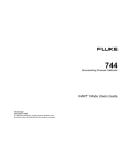
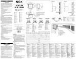
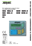
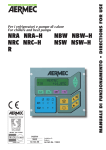
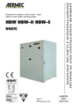
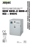
AFTER SALES SERVICE MANUAL
NXW
SOFTWARE VERS. 2.3
Please fill out the requested information
Please fill out the requested information
Summary
1
SOFTWARE VERSION......................................................................................................................................... 3
2
I/O CONFIGURATION ......................................................................................................................................... 3
PLAN SETTING ............................................................................................................................................................... 7
3
USER INTERFACE.............................................................................................................................................. 11
3.1
3.2
3.3
3.4
4
PUMP MANAGEMENT ..................................................................................................................................... 36
4.1
4.2
5
UNIT STATUS .......................................................................................................................................................
ON/OFF MENU ....................................................................................................................................................
SERVICE MENÙ ....................................................................................................................................................
MANUFACTURER MENÙ ......................................................................................................................................
REVERSING CYCLE GAS SIDE ...............................................................................................................................
REVERSING CYCLE WATER SIDE ..........................................................................................................................
REGULATION ..................................................................................................................................................... 42
5.1
5.2
5.3
5.4
CONDENSAZION CONTROL ..................................................................................................................................
TEMPERATURE CONTROL ....................................................................................................................................
MULTIFUNCTION INPUT .......................................................................................................................................
TOTAL RECOVERY ...............................................................................................................................................
6
ALARMS ............................................................................................................................................................... 46
7
START UP ............................................................................................................................................................. 51
8
PCO LOG .............................................................................................................................................................. 60
1 Softwares version
Ed
1
2
Software
AerChiller_1_8
AerChiller_1_9
Date
11/01/11
23/02/11
3
4
AerChiller_2_0
AerChiller_2_1
07/04/11
01/06/11
5
6
AerChiller_2_2
AerChiller_2_3
07/07/11
14/10/11
producer
Note
F. Fortin
First version
F. Fortin
2nd version. Software UPGRADE. BIOS 5.14 updating. Inserted
"BlackBox"
Antifreeze and condensation pressure control improvements
DK management. New BMS list addresses. New “black box”
management. Masks movement. Condenser antifreeze. 2 fans group for
E version.
Software improvements. Lon work version
Software improvements. New pumps rotation management
WARNING : on units with more electronic cards they
must have same software version
Input / Output configuration
I/O pCO3 Large
1-4 circ. 1-8 comp. 1-2 evap. 1-2 cond.
Analogue inputs
B1
B2
B3
B4
B5
B6
B7
B8
B9
Master
HP circuit 1
LP circuit 1
TWOUT evaporator
TWIN evaporator
TWOUTcondenser
HP circuit 2
LP circuit 2
multifunction input
Air ext. temperature
Slave
HP circuit 3
LP circuit 3
TWOUT evaporator
TWIN evaporator
TWOUT condenser
HP circuit 4
LP circuit 4
TWOUT evaporator COMMON SENSOR (option)
TWOUT condenser COMMON SENSOR (option)
B10
TWIN condenser
TWIN condenser
Digital inputs
ID1
ID2
ID3
ID4
ID5
ID6
ID7
ID8
ID9
ID10
ID11
ID12
ID13
ID14
ID15
ID16
ID17
ID18
HP circuit 1
LP circuit 1
On/off remote contact
HEAT / COOL remote contact
FL evaporator
CP1 protection circuit 1
CP2 protection circuit 1
Phase sequency control
HP circuit 2
LP circuit 2
CP1 protection circuit 2
CP2 protection circuit 2
MTP1 protection evaporator
MTP2 protection evaporator
MTP1 condenser / Ventilator circ. 1
MTP2 condenser / Ventilator circ. 2
FL condenser
Multifunction contact enable
HP circuit 3
LP circuit 3
FL evaporator
CP1 protection circuit 3
CP2 protection circuit 3
Phase sequency control
HP circuit 4
LP circuit 4
CP1 protection circuit 4
CP2 protection circuit 4
MTP1 protection evaporator
MTP2 protection evaporator
MTP1 condenser / Ventilator circ. 1
MTP2 condenser / Ventilator circ. 2
FL condenser
Digital outputs
NO1
NO2
NO3
NO4
NO5
NO6
NO7
NO8
NO9
NO10
NO11
NO12
NO13
NO14
NO15
NO16
NO17
NO18
Analogue output
Y1
Y2
Y3
Y4
CP1 circuit 1
CP2 circuit 1
CP1 circuit 2
CP2 circuit 2
Pump 1 condenser
Pump 2 condenser
Pump 1 evaporator
Alarm grave
Pump 2 evaporator
Solenoid liquid valve circuit 1
Solenoid liquid valve circuit 2
4 way valve circuit 1 (output always available on W/W too)
4 way valve circuit 2 (output always available on W/W too)
Recovery bypass valve circuit 1
Recovery bypass valve circuit 2
Antifreeze heater
Condenser fan 1
Condenser fan 2
CP1 circuit 3
CP2 circuit 3
CP1 circuit 4
CP2 circuit 4
Pump 1 condenser
Pump 2 condenser
Pump 1 evaporator
Alarm grave
Pump 2 evaporator
Solenoid liquid valve circuit 3
Solenoid liquid valve circuit 4
4 way valve circuit 1 (output always available on W/W too)
4 way valve circuit 2 (output always available on W/W too)
Recovery bypass valve circuit 3
Recovery bypass valve circuit 4
Antifreeze heater
Condenser fan 1
Condenser fan 2
0-10 Vdc Condenser Inverter pump signal
0-10 Vdc Evaporator Inverter pump signal
0-10 Vdc Inverter fan signal 1
0-10 Vdc Inverter fan signal 2
0-10 Vdc Condenser Inverter pump signal
0-10 Vdc Evaporator Inverter pump signal
0-10 Vdc Inverter fan signal 1
0-10 Vdc Inverter fan signal 2
Table 1 – IO pCO3 large
pCOe – Recovery (add.1)
Analogue inputs
B1
B2
B3
B4
Digital inputs
ID1
ID2
ID3
ID4
Digital outputs
NO1
NO2
NO3
NO4
pCOe
SIW-R
SUW-R
SUW-R2 (DK version)
SUCR common output recovery sensor (DK version)
FL
Solen valve circuit 1 from Recovery
Solen valve circuit 1 from Condenser
Solen valve circuit 2 from Recovery
Solen valve circuit 2 from Condenser
Analogue output
Y1
Table 2 – IO pCOe
pCOe n.2 – for DK version (add. 2)
Analogue inputs
B1
B2
B3
B4
pCOe
SUW2 (2° evap)
SUCE (common evap sensor )
SUWH2 (0ut condenser 2)
SUCC common condensers sensor
Digital inputs
ID1
ID2
ID3
ID4
Digital outputs
NO1
NO2
NO3
NO4
Analogue output
Y1
Table 3 – IO pCOe
pGD1 and pLan setting:
Three Displays PGD1 can be used:
UNIT DISPLAY 1 add. 32 on board
REMOTE DISPLAY 1 add. 31
DISPLAY ON SLAVE CARD add. 30
CONNECTION OF TWO NXW units on pLAN network
Connect the cards in parallel throught the pLAN (J11) and to set the PCO3s like
MASTER unit address pLAN = 1
SLAVE unit address pLAN = 2
PROCEDURE TO SET UP THE I/O BOARD
ADDRESS by PGD0-1
Usually on the Carel terminals pressing the 3 bottons UP DOWN and ENTER together for some
seconds it is possible to receive information about terminals and cards address.
enter
For almost 5 sec.
• the following screen is displayed:
Terminal Adr: 32
I/O Board Adr: 1
Pressing ENTER
enter
It appears
Terminal Config
Press ENTER
to continue
And pressing ENTER
enter
P:01
Trm1
Trm2
Trm3
•
Adr
32
None
None
Priv/Shared
Sh
--
Ok? No
In this screen the Enter button moves the cursor from one field to another, whereas the arrow
keys change the current value of the field. The mention P:01 in this case indicates that the I/O
board with address 1 has been selected. Trm are the display terminals connected to the
network; normally only the terminal with address 32 is present.
•
•
Select the connection mode with terminal 32 as “Sh” that is shared with all the pCO board
connected together. (“Pr” would instead mean that terminal display 32 can communicate only
with the pCO board with address 01)
To exit the configuration procedure and store, select the field 'Ok ? no' and use the cursor
keys to bring up the answer 'Yes', then press Enter. To exit without storing, simply wait for
some sec. without pressing a key.
Sometimes the controller (pco) can lose the pLan address
If the terminal does not receive the network synchronization message (token) for more than 10 sec,
it wipes the display out completely and posts this message:
NO LINK
Having this fault the LEDs I/O board can be off .
PROCEDURE TO SET UP THE I/O BOARD ADDRESS:
Press UP DOWN and ENTER and to modify the terminal address to 0
Terminal Adr: 0
I/O Board Adr: 1
Switch off and on the board voltage supply
Press ALARM and UP together for some seconds
Self test
Please wait
And by UP or DOWN to insert the correct address (usually 1)
pLan address :
0
UP :
increase
DOWN
decrease
ENTER : save and exit
PS: in case pressing ALARM and UP no screen appears probably there is a hardware
fault on the pco.
Switch off and on the board voltage supply and pressing the 3 bottons re-insert the
correct display address (32)
Terminal Adr: 32
I/O Board Adr: 1
Where we have to see that now the I/O board address is present
USER INTERFACE
UNIT STATUS
FUNCT MODE
WATER TEMP
COMPRESSORS IN OPERATION
UNIT DANISH VERSION
EVAPORATORS AND
CONDENSERS
WATER TEMP.
CIRCUIT 1
HP -LP
CP STATUS
CIRCUIT 1
HP -LP
CP STATUS
CIRCUIT 3
HP -LP
CP STATUS
CIRCUIT 4
HP -LP
CP STATUS
ACTUAL SET POINT / ACTUAL WATER TEMPERATURE UNDER CONTROL
STEPS REQUESTED
CAPACITY
REQUESTED
ACTUAL CAPACITY PRODUCED
MULTIFUNCTION CONTACT on ID18
FUNCTION SELECTED VALUE
TOTAL RECOVERY WATER TEMP
RECOVERT ENABLE
Y/N
CAPACITY REQUESTED %
MAIN MENU'
MAIN MENU: SUB MENU
SELECTION
ON-OFF MENU
ON-OFF UNIT
BOARD pLAN
ADDRESS
UNIT STATUS
STATUS REQUESTED
SET POINT
SET POINT MENU
ACTUAL SET POINT
MAIN COOLING SET POINT
SECOND COOLING SET POINT
MAIN HEATING SET POINT
SECOND HEATING SET POINT
HEAT / COOL MENU'
HEATING/COOLING SUB MENU
ACTUAL FUNCT.
MODE
CLOCK / TIMER MENU'
CLOCK AND TIMER SUB MENU
DAY, DATE, TIME SETTING
TIMER SETTING
SPECIAL TIMER
DIFFERENT SET POINTS HAVING TIMER
ENABLED
SPECIAL DAYS TO SET A DIFFERENT SET POINT ENABLED UNDER
TIMER
INPUT/OUTPUT
INPUT / OUTPUT SUB MENU
CIRCUIT 1
HP
LP
EVAPORATOR OUTLET TEMP
EVAPORATOR INLET TEMP
CONDENSER OUTLET TEMP
CIRCUIT 2
HP
LP
CONDENSER INLET TEMP
DIGITAL INPUTS STATUS
HP1 SWITCH
LP1 SWITCH
DIGITAL INPUTS STATUS
REMOTE ON-OFF CONTACT
REMOTE HEAT/COOL CONTACT
DIGITAL INPUTS STATUS
FLOW SWITCH
DISCHARGE CP1 THERM
DIGITAL INPUTS STATUS
DISCHARGE CP2 THERM
SERIOUS ALARM
DIGITAL INPUTS STATUS
HP2 SWITCH
LP2 SWITCH
DIGITAL INPUTS STATUS
DISCHARGE CP3 THERM
DISCHARGE CP4 THERM
DIGITAL INPUTS STATUS
THERM PROT EVAP PUMP 1
THERM PROT EVAP PUMP 2
DIGITAL INPUTS STATUS
THERM PROT COND PUMP 1
THERM PROT COND PUMP 2
DIGITAL INPUTS STATUS
CONDENSER FLOW SWITCH
DIGITAL OUTPUT
COMPRESSOR 1
COMPRESSOR 2
DIGITAL OUTPUT
COMPRESSOR 3
COMPRESSOR 4
DIGITAL OUTPUT
CONDENSER PUMP 1
CONDENSER PUMP 2
DIGITAL OUTPUT
ANTIFREEZE HEATER
SERIOUS ALARM
DIGITAL OUTPUT
EVAPORATOR PUMP 1
DIGITAL OUTPUT
SOLENOID LIQ VALVE CIRC 1
SOLENOID LIQ VALV CIRC 2
DIGITAL OUTPUT
4 WAY VALVE CIRC 1
3 WAY VALVE CIRC 2
SERVICE MENU'
MENU' SERVICE
MENU' UNDER PASSWORD : 0442
SERVICE SUB MENU': CHANGE LANGUAGE
LANGUAGE
SELECTION
SERVICE SUB MENU': INFORMATION
SOFTWARE INFORMATIONS
SOFTWARE VERSION
HARDWARE SOFTWARE INFOS
SERVICE SUB MENU': pLAN NETWORK
pLAN NETWORK
pLAN STATUS
SERVICE SUB MENU': WORKING HOURS
WORKING HOURS
EVAPORATOR PUMPS WORKING HOURS
COMPRESSORS WORKING HOURS
SERVICE SUB MENU': BMS CONFIGURATION
BMS
CONFIGURATION
SUPERVISOR
CONFIG.
PROTOCOL, BAUD RATE, SERIAL ADDRESS SETTING
ENABLE PROTOCOL LON WORKS
WHEN LON: PROTOCOL=CAREL,BAUDRATE 4800, ADDRESS
1
SERVICE SUB MENU': SERVICE PARAMETERS : COUNTER
SERVICE
PARAMETERS
COUNTER SELECTION
EVAPORATOR WATER PUMP 1
MAINTENANCE SET - RESET
COMP 1
MAINTENANCE SET - RESET
COMP 2
MAINTENANCE SET . RESET
COMP 3
MAINTENANCE SET - RESET
COMP 4
MAINTENANCE SET . RESET
CONDENSER PUMP 1
MAINTENANCE SET - RESET
CONDENSER PUMP 2
MAINTENANCE SET - RESET
SERVICE SUB MENU': SERVICE PARAMETERS : T. REGULATION
SETTINGS MANAGEMENT REGULATION
ENABLE HEATING-COOLING REMOTE
CONTACT
ENABLE REMOTE ON-OFF CONTACT
DIGITAL Y/N
SUPERVISOR
Y/N
UNIT CONTROL BY UNIT TERMINAL (pgd1)
Y/N
UNIT IS CONTROLLED ONLY VIA REMOTE COMMANDS
SENSOR WATER TEMPERATURE CONTROL
SELECTION
INLET/OUTLET
KIND OF
REGULATION : P or
PI
INTEGRAL TIME
COOLING TEMP
BAND
HEATING TEMP BAND
COOLING SETPOINT LIMITS
HEATING SETPOINT LIMITS
ANTIFREEZE EVAPORATOR ALARM
ANTIFREEZE CONDENSER ALARM
EVAPORATOR ANTIFREEZE SET POINT
BY ELECTRIC HEATER
BY WATER PUMP. UNIT IN STAND BY ONLY
CONDENSER ANTIFREEZE SET
POINT
BY ELECTRIC HEATER
BY WATER PUMP. UNIT IN STAND BY ONLY
ANTIFREEZE PREVENT
COMPRESSORS ARE FORCED OFF
TIME BETWEEN 2 COMPRESSORS START
TIME BETWEEN 2 COMPRESSORS STOP
EVAPORATOR PUMPS NUMBER
MAX NUMBER OF FLOW SWITCH PRE-ALARM
AFTER 7 DAYS WITHOUT TO START, PUMP
IS SWITCHED ON 30 SECONDS
CONDENSER PUMPS NUMBER
MAX NUMBER OF FLOW SWITCH PRE-ALARM
EVAPORATOR PUMP
DELAY TIME BETWEEN PUMP AND COMPR START
DELAY TIME TO STOP PUMP AFTER COMPR STOP
EVAPORATOR FLOW SWITCH ALARM
DELAY TIME AFTER PUMP START
RUNNING DELAY TIME
EVAPORATOR PUMP
PUMPS ROTATION TIME
COMMON RUNNING TIME
CONDENSER PUMP
PUMP ON : COMPRESSOR ON / UNIT ON
DELAY TIME TO START PUMP AFTER COMPR START
DELAY TIME TO STOP PUMP AFTER COMPR STOP
CONDENSER FLOW SWITCH
ALARM
DELAY TIME AFTER PUMP START
RUNNING DELAY TIME
CONDENSER PUMP
PUMPS ROTATION TIME
COMMON RUNNING TIME
COOLING PRESSURE CONDENSATION
CONTROL
SET
POINT
DIFFERENTIAL
CPE PUMP MANAGEMENT
IN COOLING MODE: USER PLANT
HEATING MODE: EXT. CIRC (WELL, GEOTH, DRYCOOL, H VERSION) /
USER
INVERTER PUMP / VALVE USER CIRCUIT
FIXED SIGNALS
INVERTER PUMP/VALVE EXTERNAL CIRCUIT COOLING CONTROL
MIN SPEED/VOLTAGE
MAX SPEED/VOLTAGE
INVERTER PUMP/VALVE EXTERNAL CIRCUIT COOLING CONTROL
CONDENSATION PRESSURE CONTROL BY HP
TRASDUCER
INVERTER PUMP/VALVE EXTERNAL CIRCUIT COOLING CONTROL
MIN / MAX SIGNAL VOLTAGE
INVERTER PUMP/VALVE EXTERNAL CIRCUIT HEATING CONTROL
FIXED SIGNAL
INVERTER PUMP/VALVE EXTERNAL CIRCUIT COOLING CONTROL
BY OUTLET WATER TEMP
SET, DIFFERENTIAL, INTEGRAL
TIME
INVERTER PUMP/VALVE EXTERNAL CIRCUIT HEATING CONTROL
FIXED SIGNAL
INVERTER PUMP/VALVE EXTERNAL CIRCUIT HEATING CONTROL
BY OUTLET WATER TEMP
SET, DIFFERENTIAL, INTEGRAL
TIME
ENABLE TOTAL RECOVERY
TOTAL RECOVERY
DIFFERENTIAL BAND
MAX OUTLET WATER TEMP ON RECOVERY
SIDE
TOTAL RECOVERY
MIN RECOVERY OFF TIME
MULTIFUNCTION CONTACT
ENABLE INPUT B8
MULTIFUNCTION CONTACT
INPUT CONFIG: POWER LIMIT/ POWER DEMAND / VARIABLE SET POINT
TYPE: 0-10 VOLT / NTC / 4-20 Ma
MULTIFUNCTION CONTACT
CONFIG: NTC
MIN / MAX TEMP
MULTIFUNCTION CONTACT
CONFIG: POWER LIMIT
MIN / MAX %
MULTIFUNCTION CONTACT
CONFIG: POWER DEMAND
MIN / MAX %
MULTIFUNCTION CONTACT
CONFIG: VARIABLE SET POINT-COOLING
MIN / MAX SET POINT
MULTIFUNCTION CONTACT
CONFIG: VARIABLE SET POINT-HEATING
MIN / MAX SET POINT
SERVICE SUB MENU': SERVICE PARAMETERS : MANUAL MANAGEMENT
COMPRESSORS CAN MANUALLY FORCED OFF
UNIT IN STAND BY
ONLY
COMPRESSORS CAN
FORCED ON
SOLENOID LIQUID VALVES CAN FORCED ON
UNIT IN STAND BY
ONLY
EVAPORATOR PUMPS CAN FORCED ON
UNIT IN STAND BY
ONLY
CONDENSER PUMPS CAN FORCED ON
UNIT IN STAND BY
ONLY
4 WAY VALVES CAN
FORCED ON
UNIT IN STAND BY
ONLY
ANTIFREEZE ELECTRIC HEATER CAN FORCED
ON
SERVICE SUB MENU': SERVICE PARAMETERS : DEFAULT RESET /CHANGE PASSWORD
CHANGE USER PASSWORD
USER PARAMETERS DEFAULT
RESET: Y/N
DATE OF LAST
RESET
SERVICE SUB MENU': SERVICE PARAMETERS : CONFIGURATION
UNIT SELECTION:
WATER / WATER
AIR / WATER (CONDENSER ON
AIR SIDE)
WATER / WATER HEAT PUMP
WATER / WATER ONLY
CHILLER
TYPE OF CONDENSATION:
SINGLE: COND PRESS CONTROLLED ON HIGHER HP BY NO17
AND Y3(0-10V)
SEPARATED: EVERY CIRCUIT CONTROLS OWN HP
BY NO17-Y3 ON CIRC1
AND NO18-Y4 ON CIRC2
TYPE OF REVERSING CYCLE: WATER / GAS
REFRIGERANT TYPE
NUMBER OF REFRIGERANT CIRCUITS
NUMBER OF COMPRESSORS PER CIRCUIT
UNIT DANISH VERSION: Y/N
2 EVAPOR / 2 CONDENS.
MANUFACTURER MENU'
INSERT NEW MANUFACTURER PASSWORD
MANUFACTURER SUB MENU': I/O CONFIGURATION
TEMP SENSOR CONFIGURATION
ENABLE AIR EXTERNAL TEMP SENSOR
MANUFACTURER SUB MENU': MANUFACTURER PARAMETERS
DATA FORMAT:
GG / MM / AA
COMPRESSORS
TIME MIN ON
TIME MIN OFF
TIME MIN BETWEEN 2 SAME COMPRESSOR STARTS
ENABLE PREVENT ALARMS FUNCTION
HIGH PRESSURE Y/N (COMP SWITCHED OFF)
LOW PRESSURE Y/N (COMP SWITCHED OFF
ANTIFREEZE Y/N (COMP SWITCHED OFF)
ANTIFREEZE COMPRESSORS FORCE OFF
OFFSET FROM ANTIFREEZE SET POINT
DIFFERENTIAL
LOW PRESSURE LOW ALARM
SET
BY PASS TIME AFTER COMPRESSORS START
LOW PRESSURE ALARM
SET
DIFFERENTIAL
LOW PRESSURE ALARM
DELAY TIME AFTER COMPRESSOR START
HIGH PRESSURE ALARM
SET
DIFFERENTIAL
HIGH PRESSURE PREVENT
SET
DIFFERENTIAL
HIGH PRESSURE PREVENT
MAX PREVENT
NUMBER
PREVENT DELAY TIME
LOW PRESSURE PREVENT
SET
DIFFERENTIAL
LOW PRESSURE PREVENT
MAX PREVENT
NUMBER
PREVENT DELAY TIME
ANTIFREEZE PREVENT
MAX PREVENT
NUMBER
PREVENT DELAY TIME
MANUFACTURER SUB MENU': MANUFACTURER DEFAULT RESET
INSERT NEW MANUFACTURER PASSWORD
RESET MANUFACTURER PARAMETERS
BASE MODEL PARAMETERS ARE UPDATED, THEN UNIT MUST BE
CORRECTELY SETTED
WARNING MESSAGE: RESET DONE
POWER OFF AND RESTART CONTROLLER
SAVE
CONFIGURATION
IT'S POSSIBLE TO SAVE LAST PARAMETERS CONFIGURATION
UNIT CONFIGURATION
GROUP
A
B
C
D
TYPE OF UNIT
E-VERSION (only
Evaporator)
UNIT WITH
REVERSING
CYCLE ON GAS
SIDE
ORIGINAL
PARAM.
SETTING
NEW
PARAMETER
ADJUSTED
MENU
(Prg button)
UNIT SELECTION:
WATER / WATER
AIR / WATER
SERVICE
CONFIGURATION
PSW 0442
UNIT SELECTION:
CHILLER
CHILLER
SERVICE
CONFIGURATION
PSW 0442
TYPE OF
CONDENSATION
SINGLE or
SEPARATED
SERVICE
CONFIGURATION
PSW 0442
TYPE OF
REVERSING
CYCLE:
GAS
SERVICE
CONFIGURATION
PSW 0442
TOTAL RECOVERY:
YES
SERVICE
SERV. PARAM
TH. REGULATION
PSW 0442
REVERSING CYCLE:
UNIT TOTAL
RECOVERY
VERSION
Pcoe dip switch
setting:
dip 1 = ON
dip2 = OFF
dip3 = OFF
dip4 = OFF
DK version
2 evap
2 cond
Pcoe dip switch
setting:
dip 1 = OFF
dip2 = ON
dip3 = OFF
dip4 = OFF
DK version
SERVICE
CONFIGURATION
PSW 0442
ANTIFREEZE ALARM
ANTIF. ALARM: 10°C
SERVICE
SERV. PARAM
TH. REGULATION
PSW 0442
COOLING SET
POINT LIMIT
LOW LIMIT:
-8°C
SERVICE
SERV. PARAM
TH. REGULATION
PSW 0442
ANTIFREEZE
HEATER
SETPOINT:
-8°C
SERVICE
SERV. PARAM
TH. REGULATION
PSW 0442
ANTIFREEZE
PREVENT
SETPOINT:
-9.4°C
SERVICE
SERV. PARAM
TH. REGULATION
PSW 0442
COOLING SET
POINT 1
SETPOINT:
-6°C
SET POINT
Y version
E
Pumps management
Unit with reversing cycle gas side
Pumps on board or not
Cooling mode
P1
P2
P1: User pumps: ON-OFF or adjustable with fixed speed
P2: External pump adjustable to condensation control (HP) or water temperature control
Heating mode
P1
P2
P1: User pumps: ON-OFF or adjustable with fixed speed
P2: External pump adjustable to water temperature control or fixed speed
Parameter setting to control this kind of installation
See: Errore. L'origine riferimento non è stata trovata.
P1: It is possible to set a fix speed on user
inverter pump in cooling and heating mode.
P2: In caso inverter pump on external circuiti
s presenti t is possible to set the
CONDENSATION PRESSURE CONTROL or
OUTLET
WATER
TEMPERATURE
CONTROL
Unit with reversing cycle water side
Pumps on board or not but before the water valves
Cooling mode
P1
P2
P1: User pumps: ON-OFF or adjustable with fixed speed
P2: External pump adjustable to condensation control (HP) or water temperature control
Heating mode
P1
P2
P1: External pump adjustable to water temperature control or fixed speed
P2: User pumps: ON-OFF or adjustable with fixed speed
Parameter setting to control this kind of installation
See: Errore. L'origine riferimento non è stata trovata.
P1: Evaporator pump in cooling is always on
USER side. In heating is on external circuit
side it means that water valves are installed
after the pumps so P1 is always evaporator
pump.
In case inverter pump on USER side is
possible to set fix speed for cooling mode P1.
In heating will be P2 that works with fixed
speed.
When inverter pump/Valve is on external
circuiti t is possible to choose the control HP
by
CONDENSATION
PRESSURE
CONTROL or controlling the OUTLET
WATER TEMPERATURE.
On first case pump speed P2 is adjusted to
have the HP set point setted. In cooling while
in heating will have fixed speed.
On second case by water temp control, P2
speed will aduste in cooling mode while P1
will adjusts speed in heating to control the
outlet water temp.
In case inverter pump is on external circuiti s
possible to set a fixed speed in heating fot
the pump P2.
PUMPS NOT ON BOARD BUT AFTER WATER VALVES
Cooling mode
P1
P2
P1: User pumps: ON-OFF or adjustable with fixed speed
P2: External pump adjustable to condensation control (HP) or water temperature control
Heating mode
P2
P1
P1: : User pumps: ON-OFF or adjustable with fixed speed
P2: Variable speed pump on ecternal circuit to control water temp or with fixed speed
Parameters to adjust to control this kind of plant
See: Errore. L'origine riferimento non è stata trovata.
P1: The evap pump in cooling is always on
USER side. If in heating mode pump serves
the user circuit it means that valve is before
the pump so P1 supplies the evaporator in
cooling and condenser in heating
Viceversa P2 supplies condenser in cooling
and evaporator in heating
P1: Inverter pump on USER side. It is
possible to set fixed speed on both
functioning mode.
When inverter pump is on external circuiti s
possible to set the HP control by
CONDENSATION
PRESSURE
or
by
OUTLET TEMPERATURE.
By CONDENSATION PRESSURE P2
change speed to satisfy the HP setted while
will work with fixed speed in heating.
By OUTLET WATER TEMPERATURE
CONTROL P2 speed is adjusted in cooling
while P1 adjusts speed in heating to arrive at
the temperature requested.
In case inverter pump P2 is on external side
is possible to set fixed speed in heating mode
Regulation
1.1 Double pump management
From 2.3 SW versioni s possible to manage the pumps rotation by TIME SETTED or in
case of ALARM ( second pump will be immediately activated)
1.2 Condensation control
To control the HP pressure is used an analoge output 0-10V. It is necessary to set the HP
setpoint and differential, the minimum and maximum speed. The regulation is
PROPORTIONAL.
The regulation is done following the circuit with higher HP.
Volt
Max
speed
Min
speed
Differential
Setpoint
HP trasducer
1.3 Temperature control
It is also possible control the pumps speed according to the OUTLET WATER TEMP
(condenser side, well water, geothermic plant, Drycoolers). The regulation is PI setting the
integral time or only PROP if integral time = 0.
Volt
Max
speed
Min
speed
Well
Water
Temp control
Prop or Prop +
int
Differential
Setpoint
Volt
Max
speed
Min
speed
Well
Water
temp
control
(P or PI)
Differential
Setpoint
1.4 Multifunction contact
B8 is used like multifunction input
Enable this function on
Selecting the type of input, then the max e min limits used.
Ex. 4-20mA to control POWER produced select POWER DEMAND type of input 4-20mA
and the min limit at 4 mA and max limit at 20mA.
Power demand
Max
100%
Min
0%
Min
4mA
Max
20mA
Multifunction
input
1.5 Total recovery
This type of unit has a third exchanger that can be used ONLY IN COOLING MODE.
Recovery activation is done by 3 way valve (see Table 1 – IO pCO3 large). 2 water probes
read the IN-OUT water temperatures. Control is done by SETPOINT and DIFF setted
Recovery capacity demand
100%
Circ 2
REC on
50%
Circ 1
REC on
Twin-R
Setpoint
1.6 Antifreeze management
For UNIT Y version able to produce water up to -6°C parameters have to be adusted:
A: MIN COOLING SET POINT LIMIT
B: ANTIFREEZE ALARM
C: ANTIFREEZE ELECTRIC HEATER SETPOINT
D: ANTIFREEZE PREVENT SETPOINT
2 Alarms
2.1 Alarms and prevent: High, Low pressure and Antifreeze
Prevent is a limit to force off compressor. If after 10 sec (fixed time not adjustable) we are
under/over limit a compressori s force off. Procedure is repeated until to have only one
compressor in operation. Prevent calls can be setted by parameter but if this number is
satisfy in a certain time (60 minutes not adjustable) unit will stay in operation untill to reach
alarm limit
2 bar
2 bar
Prevent
Alarm
36
(Bar):
37
2 bar
2 bar
Prevent
Alarm
(Bar):
HP
39
38
2
2.5
3
LP
1°
1°
Alarm/
Force off
(°C):
3
3.6
Prevent
4
4.6
TWout
2.2 Low pressure alarm LOW
The LP LOW alarm stop the compressors start when refrigerant pressure is too low
(refrigerant circuits empty). Unit tries to start one by one the compressors before to go on
alarm.
CP1
CP2
LP
AL75 - LP LOW
LP < 1,6bar
AL035
alarm
–
LP
2.3 Alarms table
Codice
Allarme
Descrizione
ALG01
Clock board broken or not connected
ALG02
Expansion memory damaged
ALR03
Grave Alarm by (ID8) Phase monitor
ALO04
Slave offline Check J10 and J11 if are connected
ALA05
HP1 trasducer broken or not connected
ALA06
HP2 trasducer broken or not connected
ALA07
HP3 trasducer broken or not connected (SLAVE)
ALA08
HP4 trasducer broken or not connected (SLAVE)
ALA09
LP1 trasducer broken or not connected
ALA10
LP2 trasducer broken or not connected
ALA11
LP3 trasducer broken or not connected (SLAVE)
ALA12
LP4 trasducer broken or not connected (SLAVE)
ALA13
Evap inlet water probe broken or not connected
ALA14
Cond inlet water probe broken or not connected
ALA15
Evap outlet water probe broken or not connected
ALA16
Evap outlet water probe 1 broken or not connected (DK version)
ALA17
Evap outlet water probe 2 broken or not connected (DK version)
ALA18
Evap outlet water probe 3 broken or not connected (DK version) (SLAVE)
ALA19
Evap outlet water probe 4 broken or not connected (DK version) (SLAVE)
ALA20
Cond outlet water probe broken or not connected
ALA21
Cond outlet water probe 2 broken or not connected
ALA22
Cond outlet water probe 3 broken or not connected (SLAVE)
ALA23
Cond outlet water probe 4 broken or not connected (SLAVE)
ALA24
Sonda temperatura acqua evaporatore rotta o non connessa
ALA25
Evap temperature probe broken or not connected
ALT26
Maintenance CP1 maintenance countdown is finished
ALT27
Maintenance FAN GROUP 1. maintenance countdown is finished
ALT28
Maintenance Condenser PUMP. maintenance countdown is finished
ALT29
Maintenance Evaporator PUMP. maintenance countdown is finished
ALC30
Thermal compressor 1
ALW31
Compressors circ 1 forced off by antifreeze limit
ALW32
End defrost for max time Circ.1:
ALW33
End pump-down for max time Circ.1:
ALB34
Low pressure alarm by pressure switch Circ.1:
ALB35
Low pressure alarm by trasducer Circ.1:
ALB36
High pressure alarm by pressure switch Circ.1:
ALB37
High pressure alarm by trasducer Circ.1:
ALP38
Warning Flow switch evaporat. P1
ALP39
Warning Flow switch evaporat. P2
ALP40
Flow switch evaporat. P1
ALP41
Flow switch evaporat. P2
ALP42
Thermal protection evap. Pump P1
ALP43
Thermal protection evap. Pump P2
ALP44
Warning Flow switch conden. P1
ALP45
Warning Flow switch conden. P2
ALP46
Flow switch conden. P1
ALP47
Flow switch conden. P2
ALB48
Antifreeze Circ.1:
ALB49
Antifreeze Circuit 1 e 2 or Circuit 3 e 4:
ALU50
Unit Antifreeze alarm
ALB51
Warning circ.1 HP / LP / Antifreeze
ALB52
Warning circ.2 HP / LP / Antifreeze
ALB53
Warning circ.3 HP / LP / Antifreeze (SLAVE)
ALB54
Warning circ.4 HP / LP / Antifreeze (SLAVE)
ALB55
Warning Antifreeze Circuit 1 e 2 or Circuit 3 e 4:
ALU56
Warning unit Antifreeze
AL63
Therm. Protection Condenser pump1
AL64
Therm. Protection Condenser pump2
AL65
Therm. Protection VENT1
AL66
Therm. Protection VENT2
AL67
Flow switch evaporat. P1 Slave
AL68
Flow switch evaporat. P2 Slave
AL69
Warning Flow switch evaporat. P1 Slave
AL70
Warning Flow switch evaporat. P2 Slave
AL71
Flow switch conden. P1 Slave
AL72
Flow switch conden. P2 Slave
AL73
Warning Flow switch conden. P1 Slave
AL74
Warning Flow switch conden. P2 Slave
AL75
LP Low Circuit 1
AL76
LP Low Circuit 2
AL77
LP Low Circuit 3 (SLAVE)
AL78
LP Low Circuit 4 (SLAVE)
AL79
Thermal protection evap. P1 (SLAVE)
AL80
Thermal protection evap. P2 (SLAVE)
AL81
Evap outlet water probe broken or not connected (slave)
AL82
Evap common outlet water probe broken or not connected (slave)
AL83
Cond. common outlet water probe broken or not connected (slave)
AL84
Therm. Protection Condenser pump1 (slave)
AL85
Therm. Protection Condenser pump2 (slave)
AL86
Evap inlet water probe broken or not connected (slave)
AL87
Cond. inlet water probe broken or not connected (slave)
AL88
Cond. outlet water probe broken or not connected (slave)
AL89
pCOe: pCOe offline
AL90
pCOe: Analogic inlet probe Ch. 1 broken or not connected
AL91
pCOe: Analogic inlet probe Ch. 2 broken or not connected
AL92
pCOe: Analogic inlet probe Ch. 3 broken or not connected
AL93
pCOe: Analogic inlet probe Ch. 4 broken or not connected
AL94
pCOe: I/O alarm mismatch (no confirm of for 10s)
AL95
pCOe Slave: offline
AL96
pCOe Slave: Analogic inlet probe Ch. 1 broken or not connected
AL97
pCOe Slave: Analogic inlet probe Ch. 2 broken or not connected
AL98
pCOe Slave: Analogic inlet probe Ch. 3 broken or not connected
AL99
pCOe Slave: Analogic inlet probe Ch. 4 broken or not connected
AL100
pCOe Slave: I/O alarm mismatch (no confirm of pattern for 10s)
AL101
pCOe number 2: Offline (exp probes DK version)
Al102
pCOe number 2: Analogic inlet probe Ch. 1 broken or not connected (exp probes DK version)
AL103
pCOe number 2: Analogic inlet probe Ch. 1 broken or not connected (exp probes DK version)
AL104
pCOe number 2: Analogic inlet probe Ch. 1 broken or not connected (exp probes DK version)
AL105
pCOe number 2: Analogic inlet probe Ch. 1 broken or not connected (exp probes DK version)
AL106
pCOe number 2: : I/O alarm mismatch (no confirm of for 10s) (exp probes DK version)
START UP
Before starting the chiller, the external hydraulic system going to the unit and the pipe
connections should be checked; remove any contaminating matter and make sure that the water
pipes are properly supported.
If the unit does not feature a hydronic kit, the following must be installed to prevent the warranty
from becoming null and void: FLOW SWITCH and MECHANICAL FILTER; the mesh hole
diameter must be </= 1 mm
A flow switch and a kit are installed on the machine in the models that feature a hydronic kit, but
the following should be installed on the external hydraulic circuit:
-
Pressure gauges
Antivibration couplings
Stop valves
Safety valve
After checking the appropriateness of the hydraulic system, fill the system (1-2 bar) and check the
air bleeds.
If necessary, due to the working temperature, a suitable quantity of glycol will be added; the glycol
must not be released in the surrounding environment when maintenance activities are carried out.
The electrical wiring requirements must be met.
Voltage should not vary by +/-10% compared to the rated value and the unbalance between the
phases should not exceed 3%.
The following is compulsory:
-
Use double-insulation cables in accordance with the standards in force
Install a magnetothermal switch
Proper cable grounding
Make sure that the power conductor terminals are tight (after 30 days and every 6 months)
81
Recommended cable section for a max. cable length of 50 metres
82
Start-up data table
Unit:………………………………………………………………..……….…
Serial No.…………………………………………………………….………..
Accessories installed………………………………………………………..…
NOTES:
……………………………………………………………………………………
……………………………………………………………………………...........
…………………………………….……………………………………….…….
……………………………………………………………………………………
……………………………………………………………………………………
1.2
ENERA
DESCRIPTION
CIRC. 1
CIRC. 2
NOTES
L
1. Preliminary procedures
1.1. Cables section
1.2. Earthing:
1.3. Cable fastening:
1.4. Rated volt value:
1.5. Voltage downstream of
the main switch:
1.6. Display activation:
1.7. External connections:
1.8. Compressor
resistances
2. Hydraulic circuit
guarding
2.1. Hydraulic connections:
2.2. Water filter
83
2.3. Hydraulic circuit:
2.4. Valves:
2.5. Pumps:
2.6. Water flow rate:
2.7. Flow switch:
2.8. Cleaning:
2.9. Glycol:
3. Start UP
3.1. Unit start-up:
3.2. Set Points:
3.3. Phase rotation:
3.4. Rated current
(as per catalogue):
3.5. Rated Freon load
3.6. High pressure
3.7. Low pressure
3.8. Solenoid
water
temperature
3.9. CN water temperature
3.10. Current absorbed by
compressors
3.11. Current absorbed by
pumps
3.12. Leaks:
3.13.
Oil level:
3.14.
Overheating:
3.15.
Undercooling
84
3.16.
Pressing temperature:
4. SAFETY DEVICES
4.1. General:
4.2. HIGH PRESSURE:
4.3. LOW PRESSURE
4.4. ANTIFREEZE
4.5. CP
SWITCH
4.6. PUMP
SWITCH
THERMAL
THERMAL
85
MAINTENANCE:
Scheduled maintenance is essential to preserve the efficiency of the unit.
The following is recommended:
HYDRAULIC CIRCUIT:
- Fill and drain the hydraulic system
- Clean the water filter
- Check the flow switch
- Check the water flow rate
- Check the pipe insulation
- Check glycol
ELECTRICAL SYSTEM:
- Efficiency of safety devices
- Check the power supply
- Electrical absorption
- Make sure that the terminals are tight
- Check the compressor oil resistance
CHILLING SYSTEM:
- Compressor conditions
- Check the antifreeze resistance
- Working pressure
- Test the leak detector
- Check the safety devices
MECHANICAL CHECKS:
- Make sure that the screws are tight
- Check for noise or vibration
- Check the overall structure
86
TABLES R410A
87
88
PCO Log management
On software AerChiller (since version 1.8) actually on NXW series there is a new data
logging function to help diagnostic during failure analysis.
It is a pCO3 internal memory that recorder factory datas selected.
Memory it isn’t so big so actually all probes and digital I/O are recordered every 2 seconds
and using this setting 7 working hours datas can be saved.
Next working hours will be re-write (circolar logic). From SW version 2.1 data recording write
is stopped when an alarm occured to restart after alarm manual reset.
There is a stop data writing option in order to have working parameters datas before an
alarm. This is done to help the recovery-data and to have complete information about
faults.
Log Enable
After an alarm except one of the list above it is necessary to enable the log for next logging
How to re-set the log:
1. ATTENTION : Unit must be in standby , VERY DANGEROUS because software
can be damaged losing safeties control.
2. No ALARMS ACTIVATED because the log would be immediately blocked by the
actual alarm not resetted.
3. Press AL + “Enter” up to see following mask
¾ SYSTEM INFORMATION
LOG DATA
OTHER INFORMATION
4. By “DOWN” select LOG DATA
SYSTEM INFORMATION
¾ LOG DATA
OTHER INFORMATION
90
5. Press “ENTER”
1
DISPLAY LOG DATA
Wich memory
INTERNAL MEMORY
6. Press “ENTER”
5
Log status : DISABLED
UP or DOWN: change
7. Press “DOWN” or “UP” to ENABLE the log. Now log is activated and it starts to
recorder up to next alarm.
From version 2.1 this procedure is by-passed because the reset is done AUTOMACTELY
2 Download of ALARM MEMORY by SmartKey
Procedure:
1.
2.
3.
4.
5.
6.
7.
8.
Powered OFF the pCO
Connect the SmartKey removing display connection
Powered IN the pCO
Wait to see on the SmartKey the “paper” symbol
Press “Start” to start datas dowload
When download is finished a “bip” comes out
Powered OFF the pCO and reconnect the display
Datas are now on SmartKey and by pc can be analyzed.
91
3 Download ALARM MEMORY from SmartKey to PC
Tools:
-
Carel SmartKey
-
Carel SmartKey USB Adapter
-
Software SmartKey Programmer
92
Procedure:
1. Connect the SmartKey to the SmartKey USB Converter (cod. Carel PCOS00AKC0)
2. Start software SmartKey Programer and next window appears
3. Press “GO”
4. Enter on area “Memory alarm”. And next windows appears
93
5. Select directory where to save files on red circle showed below
6. Select on left list the log data that must saved in the PC by red indicator showed
below and check that datas moved on right list.
94
7. Press Download to start transfer procedure.
8. On left corner a bar shows download. When download is finished Press than OK
and closed application.
Now by Excel datas can be analyzed. Importing datas present on
“BlackBoxEvent_GRAPH.csv” graphics can be created.
Datas follows Comma separated Value. On Excel to use “Data->Imported external
data” and select file “BlackBoxEvent_GRAPH.csv” on directory before selected at
point 5.
Select options showed below.
Select interested datas and make a graph by (XY).
96