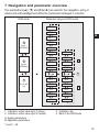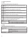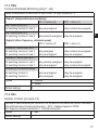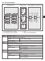
1
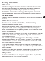
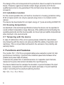
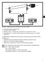
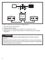
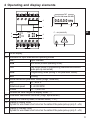
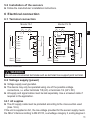
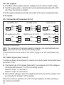
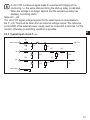
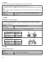
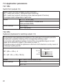
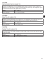
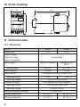
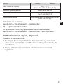
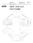
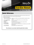
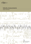
Operating instructions
7390958 / 00
01 / 2013
Monitor
FS-1 / FS-1N
UK
Contents
1 Preliminary note���������������������������������������������������������������������������������������������������4
1.1 Symbols used������������������������������������������������������������������������������������������������4
1.2 Warning signs used���������������������������������������������������������������������������������������4
2 Safety instructions�����������������������������������������������������������������������������������������������5
2.1 General����������������������������������������������������������������������������������������������������������5
2.2 Target group���������������������������������������������������������������������������������������������������5
2.3 Electrical connection��������������������������������������������������������������������������������������5
2.4 Operation�������������������������������������������������������������������������������������������������������5
2.5 Installation location����������������������������������������������������������������������������������������6
2.6 Housing temperature�������������������������������������������������������������������������������������6
2.7 Tampering with the device�����������������������������������������������������������������������������6
3 Functions and features����������������������������������������������������������������������������������������6
4 Operating and display elements��������������������������������������������������������������������������9
4.1 Display stand-by mode��������������������������������������������������������������������������������10
5 Installation���������������������������������������������������������������������������������������������������������10
5.1 Installation of the device������������������������������������������������������������������������������10
5.2 Installation of the sensors ��������������������������������������������������������������������������� 11
6 Electrical connection������������������������������������������������������������������������������������������ 11
6.1 Terminal connection������������������������������������������������������������������������������������� 11
6.2 Voltage supply (power)�������������������������������������������������������������������������������� 11
6.2.1 AC supplies����������������������������������������������������������������������������������������� 11
6.2.2 DC supplies����������������������������������������������������������������������������������������12
6.3 Inputs�����������������������������������������������������������������������������������������������������������12
6.3.1 Connection of the sensors (In1, 2)�����������������������������������������������������12
6.3.2 Reset inputs (reset 1 and 2)���������������������������������������������������������������12
6.3.3 Typical input circuit F...-x��������������������������������������������������������������������13
6.4 Outputs��������������������������������������������������������������������������������������������������������14
6.4.1 Relay outputs (Out1, 2)����������������������������������������������������������������������14
6.4.2 Transistor outputs (Out1, 2)����������������������������������������������������������������14
6.5 Additional outputs for NAMUR devices (F...-xN)������������������������������������������14
6.5.1 Fault outputs���������������������������������������������������������������������������������������14
7 Navigation and parameter overview������������������������������������������������������������������15
7.1 System parameters�������������������������������������������������������������������������������������16
2
7.1.1 FOx�����������������������������������������������������������������������������������������������������16
7.1.2 SOx�����������������������������������������������������������������������������������������������������16
7.1.3 FWx����������������������������������������������������������������������������������������������������17
7.1.4 NCx�����������������������������������������������������������������������������������������������������17
7.1.5 EF1�����������������������������������������������������������������������������������������������������18
7.1.6 MF1����������������������������������������������������������������������������������������������������18
7.1.7 DF1�����������������������������������������������������������������������������������������������������18
7.1.8 DIM�����������������������������������������������������������������������������������������������������19
7.1.9 VER����������������������������������������������������������������������������������������������������19
7.2 Application parameters��������������������������������������������������������������������������������20 UK
7.2.1 SPx�����������������������������������������������������������������������������������������������������20
7.2.2 HYx�����������������������������������������������������������������������������������������������������20
7.2.3 STx�����������������������������������������������������������������������������������������������������21
7.2.4 DTx�����������������������������������������������������������������������������������������������������21
7.2.5 FTx�����������������������������������������������������������������������������������������������������21
8 Programming�����������������������������������������������������������������������������������������������������22
8.1 Programming example DT1 (Delay Time, output 1)������������������������������������22
8.2 Notes on programming��������������������������������������������������������������������������������23
8.2.1 RUN mode������������������������������������������������������������������������������������������23
8.2.2 Time Out Function������������������������������������������������������������������������������23
8.2.3 Numerical entries��������������������������������������������������������������������������������23
8.2.4 Factory Reset�������������������������������������������������������������������������������������24
8.2.5 KEY function (locking)������������������������������������������������������������������������24
9 Test mode����������������������������������������������������������������������������������������������������������25
9.1 Activate the test mode���������������������������������������������������������������������������������25
9.2 Terminate the test mode������������������������������������������������������������������������������25
9.3 Test parameters�������������������������������������������������������������������������������������������26
10 Scale drawing��������������������������������������������������������������������������������������������������27
11 Technical data��������������������������������������������������������������������������������������������������27
11.1 Overview����������������������������������������������������������������������������������������������������27
11.2 Approvals/standards����������������������������������������������������������������������������������28
12 Maintenance, repair, disposal��������������������������������������������������������������������������28
This document is the original instructions.
3
1 Preliminary note
This document is part of the device and contains information about the correct
handling of the product.
This document is intended for specialists. These specialists are people who are
qualified by their training and their experience to see risks and to avoid possible
hazards that may be caused during operation or maintenance of the device.
Read this document before use to familiarise yourself with operating conditions,
installation and operation. Keep this document during the entire duration of use of
the device.
Adhere to the warning notes and safety instructions.
1.1 Symbols used
►
>
[…]
→
Instruction
Reaction, result
Designation of pushbuttons, buttons or indications
Cross-reference
Important note
Non-compliance can result in malfunction or interference.
Information
Supplementary note.
1.2 Warning signs used
WARNING
Warning of serious personal injury.
Death or serious irreversible injuries may result.
CAUTION
Warning of personal injury.
Slight reversible injuries may result.
NOTE
Warning of damage to property.
4
2 Safety instructions
2.1 General
Follow the operating instructions. Non-observance of the instructions, operation
which is not in accordance with use as prescribed below, wrong installation or
incorrect handling can affect the safety of operators and machinery.
The installation and connection must comply with the applicable national and
international standards. Responsibility lies with the person installing the device.
2.2 Target group
UK
The device must only be installed, connected and put into operation by a qualified
electrician.
2.3 Electrical connection
Disconnect the unit externally before handling it. Also disconnect any
independently supplied relay load circuits.
Make sure that the external voltage is generated and supplied according to the
requirements for safe extra-low voltage (SELV) since this voltage is supplied
without further measures near the operating elements and at the terminals for the
supply of connected sensors.
The wiring of all signals in connection with the SELV circuit of the device must also
comply with the SELV criteria (safety extra-low voltage, safe electrical isolation
from other electric circuits).
If the externally supplied or internally generated SELV voltage is externally
grounded, the responsibility lies with the user in accordance with the applicable
national installation regulations. All statements in this manual refer to the unit the
SELV voltage of which is not grounded.
It is not allowed to supply external voltage to the terminals for the pulse pick-up
supply. The consumption of current which exceeds the value given in the technical
data is not allowed.
An external main switch must be installed for the unit which can switch off the unit
and all related circuits. This main switch must be clearly assigned to the unit.
2.4 Operation
Be careful when handling the unit once power is applied. This is only allowed by
qualified personnel due to the protection rating IP 20.
5
The design of the unit corresponds to the protection class II except for the terminal
blocks. Protection against accidental contact (finger protection to IP 20) for
qualified personnel is only guaranteed if the terminal screw has been completely
screwed in.
2.5 Installation location
For the correct operation the unit must be mounted in a housing (protection rating
IP 40 or higher) which can only be opened using a tool or in a locked control
cabinet.
The device has been tested for an impact energy of 1 joule according to EN61010.
2.6 Housing temperature
As described in the technical specifications below the device can be operated in
a wide ambient temperature range. Because of the additional internal heating the
operating elements and the housing walls can have high perceptible temperatures
when touched in hot environments.
2.7 Tampering with the device
In case of malfunction of the unit or queries please contact the manufacturer.
Any tampering with the device can seriously affect the safety of operators and
machinery. This is not permitted and leads to the exclusion of any liability and
warranty claims.
3 Functions and features
The monitor FS-1 / FS-1N is a programmable pulse evaluation system for slip/
synchronous monitoring. It monitors the rotational speed ratio between drive
(master) and power take-off (slave).
It receives the pulses from 2 external sensors on 2 separate input channels,
measures the pulse interval and calculates the input frequency.
The device determines for example the deviation in percent between the input
frequencies, compares them with the set switch point [slip in %] and switches
output 1 according to the selected switching function.
slip = (fIN2 - fIN1) ÷ fIN2 x 100 [%]
6
IN 2
Master
IN 1
2
Slave
1
In 1
In 2
UK
IN 1 ≤ IN 2
IN 2
MONITOR
FS-1
Out 1
Out 2
3
4
Example 1: Slip/synchronous monitoring of a conveyor system
1:
2:
3:
4:
Pulse pick-up power take-off (slave)
Pulse pick-up drive (master)
Switching output 1, message slip or synchronous movement (IN 1 ≤ IN 2)
Switching output 2, message rotational speed not reached/exceeded or acceptable
range (IN 2)
In addition to the speed monitor function for the drive the device also provides
monitoring of
• rotational speed exceeded/not reached, blocking, overload or jam,
• maximum or minimum rotational speeds,
• defined slip, synchronous movement and frequency ranges.
The assignment of the pulses to the input channels is predetermined.
IN 1 = power take-off (slave)
IN 2 = drive (master)
The frequency ratio IN 1 ≤ IN 2 is evaluated.
The frequency ratio IN 1 > IN 2 cannot be evaluated.
7
Slave
Master
IN 1
IN 2
1
2
In 1
In 2
IN 1 ≤ IN 2
IN 2
MONITOR
FS-1
Out 1
Out 2
3
4
Example 2: Slip/synchronous monitoring of a slipping clutch
1:
2:
3:
4:
Pulse pick-up power take-off (slave)
Pulse pick-up drive (master)
Switching output 1, message slip or synchronous movement (IN 1 ≤ IN 2)
Switching output 2, message rotational speed not reached/exceeded or acceptable
range (IN 2)
WARNING
The device is not approved for safety-related tasks in the field of operator
protection.
Using an electrical connection of the outputs from two or more units to achieve
a redundant circuit, they can also be used for safety-related tasks. All applicable
technical standards must be followed.
8
4 Operating and display elements
TST
CH1 CH2 CH3 RUN PRG KEY
0.0.0.0.0 RPM
6
1
4
5
In1
In2
Out1
Out2
Enter
2
1a
1b
1b
1c
1d
1e
1f
1d
UK
F...-xN (NAMUR)
3
1e
1
1a
1c
1f
OLED display
Indicators for input channels and operating modes
CH...
Input channels
RUN
Run mode (normal operating mode)
TST
Test mode (check of the switching characteristics without
pulse pick-up connected)
PRG
Programming mode (setting of the parameter values)
KEY
Locking
Actual values and parameter values (5-digit, numerical)
Slip
0.1...99.9 %
Rotational speed
0...60,000 RPM
Pulses
0.1...1,000.0 Hz
Outside the value ranges the display shows "----".
Parameter abbreviation and units (3-digit, alphanumeric)
Display is in stand-by mode, no values visible (→ 4.1)
Display in display mode
Symbol for wire break/ short circuit on the cable of the pulse pick-up (only F...-xN)
Display in standby mode
Symbol for wire break/ short circuit on the cable of the pulse pick-up (only F...-xN)
9
2
3
4
5
6
[▲] and [▼] buttons
Selection of the actual value display, parameter selection, setting of the parameter
values
[Enter/►] button
Selection of the operating mode, acknowledgement of the parameter value, front
reset
LEDs In1/2 (yellow) Input pulse
LEDs Out1/2 (green) Switching status of the outputs 1 and 2
Off
Output is not switched.
(Relay de-energised, transistor blocked)
On
Output is switched.(Relay energised, transistor switched)
Flashing quickly
Output is kept latched.(Parameter SOx, Store Output)
Flashing slowly
The delay time has an effect on the output.
The output switches when the delay time has elapsed and
the trigger event is still present (parameter DTx, Delay Time).
Panel for labelling
F...-xN = device with NAMUR input
4.1 Display stand-by mode
If no button is pressed for more than 10 minutes, the device changes to the standby mode. Values and units are no longer visible.
The stand-by mode can be identified by a flashing rectangle.
Even if no values and units are visible, the device continues its monitoring
function on the basis of the set parameters and switches the relay and
transistor outputs accordingly.
Press any button to switch the display on again.
5 Installation
5.1 Installation of the device
►► Install the device on a 35 mm DIN rail.
►► Leave enough space between the unit and the top and bottom of the control
cabinet to enable air circulation and to avoid excessive heating.
►► Take into account the internal heating of all units when mounting several units
side by side. The environmental conditions must be observed for every unit.
10
5.2 Installation of the sensors
►► Follow the manufacturer’s installation instructions.
6 Electrical connection
6.1 Terminal connection
Monitor FS-1
AC
7 8
L N
5
6
In 1
In 2
Reset 1
Reset 2
Sensor
supply
4 pnp
10 npn
11 pnp
12 npn
17 pnp
18 pnp
Monitor FS-1N
Power
or DC
Power
AC or DC
1 2
7 8
1 2
L N
5 Sensor
supply
3
16
15
13
14
24
21
19
20
Out 1
I<0,1mA
I>6,0mA
In 1
6
11
Out 2
In 2
Reset 1
Reset 2
Sensor
supply
Sensor
supply
I<0,1mA
I>6,0mA
12 Sensor supply
17 pnp
18 pnp
UK
3
4
16
15
13
14
Out 1
10
24
21
19
20
Out 2
Terminal connection
WARNING
Do not use unconnected terminals such as terminal 9 as support point terminal.
6.2 Voltage supply (power)
►► Voltage supply see type label.
►► The device may only be operated using one of the possible voltage
connections, i.e. either terminals 7/8 (AC) or terminals 1/2 (24 V DC).
►► All supply and signal cables must be laid separately. Use a screened cable if
required in the application.
6.2.1 AC supplies
►► The AC supply cable must be protected according to the cross-section used
(max. 16 A).
If the unit is supplied on AC, the low voltage provided for the sensor supply meets
the SELV criteria according to EN 61010, overvoltage category II, soiling degree 2.
11
6.2.2 DC supplies
►► The SELV criteria (safety extra-low voltage) must be met for the DC supply.
►► The DC supply cable L+ (terminal 2) must be protected externally with a 315
mA T fuse (5 x 20 mm or similar).
The DC supply terminals are directly connected to the sensor supply terminals.
6.3 Inputs
6.3.1 Connection of the sensors (In1, 2)
DC PNP to FS-1
DC NPN to FS-1
BN
BK
BU
5
4
/11
6
BN
BK
BU
AC/DC to FS-1
5
/12
6
NAMUR up to 25 V to FS-1
WH
BN
BK
4
/11
BU
5
10
DC quadronorm to FS-1
5
BN
BU
4
/11
NAMUR 8.2 V to FS-1 N
/12
BN
6
/12
6
BU
5
/11
10
Connection of the sensors
The connection of mechanical switch contacts is not recommended since
they tend to bounce and produce faulty pulses.
The terminals 5/6 can be used for the sensor supply or for the reset inputs (only
F...-x).
6.3.2 Reset inputs (reset 1 and 2)
The start-up delay can be started or a saved error can be reset via the reset inputs
(terminals 17/18).
►► The internal +24 V DC voltage (terminal 5) or an external +24 V DC voltage is
connected with terminal 17 or 18 via a closing contact.
Reset for output 1 = terminal 17
Reset for output 2 = terminal 18
►► If an external voltage is used, the negative reference point of this voltage must
be connected to terminal 1 of the monitor.
When the contact is opened (+24 V DC no longer applied), the start-up delay or
the memory reset starts.
12
A +24 V DC continuous signal leads to a permanent bridging of the
monitoring, i.e. the same state as during the start-up delay is indicated.
When the voltage is no longer applied and the set start-up delay has
elapsed, monitoring starts.
Note on F...-xN:
The +24 V DC signal voltage required for the reset inputs is not available to
the F...-xN. This must be taken from an external voltage source. The reference
point (GND) of the external power supply must be connected to terminal 1 of the
monitor; otherwise no switching operation is possible.
6.3.3 Typical input circuit F...-x
70E
U BB (24 V)
+ sensor supply
ϑ
npn
47n
2K2
4K7
270E
1n0
pnp
10K
4K7
10n0
10K
270E
1n0
2K2
4n7
- sensor supply
13
UK
6.4 Outputs
6.4.1 Relay outputs (Out1, 2)
►► To prevent excessive wear and to comply with the EMC standards, interference
suppression of the contacts is required for switching inductive loads.
WARNING
If the device is operated on an AC supply (terminals 7/8) this must use the same
supply cable as the voltage supply to switch an AC voltage via the relay outputs.
If the relay outputs are used for switching very small currents (e.g. PLC
inputs), considerable contact resistance can arise. In this case use the
transistor outputs.
6.4.2 Transistor outputs (Out1, 2)
►► The transistor outputs need an external voltage of +24 V DC on terminal 3.
►► Connect the reference point (GND) of the external power supply to terminal 1
of the monitor. Otherwise no switching operation is possible.
►► The SELV criteria (safety extra-low voltage) must be met for the DC supply of
the transistor outputs.
►► The DC supply cable L+ (terminal 3) must be protected externally with a 315
mA T fuse (5 x 20 mm or similar).
6.5 Additional outputs for NAMUR devices (F...-xN)
6.5.1 Fault outputs
The fault outputs (terminals 4/10) indicate a wire fault between the monitor and the
respective pulse pick-up (wire break/short circuit). In case of a fault the respective
output is blocked.
Wire fault input 1 = terminal 4
Wire fault input 2 = terminal 10
14
7 Navigation and parameter overview
The pushbuttons [▲] / [▼] and [Enter/►] are used for the navigation, entry of
values and acknowledgement within the parameters arranged in columns.
RUN mode
Parameter range and PRG mode
VER
DIM
UK
DF1
1
MF1
Input 1
[RPM/Hz]
EF1
2
Input 2
[RPM/Hz]
NC1
NC2
FW1*
FW2*
SO1
SO2
FO1
FO2
A
4
3
SP1
SP2
IN1 ≤ IN2
[%]
HY1
HY2
1: Indication: actual value input 1 (slave)
2: Indication: actual value input 2 (master)
ST1
ST2
DT1
DT2
FT1
FT2
B
3: Indication: slip
4: Back to the RUN mode
A: System parameters
B: Application parameters
*) only F...-xN
15
7.1 System parameters
7.1.1 FOx
Function Output (switching function of the outputs 1/2)
1
2
3
4
5
Relay energised (transistor switched) when the current value is below the switch
point SPx
(= signalled state OUT1 "synchronous movement"; OUT2 "drive below preset value")
Relay de-energised (transistor blocked) when the current value is below the switch
point SPx
(= error message OUT2 "drive underspeed"; not useful for OUT1)
Relay energised (transistor switched) when the current value is above the switch
point SPx
(= signalled state OUT2 "drive speed reached"; not useful for OUT1)
Relay de-energised (transistor blocked) when the current value is above the switch
point SPx
(= error message OUT1 "slip"; OUT2 "drive overspeed")
Relay is energised (transistor switched) within a frequency range (acceptable range)
6
Relay is de-energised (transistor output blocked) within a frequency range.
With the functions 5 and 6 a frequency range above and below the switch point SPx
is defined in connection with the parameter HYx (hysteresis).
Functions 5 and 6 are not useful for output 1 (FO1)!
Values
1...6
Default settings
FO1 = 4 (output 1; error message "slip"; recommended)
FO2 = 2 (output 2; error message "drive underspeed")
7.1.2 SOx
Store Output (latching function outputs 1/2)
When this parameter is active, the respective output does not switch back automatically
but must be reset.
Values
0 = inactive
1 = front reset ([Enter/►] > 3 s)
2 = front reset and external reset
Default settings
0 (inactive)
16
7.1.3 FWx
Function Wire Break Monitoring (only F...-xN)
Relay characteristics for wire fault or short circuit, i.e. input frequency = 0
Output 1 (slip/synchronous monitoring)
if
FW1 = inactive (0)
slip > switch point SPx
for switching functions 1 and 4 relay de-energised
slip < switch point SPx
for switching functions 1 and 4 relay remains energised
Output 2 (drive: frequency, rotational speed)
if
FW2 = inactive (0)
frequency > switch point SPx
for switching functions 1 and 4 relay energised
for switching functions 2 and 3 relay de-energised
frequency < switch point SPx
for switching functions 1 and 4 relay remains energised
for switching functions 2 and 3 relay de-energised
frequency in the window range
for switching function 5
relay de-energised
for switching function 6
relay energised
Values
Default settings
FW1 = active (1)
relay remains de-energised
UK
relay de-energised
FW2 = active (1)
relay remains de-energised
relay de-energised
relay de-energised
relay remains de-energised
relay de-energised
relay de-energised
0 = inactive
1 = active
0
7.1.4 NCx
Number of Cams (on inputs 1/2)
Number of cams detected per revolution. On the basis of this value the monitor calculates
the rotational speed (measured frequency ÷ NCx = displayed speed in RPM).
For frequency measurements NCx = 1 should remain set.
Values
1...999
Default settings
1
17
7.1.5 EF1
Enable Frequency (slip monitoring becomes active above EF1)
This function is used as time-independent start-up delay (cf. STx).
For applications where the driven side could become jammed during start-up (e.g. grinding
gear).
Output 1 (slip monitoring) is maintained in the "good" state until the drive has reached the
set value EF1.
Values
0.1...1000.0 Hz or 1...60,000 RPM (Note parameter DIM!)
Default value
1 (RPM)
7.1.6 MF1
Multiplication Factor (multiplier)
By means of the parametres MF1 and DF1 the transmission ratio or the gear reduction
ratio is calculated. They enable a conversion of the power take-off side to the rotational
speed level of the drive.
Values
1...10,000 (only whole numbers)
Default value
1
Rotational speed power take-off x (MF1 ÷ DF1) = rotational speed drive
Example transmission by means of V-belt:
1: Power take-off
1800 RPM
DF1 = 1800
2: Drive
1500 RPM
MF1 = 1500
Example gear reduction:
1: Power take-off
800 RPM
DF1 = 800
2: Drive
1000 RPM
MF1 = 1000
7.1.7 DF1
Division Factor (divisor)
see MF1
Values
Default value
18
1...10,000 (only whole numbers)
1
7.1.8 DIM
Dimension (display format)
Indication in Hz or RPM (revolutions per minute).
When a new unit is selected the monitor converts all existing values into the new unit!
Values
0 = RPM
1 = Hz
Default value
0 = RPM
7.1.9 VER
Software version
UK
The installed software version is displayed (5-digit number with abbreviation VCO).
19
7.2 Application parameters
7.2.1 SPx
Switch Point (outputs 1/2)
Value at which the output changes its switching status�
SP1 = switch point output 1 (slip/synchronous monitoring)
SP2 = switch point output 2 (monitoring of the rotational speed of the drive)
The outputs switch independent of each other�
Values
SP1: 0�1���99�9% (slip)
SP2: 1���1000�0 Hz or 1���60,000 RPM
(Note parameter DIM!)
Default settings
SP1 = 5 [%]
SP2 = 500 [RPM]
7.2.2 HYx
Hysteresis (hysteresis for switching outputs 1/ 2)
The hysteresis value determines the distance of the reset point to the switch point SPx
and prevents a possible chattering of the corresponding switching output�
In connection with switching functions 5 and 6 (FOx) an acceptable range or an error
range can be defined for output 2� (Not useful for output 1�)
The window range in which the hysteresis is effective in both directions is set by means of
a "ficticious" switch point SP�
f
SP = (SPmax + SPmin) ÷ 2
SP max
HY = (SP - SPmin) ÷ SP) x 100 [%]
SP min
SP
FOx = 5/6
HY
HY
t
Values
Default settings
20
0�0���1000�0 % of the value for SPx
HY1 = 10�0
HY2 = 5�0
7.2.3 STx
Start-Up Delay Time (for outputs 1/2)
Enables the suppression of error messages when a plant is started. When the device is
switched on or when the 24 V signal is removed from the reset input, the respective output
for the time set here is in the "good" state (= no fault).
Values
0.0...1000.0 s
Default settings
0.0 (no start-up delay)
7.2.4 DTx
Delay Time (for outputs 1/2)
UK
Enables a delayed switching of the outputs 1/2. The respective output switches only if the
current value is above or below the switch point for more than the time set here.
Values
0.0...1000.0 s
Default settings
0.0 (no delay time)
7.2.5 FTx
Fleeting Time (for outputs 1/2)
If an event occurs, the output changes its state during the set time and then switches back
to the initial state.
Values
0.0...1000.0 s
Default settings
0.0 (fleeting time not active)
21
8 Programming
WARNING
If programming takes place during operation, dangerous contact voltage may
occur. Therefore ensure that programming is done by a qualified electrician.
Parameter changes during operation, especially changes to the switching
function and the switch points can lead to malfunction in the plant.
Therefore disconnect it during the change and then check the function.
Programming consists of 6 steps:
1. Change from the RUN mode to the parameter range 1 or 2
2. Selection of the requested parameter (FOx, SOx, NCx, etc.)
3. Change to the PRG mode
4. Setting or changing the parameter value
5. Acknowledgement of the set parameter value
6. Return to the RUN mode
[Enter/►]
[▲] / [▼]
[Enter/►]
[▲] / [▼]
[Enter/►] > 3 s
[Enter/►] > 3 s
8.1 Programming example DT1 (Delay Time, output 1)
Operation
Change from the RUN mode to the parameter range (here 1)
►► Briefly press [Enter/►] once.
>> The 1st parameter range is displayed.
Selection of the requested parameter (here DT1)
►► Press the [▼] button until the parameter DT1 is displayed with
the currently set value (here default value 0.0).
Display
CH1
CH1
CH1
CH1
CH1
CH1
CH1
Change to the PRG mode
►► Briefly press [Enter/►] once.
>> The unit is in the programming mode.
>> PRG indicator visible, parameter abbreviation flashes.
CH1
CH1
CH1
CH1
CH1
CH1
CH1
22
CH1
RUN
1
1
1
0.0 DT1
0.0 DT1
0.0 DT1
0.0 DT1
0.0 DT1
0.0 DT1
15.0 DT1
15.0 DT1
15.0 DT1
15.0 DT1
15.0 DT1
RUN
RUN
RUN
RUN
RUN
RUN PRG
RUN PRG
RUN PRG
RUN PRG
RUN PRG
RUN PRG
RUN
RUN
RUN
CH1
Setting or changing the parameter value
►► Press [▲] / [▼] until the requested parameter value is
displayed (→ 8.2.3 Numerical entries).
Acknowledgement of the set parameter value
►► Press [Enter/►] until the parameter abbreviation no longer
flashes and the indicator PRG has disappeared.
>> The new parameter value is indicated and effective.
Return to the RUN mode
►► Press [Enter/►] for about 3 s or wait for the time-out function
(approx. 15 s).
>> The unit is again in the RUN mode, the current value is
indicated.
CH1
CH1
CH1
CH1
CH1
CH1
CH1
CH1
CH1
CH1
CH1
0.0 DT1
0.0 DT1
0.0 DT1
0.0 DT1
15.0 DT1
15.0 DT1
15.0 DT1
15.0 DT1
15.0 DT1
15.0 DT1
1665 RPM
1665 RPM
1665 RPM
RUN PRG
RUN PRG
RUN PRG
RUN PRG
RUN PRG
RUN PRG
RUN
RUN
RUN
RUN
RUN
RUN
8.2 Notes on programming
8.2.1 RUN mode
During programming the unit internally remains in the RUN mode (RUN
indicator visible).
This means that until a new value is acknowledged with [Enter/►], the
unit carries out its monitoring function on the basis of the previously set
parameters and switches the relay and transistor outputs accordingly.
The monitoring function of the monitor is deactivated by continuously
pressing [Enter/►] in the RUN mode. The deactivation is effective as long
as the button is pressed.
8.2.2 Time Out Function
If during programming no pushbutton is pressed for approx. 15 s, this is seen as a
cancellation.
Parameter changes which are not acknowledged with [Enter/►] are rejected. The
previously set parameter value is restored and remains effective for the monitoring
functions.
8.2.3 Numerical entries
►► Press [▲] or [▼] and hold it.
The smallest decade becomes active and is counted up or down depending on the
selected pushbutton (e.g. 1, 2, 3,...0). Then comes the next decade, etc.
23
UK
As soon as the pushbutton is released, the active decade flashes. It is set by
pressing [▲] or [▼] several times. The preceding decade then flashes and can be
set.
8.2.4 Factory Reset
The factory default values can be restored by pressing [▲] and [▼] simultaneously
during power on. All previously entered parameter values are lost.
8.2.5 KEY function (locking)
The unit can be locked to prevent incorrect entries.
After locking, only the actual value indication can be switched with the [▲] and [▼]
buttons. Parameter range and PRG mode can no longer be selected.
Locking
►► Press [▲] and [▼] simultaneously
and hold them pressed.
>> The KEY indicator flashes.
►► Release the pushbuttons when
the KEY indicator is continuously
indicated.
Unlocking
►► Press [▲] and [▼] simultaneously
and hold them pressed.
>> The KEY indicator flashes.
►► Release the pushbuttons when the
KEY indicator is no longer indicated.
9 Test mode
In the test mode the switching behaviour of the monitor can be checked, set and
stored without any connected pulse pick-up. The monitor runs through a freely
definable frequency range and switches the outputs according to the selected
switching function and switch points.
9.1 Activate the test mode
►► Apply the operating voltage and press [Enter/►] simultaneously.
>> The display indicates the parameter range 11 and "TST".
>> In addition to the system and application parameters, the parameters for the
test frequency are available.
9.2 Terminate the test mode
►► Switch off the unit.
24
9.3 Test parameters
Test parameters
Display mode
System/application parameters
1
Input 1
[RPM/Hz]
TS1
TP1
SW1
SW2
TS1
TS2
TP1
TP2
2
Input 2
[RPM/Hz]
TS2
TP2
UK
4
3
IN1 ≤ IN2
[%]
1: Test frequency input 1 (slave)
2: Test frequency input 2 (master)
SWx
TSx
TPx
3: Slip
4: Back to the test parameters
Sweep on input 1/2
Change of speed of the test frequency
Values
1...5 (1 = fast, 5 = slow)
Default settings
1
Test Start on input 1/2
Initial value of the test frequency
Values
1...60,000 RPM or 0.1...1000.0 Hz
Default settings
TS1 = 500 RPM
TS2 = 1000 RPM
Test Stop on input 1/2
Final value of the test frequency
Values
1...60,000 RPM or 0.1...1000.0 Hz
Default settings
TP1 = 1500 RPM
TP2 = 1000 RPM
25
10 Scale drawing
124,7
2
3
4
5
6
7
8
9
10
11
12
13
14
15
16
17
18
19
20
21
22
23
24
78
1
35,5
45
11 Technical data
11.1 Overview
Art. no.
Monitor type
Supply voltage
Frequency range
Power consumption
Sensor types
Sensor supply
Input frequency
Relay outputs
Switching current
Switching voltage
Transistor outputs
Switching current
Switching voltage
Protection housing / terminals
Ambient temperature
Storage temperature
26
DS2503
FS-1
DS2603
FS-1N
see type label
PNP/NPN: NAMUR
NAMUR (to EN
50227)
24 V DC
8.2 V DC
≤ 5 kHz
≤ 5 kHz
2 changeover contacts; potential free
≤6A
≤6A
≤ 250 V AC; B300, R300
PNP switched; externally supplied
≤ 15 mA; short-circuit proof
24 V DC (± 20%)
IP 50 / IP 20
-40...60 °C
-40...60 °C
-40...85° C
-40...85° C
Art. no.
Max. relative air humidity
Maximum operating altitude
Connection
cULus test conditions
DS2503
DS2603
80 % (31 °C)
linearly decreasing to 50 % (40 °C)
2000 m above sea level
21 dual-chamber terminals;
2 x 2.5 mm² (AWG 14)
housing dimensions for temperature rise test:
200 x 200 x 150 mm
Data sheets can be found at:
www.ifm.com → Data sheet search → article number.
UK
11.2 Approvals/standards
EC declarations of conformity, approvals etc. can be downloaded at:
www.ifm.com → Data sheet search → Article number → More information
12 Maintenance, repair, disposal
The device is maintenance-free.
►► Do not open the housing as the device does not contain any components
which can be repaired by the user. The device must only be repaired by the
manufacturer.
►► Dispose of the device in accordance with the national environmental
regulations.
27