1
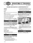
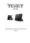
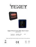
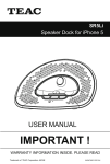
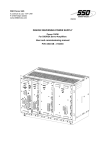
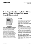
RS-15
USER’S GUIDE
UNIVERSAL MOTION AND PRESENCE SENSOR FOR AUTOMATIC DOORS
The RS-15 is a sensor developed to equip automatic inner doors in high-speed trains. The RS-15 has two functions: it detects motion to give an
opening signal and presence to prevent the door from closing on a stationary person within the presence detection zone. It has been designed to be
flush mounted.
TECHNICAL
SPECIFICATIONS
Technology
:
Focused active infrared
with microprocessor
Optical features
: 15 independent IR-spots
producing a squareshaped detection field
Mounting height (max)
: 2,5 m
Tilt angles
: 0° to 20° (step=5°)
Detection area (mounting height=2m; angle=20°)
: 1 m (W) x 1.2 m (D)
Spot dimension (typical)
: 130 mm (diameter)
Detection mode
: Motion and presence
Reaction time
: < 100ms
Supply voltage
: 12V to 30V AC ±10%
12V to 45V DC ±10%
Mains frequency
: 50 to 60 Hz
Power consumption
: < 3W (VA)
Output relay (free of potential change-over contact)
• Max. contact voltage
: 42V AC - 60V DC
• Max. contact current
: 1A (resistive)
• Max. switching power
: 30W (DC) / 60VA (AC)
Monitoring input (optocoupled, free of potential)
• Input voltage
: 10V - 24V DC
• Input current
: <10mA (at 24V)
Hold time
: 0.5s to 10s (adjustable)
LED
: Red and orange LED
Degree of protection
: IP41
Temperature range
: -25°C to +55°C
Connections
:
• Presence sensor side:
Integrated 7-pin connector on sensor side, unpluggable
Mounting
: Designed to be flush-mounted
Norms and conformity
:
• Presence sensor (without cable)
o EMC 2004/108/EEC
o EN 50155, DIN 5510-2:2009, NF F16-102/1992,
CEN/TS 45545-2:2009
• Presence sensor cable: DIN 5510-2:2009
Dimensions
Weight
Material
Color of housing
Length of cable
Manual adjustments
• Sensitivity (by push buttons)
• Shape of detection field (by push buttons)
• Tilt angle (mechanically)
Remote control adjustments
• Sensitivity
: 4 levels
• Hold time
: From 0.5s to 10s in 10 steps
• Shape of detection field
: Choice of 9 pre-programmed fields
• Max. presence time
: 20s to 25min in 10 steps
: 4-digit entry code
• Security
Wiring
DESCRIPTION
AND
WIRING
GREY
YELLOW
WHITE
GREEN
BROWN
Cable
LED
Pin
TILT ANGLE
ADJUSTMENT
Push button ‘B’
Push button ‘A’
Tilt angle adjustment
IR-Receiver
Relay (NC)
Relay (NO)
Relay (COM)
Power Supply
Power Supply
After power on, the sensor launches
a setup for a few seconds. It is
advisable to stay out of the field to
finish the setup successfully.
To adjust the tilt angle of the optical bloc use the small pin delivered with the product
(see figure above), insert it into the “tilt angle adjustment” slit (see figure above) and
adjust the angle from 0 to 20° (in steps of 5°).
At 2m high, with all the 15 spots “on”, the sensing fields are as follows:
Angle =
0°, Sensing field = 100cm (W) x 100cm (D).
Angle =
CONFIGURATION
WITH
PUSH BUTTONS
: 140mm(L) x 38mm(W) x
55mm(D)
: 0.1 kg
: PC
: Black smoked
: 1 m (total)
compliant with DIN5510
20°,
Sensing field = 100cm (W) x 120cm (D).
Without remote control, you can set two parameters using the push buttons : the “sensitivity” (from 1 to 4) and the “detection field” (from
1 to 9). See figure above for the location of the push buttons and the pin to activate the buttons.
To set the sensitivity:
1.
2.
3.
Press button A once to enter into an adjustment session for the parameter ‘sensitivity’. The RED LED now flashes. The number of flashes
indicates the current sensitivity setting.
Press button A again to increment the sensitivity. The RED LED indicates the current sensitivity setting. If you reach the value ‘4’ and press
button A again, the sensitivity will be ‘1’ (rolling value system).
If you reached the required sensitivity value, press button B to close the adjustment session.
To set the detection field:
1.
Press button B once to enter into an adjustment session for the parameter ‘detection field’. The ORANGE LED now flashes. The number of
flashes indicates the currently selected detection field (see page 2).
2.
Press button B again to go to the next detection field. The ORANGE LED indicates the currently selected field. If you reach the value ‘9’ and
press button B again, you will go back to detection field number ‘1’ (rolling value system).
3.
If you reached the required detection field, press button A to close the adjustment session.
If no button has been pressed within 1 minute, the adjustment session is automatically closed.
1/4
CONFIGURATION
WITH REMOTE
CONTROL
1.
INSERTION OF BATTERIES
•
•
•
2.
Open the battery compartment
Insert two AAA batteries as shown
Close the battery compartment
REMOTE CONTROL OPERATION
0-9 Number keys (1)
(10) Monitoring
(11) Detection field configuration
(12) Not used
Not used (2)
Plus
Unlock
Minus
Holdtime
Not used
(3)
(4)
(5)
(6)
(7)
(13)
(14)
(15)
(16)
Pulse frequency
Door control
Check Values
Lock
(17) Output configuration
(18) Maximum duration of presence detection
Not used (8)
(19) Set-up
Not used (9)
(20) Sensitivity (presence)
Remark: For optimum results point the remote control
vertically to the front of the sensor before pressing its
buttons. The sensor can be adjusted with its cover from a
distance up to 2m.
3. CONFIGURATION OF THE SENSOR
Every adjustment session using the infrared remote control must start with unlocking and end in locking. The table below lists the parameters able to be
adjusted by remote control and the operations required in order to adjust these parameters.
PARAMETERS
UNLOCK
OPERATIONS
Press the UNLOCK key (4).
Enter your 4-digit access code using NUMBER keys 0-9 (1).
LED SIGNAL
The red LED flashes quickly waiting for the access
code.
Press only the UNLOCK key (4) (no code required):
• during the first sensor adjustment;
• if the access code is reset to the "0000" value (factory setting);
• during the first minute after the power-on.
After entering the correct code or if no code is
required, the red LED flashes slowly to indicate that
the unlock was successful and the adjustment
session has begun.
UNLOCK with code
Note:
= Adjustment session ON
UNLOCK without code
LOCK
When all the parameters have been set, press the LOCK key (10).
If you wish to enter a new access code, use NUMBER keys 0-9 (1) to enter the
new 4-digit code within 1 minute.
If no access code is entered or if you want to keep the current access code,
press the LOCK key (16) once more.
If no remote control key is pressed within 1 minute, the adjustment session is
automatically locked.
The red LED stops flashing and returns to its normal
function.
LOCK with code change
LOCK without code or code change
2/4
Note :
All parameters or functions listed in the following tables are only accessible if the sensor is in adjustment session.
The red LED is then slowly flashing.
During an adjustment session each parameter may be checked or changed at any time in the following way :
PARAMETERS
CHECK VALUES
PLUS / MINUS
OPERATIONS
Press the key corresponding to the parameter to be checked and then press the CHECK VALUES key
Count the number of times the LED flashes, which corresponds to the value of the checked parameter. No LED flash corresponds to the
value 0. Repeat this operation to check the value of the other parameters if required.
Example : SENSITIVITY key– 4 flashes of the LED: the sensitivity is set to the value 4.
CHECK VALUES :
Press the key corresponding to the parameter to be modified (SENSITIVITY or HOLD TIME) and then press the PLUS key (2) or MINUS
key (4) to increase/reduce the value by 1 unit.
or
PLUS / MINUS :
Note about LED signal : The LED flashes quickly waiting for the value. Once this has been entered, it flashes slowly again.
PARAMETERS
SENSITIVITY
OPERATIONS
Press the SENSITIVITY key (20). Use the NUMBER keys 1-4 to enter the
required sensitivity (motion and safety)
HOLDTIME
SENSITIVITY:
Press the HOLD TIME key (6). Use the NUMBER keys 0-9 to enter the
required hold time (0.5s to 9 s)
DETECTION
FIELD
Press the DETECTION FIELD key (11). Use the NUMBER keys 1-9 to
select the desired detection field according to the table on the next page.
HOLD TIME:
DETECTION FIELD:
PULSE
FREQUENCY
Press the PULSE FREQUENCY key (13). Use the NUMBER keys 1-3 to
select the desired frequency:
1:
2:
3:
Low
Mid
High
Definitions - Advices
The hold time allows extended output activation time after
detection has stopped. It is recommended to use this
parameter instead of the operator’s one with the same
function (interferences with the sensor)
The detection pattern is made of 15 independent spots
organized in 3 ranges of 5 spots parallel to the door.
Each spot can be individually switched “on” or “off, set to
detect either motion or presence.
See next page “field detection”
The pulse frequency is used to avoid interferences
between sensors if their respective sensing fields are
overlapping. In that case choose different frequencies for
the sensors.
PULSE FREQUENCY:
OUTPUT
Press the OUTPUT CONFIGURATION key (17). Use the NUMBER keys 1CONFIGURATION 2 to select the required output configuration :
Active
Passive
Detection
No Detection
DOOR CONTROL
Press the DOOR CONTROL key (14). Use the NUMBER keys 1-3 to select
the required door operating mode:
1:
2:
3:
door automatic mode
door permanently open
door permanently closed
In “door permanently open” mode , the sensor is
continuously detecting. The red LED is continuously ON.
In “door permanently closed” mode, the sensor is in
standby. It detects nothing anymore and the LED is
continuously OFF.
DOOR CONTROL:
MAXIMUM
DURATION OF
PRESENCE
DETECTION
SETUP
0
Press the MAXIMUM DURATION OF PRESENCE DETECTION key (18).
Use the NUMBER keys 0-9 to select the required duration:
0:
1:
2:
3:
4:
20
1
2
3
5
seconds
minute
minutes
minutes
minutes
5:
6:
7:
8:
9:
7
10
15
20
25
minutes
minutes
minutes
minutes
minutes
The sensor will integrate the new environment and return
to no-detection state if detection has exceeded the
selected time.
MAXIMUM DURATION:
Press the SETUP key (19) followed by the NUMBER key 0 to launch a
setup of the sensor.
SETUP:
3/4
During an adjustment session, all parameters may be reset to their factory values as following:
PARAMETERS
DEFAULT
VALUES
9
OPERATIONS
Press the SETUP key (19), then press the NUMBER key 9. All the parameters are reset to the factory values (see next table).
DEFAULT VALUES :
Factory Values Table
Parameter
Sensitivity
Hold time
Detection field
Pulse frequency
Output configuration
Door control
Maximum duration of presence detection
DETECTION FIELDS
42.7644 / V2 – 08.2012
User’s guide for products with RM xxxxxx serial number
TROUBLESHOOTING
Values
1–4
0–9
1–9
1–3
1–2
1–3
0–9
Factory setting
3
0
1
2
1
1
0
The detection pattern is made of 15 independent spots organized in 3 ranges of 5 spots parallel to the door.
Each spot can be individually switched “on” or “off” in order to produce the most adapted detection field. Ex.: a deep and thin field, if
the RS-15 is facing the sitting passengers, or a wide and deep field, if the RS-15 is covering the platform.
Furthermore, each spot can be set to detect either “motion” (see grey spots bellow) or “presence” (see black spots bellow).
Given the many options, a pre-selection of 9 typical sensing fields is programmed into the sensor. These fields can be selected via
the remote control or the push buttons as explained hereafter.
SYMPTOMS
PROBABLE CAUSES
CORRECTIVE ACTION
The sensor will not power up.
Faulty power supply.
Door keeps opening and closing.
The sensor is disturbed by the door motion
because
1. the detection field is crossed by the door 1. Increase the tilt angle of the sensor.
leave(s).
2. of the vibrations caused by the door
2. Ensure the sensor is fastened correctly.
movement.
The sensing fields are overlapping.
Choose a different pulse frequency for the sensors (ex.
sensor 1: LOW, sensor 2: MID)
1. Batteries in remote control are dead or 1. Check to insure that the batteries are installed
installed improperly.
correctly, eventually replace batteries.
2. Remote control is badly pointed.
2. Point the remote control vertically to the sensor.
3. The sensor is doing a setup.
3. Cut and restore power supply and wait outside of the
detection field until the setup is finished (few seconds)
Improper code being entered.
Cut and restore power supply. No code is required to
unlock during the first minute after powering. Press on
“unlock”, then on “lock” and introduce a new access
code.
Sensor goes into a security mode after an Replace sensor.
internal sensor test failed.
Two sensors in close proximity are
disturbing each other.
The sensor does not respond to the
remote control.
The sensor does not unlock when the
access code is entered.
The red LED flashes quickly
(~2 flashes/sec).
Assure a correct power supply.
SENSORIO - a division of BEA SA | LIEGE Science Park | allée des Noisetiers, 5 - 4031 Angleur [BELGIUM]
T +32 4 361 65 89 | F +32 4 361 28 58 | [email protected] | www.sensorio.be
4/4