1
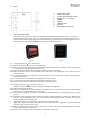
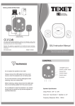
Digital Photo Frame With Alarm Clock
Model DPF-363
Transformer
Frame input
100-240V~ 50Hz,
500mA
5V
2.5W
Please read these instructions before use and retain for future reference
Table of Contents
1.
2.
3.
Safety…..………………………………..……………………………………………………………….3
Parts ………………………………..…………………………………………………………………..….4
Using the photo frame…..…..………………………………………………………………..4
4.
5.
6.
7.
8.
9.
3.1 Using the photo frame – with a memory card……..……………………...………4
3.2 Using the photo frame – with the internal memory...………..………...………4
3.3 Using the photo frame – changing how pictures are displayed……………5
Setting the clock…………………..……………………………………………………………….5
Setting and using the alarm..……………………………………………………………….6
Care and Maintainence………..……………………………………………………………….6
Troubleshooting guide..………..……………………………………………………………….6
Technical specifications….……..…………………………………………………………….6
Recycling electrical products.……………………………………………………………….6
We would like to thank you for your purchase of a Texet DPF-363.
The user manual should be thoroughly read to understand all functionality of the Texet DPF-363.
For further information on the TEXET range, please refer to www.texet.com
2
1.
•
•
•
•
•
•
•
•
•
•
•
•
•
•
SAFETY
FOR HOUSEHOLD AND INDOOR USE ONLY
PLACE THE APPLIANCE ON A FLAT, STABLE SURFACE WITH ADEQUATE VENTILATION AND AWAY FROM OTHER
SOURCES OF HEAT. MINIMUM DISTANCES AROUND THE APPLIANCE FOR ADEQUATE VENTILATION IS 5CM. DO NOT
COVER OR RESTRICT VENTILATION OPENINGS.
CHILDREN SHOULD BE SUPERVISED TO ENSURE THEY DO NOT PLAY WITH THE APPLIANCE, AND THE APPLIANCE
AND CABLE SHOULD BE KEPT COMPLETELY OUT OF REACH OF YOUNG CHILDREN.
THIS APPLIANCE IS NOT DESIGNED FOR USE BY CHILDREN, OR PERSONS WITH REDUCED PHYSICAL, SENSORY OR
MENTAL CAPABILITIES, AND SHOULD NOT BE USED BY SUCH PERSONS UNLESS THEY CAN DO SO SAFELY.
WHERE NECESSARY, SUCH PERSONS (OR ANYONE WITH LACK OF EXPERIENCE OR KNOWLEDGE) SHOULD FIRST
BE GIVEN SUPERVISION OR INSTRUCTION CONCERNING USE OF THE APPLIANCE BY A PERSON RESPONSIBLE FOR
THEIR SAFETY.
FULLY UNWIND THE CABLE BEFORE PLUGGING IN AND ENSURE THE CABLE IS POSITIONED AWAY FROM AREAS
WHERE IT IS LIKELY TO GET DAMAGED OR CAUSE A TRIP HAZARD.
THE OUTPUT CORD OF THIS MAINS ADAPTOR CANNOT BE REPLACED. IN THE EVENT OF DAMAGE TO THE CABLE,
JACK PLUG OR ADAPTOR, THE ENTIRE ADAPTOR UNIT SHOULD BE REPLACED.
CONNECTIONS MUST ONLY BE MADE VIA THE MAINS ADAPTOR SUPPLIED, NEVER CONNECT THE APPLIANCE
DIRECTLY TO THE 240V MAINS SUPPLY.
NEVER USE THE ADAPTER SUPPLIED WITH ANY OTHER APPLIANCE.
THE MAINS ADAPTOR WILL BECOME WARM IN USE; DO NOT COVER OR PLACE ON OR NEAR SURFACES THAT
COULD BE AFFECTED BY HEAT SUCH AS TABLE TOPS AND CARPETS.
DO NOT PULL ON CABLE TO DISCONNECT FROM MAINS SUPPLY.
KEEP APPLIANCE, CABLE, MAINS ADAPTOR PLUG DRY AND AWAY FROM AREAS WHERE IT IS LIKELY TO GET
SPLASHED. AVOID USING IN HOT, HUMID ENVIRONMENTS.
DO NOT PLACE ITEMS WITH NAKED FLAMES OR CONTAINERS WITH LIQUIDS ON THIS APPLIANCE.
SWITCH OFF AND UNPLUG WHEN NOT IN USE AND BEFORE CLEANING OR SERVICING THE APPLIANCE. SERVICING
OF THIS APPLIANCE MUST ONLY BE CARRIED OUT BY A QUALIFIED ELECTRICIAN.
ALWAYS ENSURE THE MAINS ADAPTOR PLUG IS READILY UNPLUGGABLE – DO NOT USE WITH ‘LOCKABLE’
SOCKETS OR PERMANENTLY WIRE TO MAINS.
The lightning flash with arrow-head
symbol,
within an equilateral
triangle, is intended to alert the user
to the presence of un-insulated
"dangerous voltage" within the
product's enclosure that may be of
sufficient magnitude to constitute a
risk of electric shock.
WARNING: TO REDUCE THE RISK OF ELECTRIC
SHOCK, DO NOT REMOVE COVER (OR BACK).
NO USER SERVICEABLE PARTS INSIDE, REFER
SERVICING TO QUALIFIED SERVICE
PERSONNEL.
3
The exclamation point within an
equilateral triangle is intended to
alert the user to presence of
important
operating
and
maintenance (servicing) instructions
in the literature accompanying the
appliance
2.
PARTS
1.
2.
3.
4.
5.
6.
7.
8.
9.
3.
Escape button (ESC)
Select button (SEL)
Function switch (ON/OFF / Light)
Navigation 3456buttons
Speaker
DC jack
USB slave port
Card slot
Mains adaptor (not shown)
USING THE PHOTO FRAME
This frame may be positioned so that either photographs are displayed (landscape format fig. 1) or the clock is
displayed (portrait format fig. 2). To use as a photograph frame, turn the frame to the landscape position and it
will automatically enter the photograph frame mode. When using as a photograph frame the photographs may be
either stored on a memory card (SD/MMC) or in the internal memory of the frame.
Fig. 1
Fig. 2
3.1 Using the photo frame – with a memory card
3.1.1 Peel off the protective film from the front of the screen.
3.1.2 Insert the memory card containing the photos into the frame and note that the orientation of the photo should be
set up on the PC before copying to the memory card.
3.1.3 Plug in the DC cable into the DC jack and plug the adaptor into the mains supply.
3.1.4 Slide the function switch to the ON position and a slide show of the photographs on the memory card will
automatically start.
3.1.5 To pause the slide show and display one picture constantly, press the SEL button. Press the button again to
restart the slide show.
3.1.6 To move forward to the next picture in the sequence, press the 4button.
3.1.7 To move back to the previous picture in the sequence, press the 3button.
3.1.8 To turn off the photo frame, slide the function switch to the OFF position.
3.2
3.2.1
3.2.2
3.2.3
3.2.4
•
•
3.2.5
3.2.6
Using the photo frame – with the internal memory
The frame provides 1.35MB of internal memory for the storage of photographs.
Switch off the photograph frame.
Connect the mini-B connector of the USB cable to the USB slave port on the frame and connect the remaining end
of the cable to an available USB port on the computer.
Ensure that the computer is switched on and slide the FUNCTION switch on the photograph frame to the ON
position.
The screen of the photograph frame will activate and three removable disks will be added to the ‘My Computer’
directory. The final removable disk is the internal memory of the photograph frame. Copy files to the internal
memory by either of the following routes.
‘Drag and drop’ files from the PC desktop / directory onto the removable disk.
‘Right click’ on the file to be copied and select ‘Copy’ from the shortcut menu. ‘Right click’ on the removable disk
and select ‘paste’ from the shortcut menu.
When all photographs have been copied or the internal memory is full, move the FUNCTION switch to the OFF
position and disconnect the USB cable.
Follow steps in “Using the photo frame” above for the operation of the frame.
4
3.3. Using the photo frame – changing how pictures are displayed.
3.3.1 Whilst the photos are being viewed, press and hold the ESC button and a drop down menu will be displayed on the
left hand side of the screen.
3.3.2 Use 5/ 6 buttons to move up and down the menu to highlight the desired function (see below). When the desired
function is highlighted, press the SEL button to confirm the selection and the available settings will be displayed.
3.3.3 Used 5/ 6 buttons to move up and down the menu to highlight the desired setting, press the SEL button to
confirm the selection and the desired setting will be displayed.
3.3.4 Press the ESC button to exit the menu or press and hold the button to exit this feature.
Note: Drop down menu only available at landscape format.
Function
Select card
Select mode
Language
Slide Speed
Available settings
Default
Internal memory or SD/MMC
Card
Photo or Clock
Various
English
Fast, normal or slow
Fast
Photo effect
Colour, Mono or Sepia
Colour
Photo mode
Auto fit, Full or Pan scan
Pan scan
Explanation
Sets the source of the photos to be displayed.
Selects the mode of operation.
Sets the language of the on screen display.
Sets the length of time that the photo will be displayed
before the frame displays the next picture.
Changes the colour of the photo displayed.
Select colour to display the photo in the original colour.
Select mono to display the picture black and white.
Select sepia to display the picture in sepia tone.
Changes the aspect of picture displayed.
Full - widens the picture from 4:3 to 16:9
Pan Scan - retains the picture at 4:3 but cuts the upper and
lower edge to fit the screen.
Auto - keeps the picture in the original ratio displays a black
margin to show the spare display area on the edges.
Select to reset all settings back to factory default settings
Select to exit the set up function
Reset setting
Exit
4.
4.1
4.2
4.3
4.4
4.5
4.6
4.7
4.8
•
•
SETTING THE CLOCK (only available at landscape format)
Whilst the photos are being viewed (landscape format), press and hold the ESC button and a drop down menu will
be displayed on the left hand side of the screen.
Use 5/6 buttons to highlight SELECT MODE and press the SEL button to select.
Use the 6 button to move down the menu and highlight CLOCK and press the SEL button to select this mode and
the clock will be displayed.
Press and hold the ESC button to display the clock set up menu.
Using the 5/6 buttons highlight SET TIME / DATE and press the SEL button to select.
Use the 5/6 to scroll through the feature until the correct date or time is displayed and use the 3/4 buttons to
move to the next field.
Press the SEL button to select and confirm the setting.
Press the ESC button to exit the menu or press and hold the button to exit the feature.
To display the time as a conventional clock face, turn the clock to the portrait position. To display the clock face
with the border illuminated, move the FUNCTION switch to the light bulb position.
To display a photograph with the time superimposed on the photograph. Follow steps 4.1 – 4.4 above to display
the clock set up menu. Using the 5/6 buttons to highlight SHOW TIME in the clock set up menu and press the
SEL button to select. Using the 5/6 buttons highlight ON and confirm using the SEL button. Press and hold the
ESC button to exit the set up feature and then turn the frame to the portrait position and then back to landscape
position. To remove the time display in the photograph mode, select OFF in the SHOW TIME menu.
5
5.
5.1
5.2
5.3
5.4
5.5
5.6
6.
SETTING AND USING THE ALARM (setup Menu only available at landscape mode)
Following steps 4.1 – 4.4 above, display the clock set up menu.
Use the 5/6 buttons to highlight ALARM SETTING and press the SEL button to select.
Use the 5/6 buttons to scroll through the alarm field until ENABLE is shown.
Use the 3/4 buttons to move to the next field and the 5/ 6 buttons to select the hour and minute.
When the correct alarm time is shown, press the SEL button to confirm the setting.
When the time on the clock is the same as the alarm time that has been set, the alarm will sound.
To silence the alarm, press the ESC button. The alarm will sound again the same time the following day unless the
alarm is disabled using the clock set up menu.
CARE AND MAINTENANCE
Wipe external surfaces with a soft cloth. If the frame is very dirty, unplug from the mains supply and use a damp
cloth soaked in a weak solution of washing up liquid and water. Wipe dry with a soft cloth and allow it to dry
thoroughly before reusing.
7.
TROUBLESHOOTING GUIDE
Observation
Potential cause / solution
The frame does not work
No start up screen
No photo being displayed.
8.
TECHNICAL SPECIFICATION
Rated voltage
Transformer output
Power consumption
100 - 240V~ 50Hz
5V
500mA
2.5W
Maximum picture size
Best resolution
Compatibility
File format
Card size
10 Megapixels
320 x 240 pixels
JPG and JPEG
4GB max (SD/MMC card)
PC system support
Operating conditions
Operating position
9.
Does the socket that is being used have power?
Is the frame switched on at the plug?
Is the adaptor correctly / fully connected?
Has the FUNCTION switch been moved to ON?
Has the memory card device been inserted?
Has the memory card been correctly inserted?
Have photos been saved on the memory card or internal memory?
Has correct photograph source (e.g. memory or card) been selected in the control menu?
Incompatible file format – is the photo saved in JPG or JPEG formats?
Windows 98, 2000 and XP
Temperature: -5°C to 40°C
Humidity 5% to 90%
Portrait or Landscape
RECYCLING ELECTRICAL PRODUCTS
You can now recycle your waste electrical goods and in doing so help the environment.
This symbol means an electrical product is designed for recycling when finished with.
Visit www.recycle-more.co.uk, click on “bank locator” and enter your postcode to find your nearest recycling site.
6