1
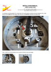
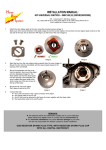
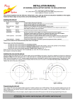
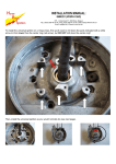
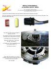
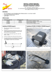
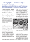
INSTALLATION MANUAL:
HPI UNIVERSAL IGNITION – ANALOGUE 3 CYLINDER 2 STROKE
(120° TRIPLE SPARK)
HPI – Kuilenstraat 97, 3960 Bree, Belgium
TEL: (0032) 089-46 74 39 | FAX: (0032) 089-47 33 28 | GSM: (0032) 0495-53 90 21
Email: [email protected] | Website: www.hpi.be
1.
Place piston one (cylinder one) at 2 to 4 mm before its most upper position. (OT) → see image 1
2.
Fit the rotor and the stator so that both markings are aligned.
► for right rotating → see image 2
► for left rotating → see image 3
Attention: - aligning has to be done on the first coil of the stator (see wiring)
- also mind the position of the HPI Logo on the rotor
Don’t tighten the screws yet.
3.
Make sure that the piston is in position and the markings are aligned.
If necessary, make adjustments by rotating the base plate of the stator.
4.
Tighten all the screws.
5.
Connect the CDI:
► the 3 pole connector from the first coil from the stator to a CDI-unit
► the orange cable from this CDI-unit to a HT-coil – the HT-coil must be connected to the frame
for mass (together with the black cable) – and this HT-coil to cylinder one
► connect the other coils from the stator accordingly
► the black/white cables from the three CDI’s to the on/off switch – use the y-branch
LOGO
Image 1
Image 2 (right rotating)
Image 3 (left rotating)
REMARKS:
► to gain performance, you can try to vary between the 2 to 4 mm setting.
INSTALLATION MANUAL:
HPI UNIVERSAL IGNITION – ANALOGUE 3 CYLINDER 2 STROKE
(120° TRIPLE SPARK)
HPI – Kuilenstraat 97, 3960 Bree, Belgium
TEL: (0032) 089-46 74 39 | FAX: (0032) 089-47 33 28 | GSM: (0032) 0495-53 90 21
Email: [email protected] | Website: www.hpi.be
THE FOLLOWING IS OPTIONAL
AND SHOULD ONLY BE DONE
BY PROFESSIONALS!!!
Doing this can be dangerous and harm you!
It is possible to embed the ignition into the housing, so the ignition doesn’t stick out as much. This may be done to
avoid the ignition scraping the ground while going through corners.
If you want the ignition embedded into the housing, ask a professional who knows how to work with his
machines, and how to do this safely. The maximum amount the ignition can be lowered is 11mm. Areas which
have to be removed are indicated with a red glow in the picture below. Be sure to remove the same length from
the bottom of the rotor cone adaptor. You will also have to fit new screw-thread in the three holes.