Transcript
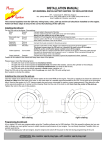
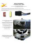
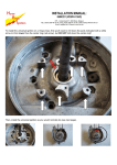
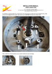
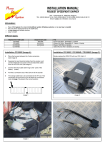
INSTALLATION MANUAL:
HPI UNIVERSAL IGNITION – 068K148 (XL250/XR250/XR500)
HPI – Kuilenstraat 97, 3960 Bree, Belgium
TEL: (0032) 089-46 74 39 | FAX: (0032) 089-47 33 28 | GSM: (0032) 0495-53 90 21
Email: [email protected] | Website: www.hpi.be
1.
Attach the rotor aligner plate to the rotor using the provided screws (image 1).
Make sure of the correct direction of the plate (image 2) and the correct rotation; the key from the rotor aligner plate must be on the
top side of the rotor, this is where the HPI logo is on the front of the rotor (image 3).
Image 1
Image 2
2.
Bend the key from the rotor aligner plate outwards from the rotor (image 4).
Mount the rotor onto the crankshaft, with the key properly placed in the
keyway of the crankshaft.
3.
Mount the baseplate onto the cover
from the ignition, then mount the stator
onto the baseplate (image 5). The
black plastic cap from the stator goes
into the opening of the baseplate. Be
sure to attach the black cable to the
stator using one of the two screws at
the top of the stator.
4.
Mount the HT-coil to the frame.
Don’t place it next to the CDI.
5.
Image 4
Connect the CDI:
► the 3 pole connector to the 3 pole connector of the stator
► the orange cable to the HT-coil
► the HT-coil must be attached to the frame for mass, together with the black cable
► the black/white cable to the on/off switch
Image 3
Image 5
REMARKS:
► the optional yellow and yellow/blue cables are for curve-selection,
these cables may never come in contact with the frame/mass !!!
► An incorrect installation can cause serious damage to your bike.
We are not responsible for defects caused by faulty installation.
USE RESISTOR SPARK PLUG TYPE, WITH RESISTOR SPARK PLUG CAP
WITH ALL DIGITAL IGNITIONS!!!