1
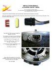
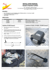
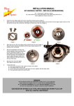
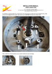
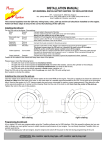
INSTALLATION MANUAL:
068K221 (VESPA CIAO)
HPI – Kuilenstraat 97, 3960 Bree, Belgium
TEL: (0032) 089-46 74 39 | FAX: (0032) 089-47 33 28 | GSM: (0032) 0495-53 90 21
Email: [email protected] | Website: www.hpi.be
To install the universal ignition on a Vespa Ciao, first you’ll need to mill down the parts indicated with a white
arrow to 2mm lower than the center ring (red arrow), but DO NOT mill down the center ring!!
Then, install the universal ignition as you would normally do (see next page).
INSTALLATION MANUAL:
068K221 (VESPA CIAO)
HPI – Kuilenstraat 97, 3960 Bree, Belgium
TEL: (0032) 089-46 74 39 | FAX: (0032) 089-47 33 28 | GSM: (0032) 0495-53 90 21
Email: [email protected] | Website: www.hpi.be
1.
Place the piston at 2 to 4 mm before its most upper position. (OT) → see image 1
2.
Fit the rotor and the stator so that both markings are aligned.
nd
► for right rotating: 2 large marking from the left → see image 2
nd
► for left rotating: 2 large marking from the right → see image 3
Attention: also mind the position of the HPI Logo on the rotor. Don’t tighten the screws yet.
3.
Make sure that the piston is in position and the markings are aligned.
If necessary, make adjustments by rotating the base plate of the stator.
4.
Tighten all the screws.
5.
Connections:
► the 3 pole connector of the stator to the 3 pole connector of the CDI
► the orange cable from the CDI to the HT-coil
► the HT-coil must be attached to the frame for mass, together with the black cable
► the black/white cable to the on/off switch
► the optional yellow and yellow/blue cables are for selecting a curve;
● cables loose
→ curve 1
● cables connected → curve 2
Image 1
Image 2 (right rotating)
Image 3 (left rotating)
REMARKS:
► to gain performance, you can try to vary between the 2 to 4 mm setting.
► HPI can deliver a switch to put between the optional yellow and yellow/blue cables,
making curve-selecting easy.
► the optional yellow and yellow/blue cables may never come in contact with the frame/mass !!!