Transcript
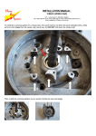
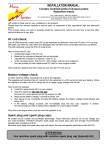
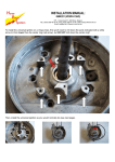
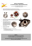
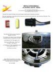
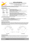
INSTALLATION MANUAL:
ELECTRONIC FUEL INJECTION SYSTEM: YAMAHA FZ-1
HPI – Kuilenstraat 97, 3960 Bree, Belgium
TEL: (0032) 089-46 74 39 | FAX: (0032) 089-47 33 28 | GSM: (0032) 0495-53 90 21
Email: [email protected] | Website: www.hpi.be
Disconnect the connector from the airpressure sensor. (img. 1)
Place the 2 connectors from the CDI-unit between these 2 connectors
(the connector from the airpressure sensor and the connector from
the disconnected cable) as an overpass.
There is some room next to the battery for the CDI-unit itself. (img. 2)
The image on the right shows the factory settings
for the potentiometers.
img.1
Starting RPM
Extra amount of fuel
LED
The fuel increasement
can only be changed if
the RPM is higher than
the starting RPM
=> LED lights up.
img. 2