1
INSTALLATION MANUAL:
HPI UNIVERSAL IGNITION – 068K292
HPI – Kuilenstraat 97, 3960 Bree, Belgium
TEL: (0032) 089-46 74 39 | FAX: (0032) 089-47 33 28 | GSM: (0032) 0495-53 90 21
Email: [email protected] | Website: www.hpi.be
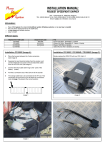
This part of the manual will explain how to get the stator cable through the opening in the carter.
First, use a screwdriver or any other tool with a sharp tip to remove the red cap from the 3 pole connector of the stator. Then
pull off the yellow rubber seal.
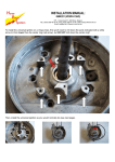
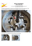
Now slide the 3 pole connector through the
opening in the carter.
The connector will only go through if positioned
exactly like shown in the pictures to the right.
Is it through yet? No? Just wiggle it a bit...
Maybe use a little muscle... Push! Push!
But wait... don't break it!
Is it through now? Well congratiolations, then!
You've reached LEVEL 2 !!!
Scroll down to continue...
Please follow the guidelines in our normal
installation manual on how to align and install the
innerrotor system on your engine.
(see next page)
INSTALLATION MANUAL:
HPI UNIVERSAL IGNITION – 068K292
HPI – Kuilenstraat 97, 3960 Bree, Belgium
TEL: (0032) 089-46 74 39 | FAX: (0032) 089-47 33 28 | GSM: (0032) 0495-53 90 21
Email: [email protected] | Website: www.hpi.be
1.
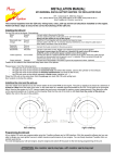
Place the piston at 2 to 4 mm before its most upper position. (OT) → see image 1
2.
Fit the rotor and the stator so that both markings are aligned.
nd
► for right rotating: 2 large marking from the left → see image 2
nd
► for left rotating: 2 large marking from the right → see image 3
Attention: also mind the position of the HPI Logo on the rotor. Don’t tighten the screws yet.
3.
Make sure that the piston is in position and the markings are aligned.
If necessary, make adjustments by rotating the base plate of the stator.
4.
Tighten all the screws.
5.
Connections:
► the 3 pole connector of the stator to the 3 pole connector of the CDI
► the orange cable from the CDI to the HT-coil
► the HT-coil must be attached to the frame for mass, together with the black cable
► the black/white cable to the on/off switch
► the optional yellow and yellow/blue cables are for selecting a curve;
● cables loose
→ curve 1
● cables connected → curve 2
Image 1
Image 2 (right rotating)
Image 3 (left rotating)
REMARKS:
► to gain performance, you can try to vary between the 2 to 4 mm setting.
► HPI can deliver a switch to put between the optional yellow and yellow/blue cables,
making curve-selecting easy.
► the optional yellow and yellow/blue cables may never come in contact with the frame/mass !!!