1
POWER SUPPLY
Voltage
Consumption
10 - 40 VDC or 19 - 28 VAC
Typical: 1.5 W, Max: 2.5 W
ENVIRONMENTAL CONDITIONS
Temperature
Humidity
Altitude
Storage Temperature
Protection
-10 - + 65°C
30 - 90% at 40°C non condensing
up 2000 m slm
-20 - +85°C
IP20
CONNECTIONS
Removable Terminals
Rear IDC10 Connector
4-way screw terminals (3.5 mm pitch): inputs/outputs.
CAN Interface and power supply (for DIN rail).
IDC10 Connector on the rear Digital Outputs (alternatively to terminals).
Stereophonic frontal jack
3.5 mm: RS232 (COM).
DIMENSIONS / BOX
Dimensions
Box
L: 100 mm, H: 112 mm, W: 35 mm
PBT, black
ISOLATIONS / STANDARS
Isolation Diagram
3-Point 1500 VAC Isolation
Standards
The module complies
following standards:
with
the
EN61000-6-4/2002-10 (electromagnetic emission,
industrial environment).
EN61000-6-2/2006-10 (electromagnetic immunity,
industrial environment).
EN61010-1/2001 (safety).
All circuits must be isolated from the other circuits under
dangerous voltage with double isolation. The power
supply transformer must comply with EN60742:
“Isolated transformers and safety transformers”.
Installation Rules
The module is designed to be installed in vertical
position on a DIN 46277 rail. In order to ensure optimum
performance and the longest working life, the module(s)
must be supplied adequate ventilation and no raceways
or other objects that obstruct the ventilation slots. Never
install modules above sources of heat; we recommend
installation in the lower part of the control panel.
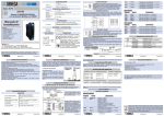
Inserting on the DIN rail
As it is illustrated in the figure:
1) Insert the rear IDC10 connector on a DIN rail free slot
MI001530-I/E
ENGLISH - 3/8