1
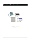
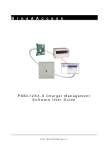
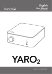
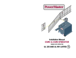
B r o a d A c c e s s
Installation Instructions
DAT64-CO Card
Description
The DAT64-CO card is a service card that supports co-directional 64 kbit/s
channels. The card receives data from the Local Exchange (LE) and uses it to
synchronize the CU to the LE.
Table 1. DAT64-CO Card – Features
Feature
Specification
Installed in
Max no. of cards per:
CAGE40-M
CAGE40-MIN
No. of lines
Interface
Line sensitivity
Bit rate
RU-subscriber maximum distance
CU & RU
15
4
8
4W G.703
3 dB
64 kbit/s
400-500 meters
Card Indicators
Card indicators are shown in Figure 1, and described from top to bottom in
Table 2.
DAT64CO
LI
ERR
ACT
RX1
RX2
RX3
RX4
RX5
RX6
RX7
RX8
Figure 1. DAT64-CO Card - Indicators
P/N 760-000154 Rev B
000154b.doc 03/02/2004 17:24
February 2004
Page 1
Card Indicators
Table 2. DAT64-CO Card – Indicator Descriptions
Indicator
Color
ERR (LD1)
Red LED
ACT (LD2)
Green LED
RX1 (LD3)
Yellow LED
RX2 (LD4)
Yellow LED
RX3 (LD5)
Yellow LED
RX4 (LD6)
Yellow LED
RX5 (LD7)
Yellow LED
RX6 (LD8)
Yellow LED
RX7 (LD9)
Yellow LED
RX8 (LD10) Yellow LED
Page 2
Status
ON
OFF
ON
OFF
ON
OFF
ON
OFF
ON
OFF
ON
OFF
ON
OFF
ON
OFF
ON
OFF
ON
OFF
Indication
At least one channel failed
Card is functioning normally
At least one channel is active
None of the channels are active
Channel 1 receives data properly
Channel 1 does not receive data
Channel 2 receives data properly
Channel 2 does not receive data
Channel 3 receives data properly
Channel 3 does not receive data
Channel 4 receives data properly
Channel 4 does not receive data
Channel 5 receives data properly
Channel 5 does not receive data
Channel 6 receives data properly
Channel 6 does not receive data
Channel 7 receives data properly
Channel 7 does not receive data
Channel 8 receives data properly
Channel 8 does not receive data
Note:
A self-test or forced-test will cause the LEDs on the card to flash until the test
procedure is completed. If a fault occurs, the red LED will remain ON.
Note:
During power up, all indicators remain on until card completes initialization.
February 2004
P/N 760-000154 Rev B
BroadAccess DAT64-CO Card - Installation Instructions
Configuration
Card jumpers and dipswitches are described in Table 3, and shown in Figure 2.
S1
J1
Figure 2. DAT64-CO Card - Jumpers
Table 3. Jumper and Dipswitches Settings
Item
Setting
J1
Function
Sets card operation to CU or RU:
J1
Card is set for operation in CU
CU
RU
J1
Card is set for operation in RU
CU
P/N 760-000154 Rev B
RU
February 2004
Page 3
Installation
Item
Setting
Function
S1
S1
In CU:
Down - Default
(1) (2) (3) (4) (5) (6) (7) (8)
Sub1
Sub8
In RU - forces permanent timeslot for selected
subscribers.
Note: Each subscriber may be selected individually.
S1
Up - permanent timeslots are allocated to selected
subscribers, even if no signal is received by RU.
(1) (2) (3) (4) (5) (6) (7) (8)
S1
Down - signal detection results in automatic timeslot
allocation.
(1) (2) (3) (4) (5) (6) (7) (8)
Note:
Numbers in parentheses do not appear on card, and indicate the subscriber
supported by this card.
Installation
Note:
System may remain powered while inserting card.
Caution: Modules can be damaged by electrostatic discharge (ESD). Before handling any
modules connect your wrist to an equipment ground using an approved anti-static
wrist strap. Ensure that all uninstalled modules are stored in anti-static packing
material. When working with modules, always place the module on an electrically
grounded approved anti-static mat.
Caution: Using excessive force when seating cards and modules into the backplane may
result in severe physical damage to the backplane pins or module connectors, and
if power is applied, may result in serious electrical damage to both the modules or
the backplane.
1. Place the grounded ESD wristband on your wrist.
2. Carefully remove card from package.
3. Set the jumpers/dipswitches on the card to the configuration required (see
“Configuration” above).
4. Slide the card into the cage as follows:
CAGE40-M - slots marked “1” to “15”.
CAGE40-MIN - slots marked “1” to “4”.
Page 4
February 2004
P/N 760-000154 Rev B
BroadAccess DAT64-CO Card - Installation Instructions
Caution: Seat the card into the backplane by sliding it through the card guide while holding
the ejector ears open. Fully seat the card by pressing the ejector ears in until they
lock into place. Do not force the cards into the backplane. If excessive resistance
is felt, remove the card and check for proper alignment in card guides or
obstructions.
5. If not already connected, connect cables to the cage as explained in “Cables”,
below.
Caution: If installing a new system, do not set the power cards main switch to ON until
system installation is complete, as described in the installation guide for your
specific cage.
Note:
For BroadAccess in Automatic Connection Mode:
Verify that a compatible card (see “Compatibility” in the Card Installation
Overview) is installed in the corresponding slot of the cage at the other end of the
link.
For BroadAccess in Manual Connection Mode:
Verify that a compatible card (see “Compatibility” in the Card Installation
Overview) is installed in a suitable slot of the cage at the other end of the link,
then use the management software provided with your system to perform line
provisioning accordingly. For further details, see the BroadAccess Configuration
Guide supplied in the Service Manual and in the ClearAccess+ User Guide.
6. After both the CU and RU are installed, powered up, and links are connected,
verify that indicator status is as described in “Card Indicators” above.
Otherwise, refer to “Alarms and Troubleshooting” in the BroadAccess
Maintenance Guide supplied in the Service Manual and in the ClearAccess+
User Guide.
Cables
Caution: Use caution when routing wires and cables. Avoid severe bending and routing
over sharp edges. Use grommet material when possible to avoid wear to cable
insulation.
Cables for this card are connected to cages using either of the following methods:
• Open cables - see Link, Service and Alarm Cables Connection Guide supplied
with your system’s Service Manual.
• Distribution blocks - see the installation instructions supplied with your
system’s Service Manual for your specific distribution block.
P/N 760-000154 Rev B
February 2004
Page 5