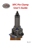
1
STC Series TRI-LOK Oval Power Clamps
User’s Guide
User’s Guide - BTM STC Model Tri-Lok Clamps
Table of Contents
1. The TRI-LOK Mechanism ............................................................. Page 1
2. How to Read the Label .......................................................................... 2
3. Mounting the clamp & Adjustable Dowel Kit ........................................ 2-3
4. Welding on the Clamp Arm .................................................................... 3
5. Removal and Remounting the Clamp Arm ............................................... 3
6. Arm Mounting Features ..........................................................................4
7. Air Supply ............................................................................................ 4
8. Cushion Adjustment & Fixed Orifices ..................................................... 4
9. How to Change the Rear Cushion/Degrees of Rotation ........................... 5
10. Lubrication ......................................................................................... 5
11. Proper Application Specifications ............................................ 6-7
12. Manual Unlock .................................................................................... 8
13. Buy Off Procedure .............................................................................. 8
14. Ordering spare parts ............................................................................ 8
15. Components ..................................................................................... 9-11
16. General specifications .......................................................................... 12
17. Warranty ............................................................................................13
082006
BTM CORPORATION • 300 DAVIS ROAD, MARYSVILLE, MI 48040 • Tel: 810-364-4567 Fax: 810-364-6178 www.btmcorp.com
User’s Guide - BTM STC Model Tri-Lok Clamps
Warning!
Always disconnect air and electrical supply lines before working on or around power clamps.
Introduction:
Thank you for selecting BTM’s patented STC model power clamp.
Our goal is to provide our customers with the best value in power clamps available. This User’s Guide is
intended to help you get the most value from the product; please read it through carefully. If you have
questions, call BTM at 810-364-4567. For service issues call our service pager at 810-340-3500 to
leave a message and we will promptly return your call.
1. The TRI-LOK Mechanism:
BTM’s patented TRI-LOK Mechanism can be
used as a clamp or a precision back up, and
eliminates “over-center” clamps.
Ways of using the
TRI-LOK mechanism
Toggle Clamp
Slide
A three point lock.
Mechanism does not
unlock if air pressure
Hub
is lost.
This surface repeats its position
with a high degree of accuracy
throughout the life of the unit.
When used as a toggle
clamp, the arm is
shimmed so that the
TRI-LOK mechanism
is not engaged. The
locking takes place
within the linkage.
Link
Precision Back up
Standard
Clamp
Arms
Toggle Clamp
Part Trap
082006
BTM CORPORATION • 300 DAVIS ROAD, MARYSVILLE, MI 48040 • Tel: 810-364-4567 Fax: 810-364-6178 www.btmcorp.com
1.
User’s Guide - BTM STC Model Tri-Lok Clamps
2. How to read the label
The label affixed to a BTM clamp contains the following information: (Ref. catalog 01-C.)
Serial Number : Used for tracing information.
Date : Date clamp was shipped from BTM.
Model Number : Indicates Clamp size &
mounting style, degree of arm rotation,
arm number, arm position and switch number.
Optional customer specific information:
Customers may supply additional information
for logistics purposes, such as; fixture
identification, program, unit, job,
Typical BTM clamp label
reference & purchase order numbers.
Contact information : Distributor name and telephone number.
Product Number : Identifies specifics of clamp: port size and type, mounting and degree of rotation.
3. How to mount the clamp:
Notice:
Blind dowel holes - (1) on each side. Do not drive through! Remove with dowel puller.
Blind threaded holes (2) each side.
Oval style STC (52, 62 & 82) clamps have (1) blind dowel hole on each side. Assembly personnel should
use care when inserting or removing dowel pins not to drive them through. Screw holes are also provided and require the following torque settings to be applied when mounting:
STC52= [M8 Screw] 39 Nm (29 ft-lbs)
STC62= [M10 Screw] 77 Nm (57 ft-lbs)
STC82= [M12 Screw] 135 Nm (100 ft-lbs)
Weldments or other mounting provided for the clamp
must be of sufficient rigidity to allow consistent
delivery of the force required by the application.
N.A.A.M.S.
Style
Mounting
2.
082006
BTM CORPORATION • 300 DAVIS ROAD, MARYSVILLE, MI 48040 • Tel: 810-364-4567 Fax: 810-364-6178 www.btmcorp.com
User’s Guide - BTM STC Model Tri-Lok Clamps
3.1 Optional Adjustable Dowel Mounting Kit:
BTM’s adjustable dowel kit allows precise adjustment of the clamp arms closed position after mounting,
by means of a lockable eccentric dowel which rotates the clamp (± 1/2o) relative to a
second “pivot”
dowel. The slot
Pivot Dowel
Threaded Tapered Plug (Expands Slot)
+1/2
insert is press- fit
Mounting Screws
Adjustment
Hex Head (Adjust Position)
in the clamp body
Press Fit Knurl
with the slot
Part
-1/2
Expansion Slot
Adjustment
oriented toward
Eccentric Pin
the pivot dowel.
Slot Insert
Adjustable Dowel Kit
Adjusting the
Adjustable Dowel Kit
eccentric pin
Clamp
rotates the clamp
Mounting Body
Blade
relative to the mount.
Pivot Dowel
Optional
Slot Insert: Align Slot
Toward pivot Dowel
Adjustable
Dowel Kit
o
o
4. Welding on Clamp Arms:
Remove the clamp arm before welding on it, or attach the ground cable directly to the arm so as not to
pass current through the bearings of the clamp mechanism.
5. Removal and Remounting of the Clamp Arm
Warning! Disconnect air pressure before attempting to remove the clamp arm.
BTM’s patented pin arm drive simplifies arm changes. To remove the clamp arm(s) remove the nut on the
center screw and carefully “unthread” the screw past the (2) internal “O” ring seals in the hub screw hole
(Figure A.). Do not push the screw through, as damage to the “O” rings may result. Once the center
screw is removed, the arm(s) may be tapped off with a mallet along with the assistance of a screwdriver
lifting the arm away from the clamp body to balance the force from the mallet. Should the pins(s) become
lodged in the arm, a through hole is provided to tap the pin from the arm with a drive punch and hammer.
Remounting the arm is done by first making sure the hub ring thread is tight, then simply use the witness
mark to properly locate the arm to the hub and tap the arm over the pins. Next, “thread” the center screw
through the “O” rings - Again, do not push the screw through, as damage to the “O” rings may result.
Finally, refit the nut and tighten the screw to the proper torque setting.
Figure. A
STC52= [M8 Screw] 23 Nm (17 ft-lbs)
STC62= [M10 Screw] 45 Nm (33 ft-lbs)
STC82= [M12 Screw] 79 Nm (58 ft-lbs)
Center Screw
O-Ring
O-Ring
Hub Ring
(1) Each Side
082006
3.
BTM CORPORATION • 300 DAVIS ROAD, MARYSVILLE, MI 48040 • Tel: 810-364-4567 Fax: 810-364-6178 www.btmcorp.com
User’s Guide - BTM STC Model Tri-Lok Clamps
6. Arm Mounting Features:
The BTM STC clamp features a pin drive hub, providing quick and easy positioning of the arm on either
side of the clamp. Simply tap the pins through to the desired side or install longer pins for dual arms.
The (8) pins allow for easy positioning of the arm at 450 increments. The machined surface of the arm
may be turned to face either way (“A” or “B” position).
“A” Position
“B” Position
7. Air Supply
BTM STC model power clamps are designed to operate on 5.8 bars (85psi) or less of clean, dry air. Air
delivery should be adequate to supply the following volume to each port to operate the clamp at a rate of
1 second open and 1 second closed:
STC 52 = 2.2 SCFMSTC62 = 4.5 SCFM STC82 = 9.2 SCFM
8. Cushion adjustment:
BTM STC model clamps are equipped with adjustable cushions to decelerate the arm mass and extend
the life of the clamp. Properly adjusted cushions only slightly reduce the speed of the clamp. Start by
closing the adjustment screw, then while cycling the clamp, gradually open the adjustment screw, until the
speed is minimally affected. Adjust to achieve the required cycle rate not exceeding the maximum rate of
1 second open and 1 second closed. Cycling the clamp faster than the maximum rate may result in
premature failure. Refer to charts on page 6.
8.1 Fixed Orifices:
STC model power clamps employ fixed orifices which are machined into the ports in both the end cap and
in the clamp body. These orifices are intended to protect the clamp from operating in excess of the recommended cycle rate relative to the mass of the arm . In some instances a second, smaller, orifice and/or flow
control valves may also be required. Three possible conditions exist in the application of STC clamps:
1. Normal: Speed and mass are compliant with the specification. No additional speed control
device is required, but flow control valves should be added to reduce impact.
2. Mass exceeds the charted specification: A smaller secondary orifice must be installed at the manifold.
Consult BTM’s sales department for proper sizing of the secondary orifice. Flow control valves should
also be added, in addition to the secondary orifice.
3. Mass complies with specification, but additional speed reduction is required for machine
timing or other purposes: Flow control valves must be added to further reduce the cycle rate.
4.
082006
BTM CORPORATION • 300 DAVIS ROAD, MARYSVILLE, MI 48040 • Tel: 810-364-4567 Fax: 810-364-6178 www.btmcorp.com
User’s Guide - BTM STC Model Tri-Lok Clamps
9. Changing the degree of rotation / rear cushion:
Before working on any clamp always disconnect the air pressure.
BTM STC model clamps are fitted with a removable rear cushion. This feature allows field changes of
the degree of clamp opening. Refer to the drawing on page 7. Proximity switch positions must be
changed accordingly (see 9.1 below).
STC 52
STC 62
STC 82
9
R EAR C U SHION ~ 30°
727007A
10
R EAR C U SHION ~ 45°
727001B
11
R EAR C U SHION ~ 60°
727001C
12
R EAR C U SHION ~ 75°
727001D
13
R EAR C U SHION ~ 90°
727001E
14
R EAR C U SHION ~ 105°
727001F
15
R EAR C U SHION ~ 120°
727001G
9
R EAR C U SHION ~ 30°
726007A
10
R EAR C U SHION ~ 45°
726001B
11
R EAR C U SHION ~ 60°
726001C
12
R EAR C U SHION ~ 75°
726001D
13
R EAR C U SHION ~ 90°
726001E
14
R EAR C U SHION ~ 100°
726001F
15
R EAR C U SHION ~ 120°
726001G
9
R EAR C U SHION ~ 30°
726510A
10
R EAR C U SHION ~ 45°
726501B
11
R EAR C U SHION ~ 60°
726501C
12
R EAR C U SHION ~ 75°
726501D
13
R EAR C U SHION ~ 90°
726501E
14 R EAR C U SHION ~ 105°
726501F
1. Make sure the clamp is in the open position.
15 R EAR C U SHION ~ 120°
726501G
2. Unscrew (4) S.H.C.S. to remove the End Cap.
3. Remove the S.H.C.S. holding the rear cushion and piston to the piston rod.
4. Pull out the rear cushion (Details 9 - 15)
5. Replace Rear Cushion with the appropriate detail to achieve required degree of opening. Use
Blue Loc-Tite on Cushion/Piston screws and apply a thin coat of grease to underside of screw head.
Tighten screw to appropriate torque (see below).
***NOTE: A cushion alignment tool must be used to prevent the piston from rotating when the screw is
tightened***
6. Reassemble End Cap and torque screws to appropriate torque (see below).
9.1 If the clamp is equipped with a status controlloer switch block:
7. Remove screws securing the switch block and remove the block.
8. Reposition the rear proximity sensor to the appropriate location and reassemble. Make sure
the wires are properly packed and the o-ring seal beneath the seal plate is in its groove as the block is
fitted. Then tighten the block to the body.
***NOTE: S2 Is always in the closed position.***
CLAMP
STC 52
STC 62
STC 82
CUSHION ALIGNMENT TOOL
727007AT
726007AT
726510AT
PISTON SCREW TORQUE
12 lb-ft (16 N-m)
24 lb-ft (32 N-m)
75 lb-ft (102 N-m)
END CAP SCREW TORQUE
12 lb-ft (16 N-m)
24 lb-ft (39 N-m)
50 lb-ft (68 N-m)
10. Lubrication
BTM STC model power clamps are lubricated for life at the factory. No other lubrication is necessary. In
line air lubrication is not required.
5.
082006
BTM CORPORATION • 300 DAVIS ROAD, MARYSVILLE, MI 48040 • Tel: 810-364-4567 Fax: 810-364-6178 www.btmcorp.com
User’s Guide - BTM STC Model Tri-Lok Clamps
11. Proper Application Specifications
11.1 Clamping Force
PIVOT
POINT
“A”
Force Output Formulas
STC52
NEWTONS =
Length
16,500 x LINE PRESSURE (BARS)
LENGTH (mm) FROM POINT “A” TO
CENTER LINE OF CLAMPING
CONTACT AREA ON CLAMP ARM
POUNDS =
10 x LINE PRESSURE (PSI)
LENGTH (in) FROM POINT “A” TO
CENTER LINE OF CLAMPING
CONTACT AREA ON CLAMP ARM
STC62
NEWTONS
=
46,500 x LINE PRESSURE (BARS)
LENGTH (mm) FROM POINT “A” TO
CENTER LINE OF CLAMPING
CONTACT AREA ON CLAMP ARM
POUNDS =
28.5 x LINE PRESSURE (PSI)
LENGTH (in) FROM POINT “A” TO
CENTER LINE OF CLAMPING
CONTACT AREA ON CLAMP ARM
STC82
NEWTONS =
92,000 x LINE PRESSURE (BARS)
LENGTH (mm) FROM POINT “A” TO
CENTER LINE OF CLAMPING
CONTACT AREA ON CLAMP ARM
POUNDS =
55 x LINE PRESSURE (PSI)
LENGTH (in) FROM POINT “A” TO
CENTER LINE OF CLAMPING
CONTACT AREA ON CLAMP ARM
11.2. Permissible Clamp Offset Distance
STC52 ~ SINGLE ARM: A = 37.5mm
DUAL ARM: A = 75mm
STC62 ~ SINGLE ARM: A = 75mm
DUAL ARM: A = 150mm
STC82 ~ SINGLE ARM: A = 150mm
DUAL ARM: A = 300mm
A
A
A
A
11.3. Arm Deflection Under Load
Force on arm at “X” distance from pivot resulting in 0.13mm [.005”] Maximum deflection.
STC52
"X" (mm) Force (N)
125
113
100
165
75
290
“X”
.013mm
6.
STC62
"X" (mm) Force (N)
250
156
225
200
200
245
175
289
150
378
125
489
100
734
STC82
"X" (mm) Force (N)
370
165
340
205
310
267
280
365
250
449
220
623
190
1005
160
1397
130
2073
100
3065
082006
BTM CORPORATION • 300 DAVIS ROAD, MARYSVILLE, MI 48040 • Tel: 810-364-4567 Fax: 810-364-6178 www.btmcorp.com
User’s Guide - BTM STC Model Tri-Lok Clamps
11.4. Maximum Allowable Weight on Clamp Arm Assembly
Refer to the charts below for model specific information regarding the recommended allowable weight on
the arm at given distances from the pivot. The distance from Pivot Point is the straight line distance from
the centerline of the clamp at the pivot point to the center of gravity of the clamp arm assembly. The
center of gravity is figured using the weight of the arm plus the total weight mounted on the arm. When
using dual arms, add the weight of the second arm to the total weight.
STC52
STC52
4.1
9.0
If application falls above
this curve, consider
using an STC62
Weight = Kg.
3.2
2.7
2.3
1.8
1.4
8.0
7.0
Weight = lbs
3.6
6.0
5.0
4.0
3.0
0.9
2.0
0.5
1.0
0.0
25
50
75
100
150 Distance From Pivot Point = mm.
0.0
127
STC62
11.0
Weight = Kg.
4.0
3.5
3.0
9.9
Weight = lbs
If application falls above
this curve, consider
using an STC82
4.5
2.5
8.8
6.6
5.5
25
0.0
50 75 100 127 150 175 200 225 250 275
Distance From Pivot Point = mm.
30.0
12.2
26.9
If application falls above
this curve, use (2)
clamps joined at the
clamp hub (Contact
BTM for details)
5.4
24.0
Weight = lbs
Weight = Kg.
6.8
21.0
17.9
15.0
If application falls above
this curve, use (2)
clamps joined at the
clamp hub (Contact
BTM for details)
11.9
4.1
9.0
2.7
6.0
1.4
150 175 200 225 250 280 300 330 350 380 400
430
Distance From Pivot Point = mm.
3.0
082006
1.0 2.0 3.0 4.0 5.0 6.0 7.0 8.0 9.0 10.0 11.0
Distance From Pivot Point = inches
STC82
13.6
8.1
If application falls above
this curve, consider
using an STC82
7.7
STC82
9.5
5.0
12.1
5.0
10.9
1.0
2.0
3.0
4.0
6.0 Distance From Pivot Point = inches
STC62
5.5
0.0
If application falls above
this curve, consider
using an STC62
6.0 7.0 8.0 9.0 10.0 11.0 12.0 13.0 14.0 15.0 16.0 17.0
Distance From Pivot Point = inches
7.
BTM CORPORATION • 300 DAVIS ROAD, MARYSVILLE, MI 48040 • Tel: 810-364-4567 Fax: 810-364-6178 www.btmcorp.com
User’s Guide - BTM STC Model Tri-Lok Clamps
Old Style
12. Manual Unlock - Release button:
Older model STC clamps are equipped with a release button which
allows the clamp to be manually opened when the air is off during
setup. A mallet may be required to tap the release button, and then
the arm to open the clamp.
Release
Button
12.1 Manual Unlock Access
STC Clamps are now being manufactured with an unlock access, rather than the release button. To
unlock the STC clamp with the air off, remove the front cover plug and and tap the linkage with a delrin
punch to unlock the mechanism. Replace the plug and tighten.
New Style
Remove Plug
Tap to unlock
13. Buy Off Procedure:
Stra
Dist1
ight
Str
ht
Line
aig
nc
e
ista
tanc
eD
Dis
Lin
e
Please contact BTM’s authorized
Distributors to certify proper application of
its STC-VP clamps. The figure depicted
to the right shows the typical information
that is required for application approval.
Certification will include an assessment
of the cycle rate and the weight of the
clamp arm assembly. Any
misapplications will be noted, and must
be corrected to recieve certification. The
warranty is dependant on certification of
the application.
Center of Gravity
of Clamp Arm
Assembly
Dist2
Dist3
Mass @ CG = ____
14. Ordering Spare Parts:
BTM STC Model Clamps are warranted for life of the tool which the clamp was originally sold for. Therefore, the unit is generally exchanged or repaired at the factory. If spare parts are required, contact BTM
sales at 810-364-4567.
8.
082006
BTM CORPORATION • 300 DAVIS ROAD, MARYSVILLE, MI 48040 • Tel: 810-364-4567 Fax: 810-364-6178 www.btmcorp.com
082006
9.
BTM CORPORATION • 300 DAVIS ROAD, MARYSVILLE, MI 48040 • Tel: 810-364-4567 Fax: 810-364-6178 www.btmcorp.com
BTM Assembly Numbers
733200A
733200B
733200C
733200D
733200E
733200F
733200G
733200J
733200K
733200L
733200M
733200N
733200P
733200R
733500A
733500B
733500C
733500D
733500E
733500F
733500G
733500J
733500K
733500L
733500M
733500N
733500P
733500R
745000A
745000B
745000C
745000D
745000E
745000F
745000G
745000J
745000K
745000L
745000M
745000N
745000P
745000R
For the series 740700 or 743800, reference the 745000 series.
30°
45°
60°
75°
90°
105°
120°
30°
45°
60°
75°
90°
105°
120°
Clamp
1/2-20
3/8-18
G1/4 Port
Opening SAE Port
NPTF Port
Clamp Specs
Single Arm
Dual Arm
1
2
3
4
5
6
7
8
9
10
11
12
13
14
15
16
17
1
1
1
1
1
1
1
8
1
1
1
1
1
1
2
2
1
BODY - 3/8 NPTF
PROX ACTUATOR
PROX MOUNTING SCREW
PISTON
PISTON ROD
SLIDE BLOCK
ARM MOUNT HUB
ARM MOUNT PIN - SINGLE
DRIVE ARM
END CAP - 3/8 NPTF
FRONT CUSHION
HUB RING
REAR CUSHION
LINK
LINK PIN
CUSHION ADJUSTMENT SCREW
UNLOCK PLUG COVER PLATE
DET. QTY. DESCRIPTION
740701A
733205A
733206A
727001A
727002A
727003A
727004A
727005A
727006A
740702A
call BTM
727012A
See p. 5
719207A
719209A
707422A
774100A
18
19
20
21
22
23
24
25
26
27
28
29
30
31
32
33
34
1
2
2
1
1
1
1
2
1
2
2
4
1
1
2
1
2
WASHER - .395 X .280 X .062
PARKER V6 CUSHION SEAL
POLYPAK SEAL
PARKER U-CUP PACKING
1/8 C/S SQB POLYSEAL
O-RING
O-RING
O-RING
O-RING
O-RING
URETHANE O-RING
M6 x 40 LG. S.H.C.S.
M6 x 50 LG. S.H.C.S.
M8 x 75 LG. S.H.C.S.
1/16 DIA. x 1/2 LG. ROLL PIN
M8 FLEX-LOC NUT THIN HT.
1/8 DIA. x 1/2 LG. ROLL PIN
BTM NO. DET. QTY. DESCRIPTION
019130
018092
019127
018085
019186
018083
018666
017531
004769
005418
018694
015764
014741
018368
001648
018367
016350
BTM NO.
STC52
Components
BTM Assembly Numbers
082006
BTM CORPORATION • 300 DAVIS ROAD, MARYSVILLE, MI 48040 • Tel: 810-364-4567 Fax: 810-364-6178 www.btmcorp.com
733300A
733300B
733300C
733300D
733300E
733300F
733300G
733300J
733300K
733300L
733300M
733300N
733300P
733300R
733600A
733600B
733600C
733600D
733600E
733600F
733600G
733600J
733600K
733600L
733600M
733600N
733600P
733600R
745100A
745100B
745100C
745100D
745100E
745100F
745100G
745100J
745100K
745100L
745100M
745100N
745100P
745100R
For the series 740800 or 743900, reference the 745100 series.
30°
45°
60°
75°
90°
100°
120°
30°
45°
60°
75°
90°
100°
120°
Clamp
1/2-20
3/8-18
G1/4 Port
Opening SAE Port
NPTF Port
Clamp Specs
Single Arm
Dual Arm
10.
1
2
3
4
5
6
7
8
9
10
11
12
13
14
15
1
1
1
1
1
1
1
1
1
1
1
1
1
2
2
BODY 3/8-18 NPTF
PROX ACTUATOR
PROX MOUNTING SCREW
PISTON
PISTON ROD
SLIDE BLOCK
ARM MOUNT HUB
DRIVE ARM
END CAP 3/8-18 NPTF
FRONT CUSHION
HUB RING
REAR CUSHION
LINK
LINK PIN
CUSHION ADJUSTMENT SCREW
DET. QTY. DESCRIPTION
740801A
733305A
733306A
726001A
726002A
726003A
726004A
726006A
740802A
call BTM
726011A
See p. 5
707429A
707407A
707422A
BTM NO.
16
17
18
19
20
21
22
23
24
25
26
27
28
29
30
1
1
2
2
1
1
1
1
2
1
2
2
2
4
1
UNLOCK PLUG COVER PLATE
WASHER - .500 X .377 X .06
PARKER V6 CUSHION SEAL
POLYPAK SEAL
PARKER U-CUP PACKING
1/8 C/S SQB POLYSEAL
O-RING
O-RING
O-RING
O-RING
URETHANE O-RING
METRIC O-RING
1/16 DIA. x 3/4 LG. ROLL PIN
M8 x 30 LG. S.H.C.S.
M8 x 50 LG. S.H.C.S.
DET. QTY. DESCRIPTION
772600A
019131
017538
019128
017536
019187
018083
018653
017531
001417
018695
020404
017537
016099
018512
BTM NO.
STC62
Components
BTM Assembly Numbers
733400A
733400B
733400C
733400D
733400E
733400F
733400G
733400J
733400K
733400L
733400M
733400N
733400P
733400R
733700A
733700B
733700C
733700D
733700E
733700F
733700G
733700J
733700K
733700L
733700M
733700N
733700P
733700R
745200A
745200B
745200C
745200D
745200E
745200F
745200G
745200J
745200K
745200L
745200M
745200N
745200P
745200R
For the series 740900 or 744000, reference the 745200 series.
30°
45°
60°
75°
90°
105°
120°
30°
45°
60°
75°
90°
105°
120°
Clamp
1/2-20
3/8-18
G1/4 Port
Opening SAE Port
NPTF Port
Clamp Specs
Single Arm
Dual Arm
082006
11.
BTM CORPORATION • 300 DAVIS ROAD, MARYSVILLE, MI 48040 • Tel: 810-364-4567 Fax: 810-364-6178 www.btmcorp.com
1
2
3
4
5
6
7
8
9
10
11
12
13
14
15
16
17
18
19
1
1
1
1
1
1
1
1
1
1
1
1
1
2
2
1
1
1
4
BODY - 3/8 NPTF
PROX ACTUATOR
PROX MOUNTING SCREW
PISTON
PISTON ROD
SLIDE BLOCK
ARM MOUNT HUB
DRIVE ARM
END CAP - 3/8 NPTF
FRONT CUSHION
HUB RING
REAR CUSHION
LINK
LINK PIN
CUSHION ADJUSTMENT SCREW
UNLOCK PLUG
FRONT COVER
FRONT COVER GASKET
M4 x 10 LG. S.H.C.S.
DET. QTY. DESCRIPTION
740901A
733406A
733407A
726501A
726502A
726503A
726505A
726509A
740902A
call BTM
726516A
See p. 5
726504A
726511A
707422A
772601A
741801A
741802A
018371
20
21
22
23
24
25
26
27
28
29
30
31
32
33
34
35
36
37
38
1
1
2
2
1
1
1
1
2
2
1
2
4
1
2
2
8
1
1
O-RING
WASHER - .700 X .564 X .072
PARKER V6 CUSHION SEAL
POLYPAK SEAL
PARKER U-CUP PACKING
POLYPAK SEAL
O-RING
O-RING
METRIC O-RING
O-RING
O-RING
URETHANE O-RING
M10 x 50 LG. S.H.C.S.
M12 x 75 LG. S.H.C.S.
3/32 DIA. x 1" LG. ROLL PIN
3/16 DIA. x 5/8 LG. ROLL PIN
STC82: ARM MOUNT PIN - SINGLE
M12 FLEX-LOC NUT THIN HT.
M12 x 110 LG. S.H.C.S.
BTM NO. DET. QTY. DESCRIPTION
001417
019132
018461
019129
018462
019430
018083
018459
019181
017531
003411
018696
017050
016250
018466
001645
726506A
018464
018465
BTM NO.
STC82
Components
Specification Compliance
®
BTM Tri-Lok Power Clamp
To GM Spec CC-002
16. General Specifications
¾
PATENTED TRILOK MECHANISM
¾
STANDARD N.A.A.M.S. MOUNTING
¾
SEALED MECHANISM - LUBRICATED FOR LIFE OF CLAMP
¾
BODY CONSTRUCTED FROM AIRCRAFT ALUMINUM - HARD COATED TO RC 70 FOR EXCELLENT WEAR
CHARACTERISTICS
¾
PIN ARM DRIVE FOR VERSATILE ARM POSITIONING & SIMPLIFIED ARM CHANGE
¾
ACCESS TO MANUALLY UNLOCK CLAMP LINKAGE
¾
EQUIVALENT BORE SIZES: 52.0mm [2.00"], 62.0mm [2.50"], & 82.0mm [3.25"] DIA.
¾
EASILY ADJUSTABLE ARM OPENING 30°, 45°, 60°, 75°, 90°, 105°, 120°
¾
MAXIMUM CYLINDER STROKE FOR 120° ARM OPENING = STC52 ~ 70.28mm [2.77"]
STC62 ~ 93.1mm [3.66"]
STC82 ~ 118.8mm [4.68"]
¾
APPROX. WEIGHT(WITHOUT ARMS) : STC52 ~ 3.8 kg [8.4 lbs], STC62 ~ 5.7 kg [12.6 lbs.], STC82 ~ 13.6 kg [30.0 lbs]
¾
OPERATING PRESSURE: 2.75 TO 7 BARS [40 TO 100 PSI] (LUBRICATED OR NON-LUBRICATED COMPRESSED AIR)
~ USE FLOW CONTROLS TO REDUCE IMPACT
¾
HOLDING TORQUE:
STC52 ~ 290 N-m [214 ft-lbs]
WITHOUT AIR
STC62 ~ 450 N-m [330 ft-lbs]
STC82 ~745 N-m [550 ft-lbs]
¾
CLAMPING TORQUE:
STC52 ~ 89.5 N-m [66 ft-lbs @ 5.5 BARS [80 PSI]
AT HUB
STC62 ~ 257.6 N-m [190 ft-lbs @ 5.5 BARS [80 PSI]
STC82 ~ 496.2 N-m [366 ft-lbs @ 5.5 BARS [80 PSI]
¾
CLAMP INTERCHANGABILITY TOLERANCE: ±0°15' (CLAMP TO CLAMP)
¾
ARM REPEATABILITY IN CLOSED POSITION: ±0° 3'
FIGURE 1
FIGURE 2
CLAMP INTERCHANGEABILITY TOLERANCE
ARM POSITION CYCLIC REPEATABILITY
Dowels
±.001
±.001
Mounting Surface
(Body) to Mounting
Surface (Arm
Mounting) Within
±.005
Pivot Point
±.001
±.001
90O ± 0O 3’
6” Ref.
90O ± 0O 15’
±.005 Ref.
@ 6” From
Pivot Point
12.
082006
BTM CORPORATION • 300 DAVIS ROAD, MARYSVILLE, MI 48040 • Tel: 810-364-4567 Fax: 810-364-6178 www.btmcorp.com
STC Series TRI-LOK Oval Power Clamps
User’s Guide
Warranty:
BTM Corporation warranties its STC Clamps against defects in material and workmanship for for the life of the tool which the clamp was originally sold for.
This warranty is limited to replacing or repairing at BTM’s option, F.O.B. BTM’s factory, any part
found by BTM to be defective in materials and/or workmanship. Any application of a BTM product
outside the intended use of the product shall not be warranted by BTM Corporation. Furthermore,
BTM will not be liable for any expenses incurred for repairs or replacement made outside BTM’s
facilities without written consent (or damages arising out of such replacements or repairs). Under no
circumstances will BTM be held responsible for any consequential damages.
The warranty is limited to the repair or replacement of the defective part(s) and does not include
installation.
This warranty is the only warranty extended by the seller in connection with any sale made hereunder
and is in lieu of all other warranties, express, implied or statutory including warranties of merchantability and fitness for purpose.
13.
BTM CORPORATION • 300 DAVIS ROAD, MARYSVILLE, MI 48040 • Tel: 810-364-4567 Fax: 810-364-6178 www.btmcorp.com