1
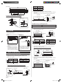
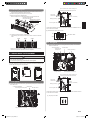
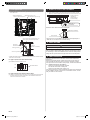
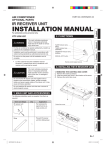
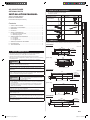
Q’ty
Name and shape
Screw-B
Operating manual
Cable clip
1
Contents
Grille
Cable tie (Medium)
1
2. MAIN UNIT & ACCESSORIES......................................................... 1
3. DIMENSION ..................................................................................... 1
4. LOCATION ....................................................................................... 2
5. INSTALLATION METHOD................................................................ 2
5.1. Mounting the bracket frame ...................................................... 2
5.2. Mounting the grille .................................................................... 3
6. WIRING-INSIDE THE EQUIPMENT ................................................ 3
6.1. For type-A ................................................................................. 3
6.2. For type-B ................................................................................. 3
6.3. For type-C1/C2 ......................................................................... 4
7. WIRING-OUTSIDE THE EQUIPMENT ............................................ 4
2
3
Bracket frame
Bushing
1
Screw-A
1
10 mm
16
3. DIMENSION
8. FIELD SETTING .............................................................................. 4
Diagrams showing connection between bracket frame and grille are given below.
9. TEST OPERATION .......................................................................... 4
UTD-GQSD-W
[Top view]
Unit : mm
645
4 × Ø3.2
burring hole
Bushing (*1)
P200 × 3=600
29
683
555
23
249
Firmly install the grille. Or else, it may fall and cause an injury.
Bushing (*1)
Русский
883
86
312
353
UTD-GQSF-W
[Top view]
Türkçe
Don’t install the unit where it will be exposed to direct sunlight. Or else, it may
cause a change in color.
180
116
130
775
Do not move the up-down louvers manually. It may cause a malfunction.
1045
P200 × 5 = 1000
6 × Ø3.2
burring hole
Bushing (*1)
29
74
Use an appropriate grille that is compatible with the indoor unit. Refer to Design
& Technical manual for further details. If not used with the correct combination, it
may cause condensation.
2 × Ø5 hole
463
[Front view]
Perform heat insulation and field setting according the manual. Not installing as
per the instructions may cause condensation.
When the installation area is exposed to direct sunlight, take measures to block
the light such as covering the grille surface with a sheet. Or else, it may cause a
change in color.
5 × Ø3.2
burring hole
P200 × 4= 800
Do not install the unit in the following areas
• In the upper part of the vicinity of room entrance. It may cause condensation
on the outlet port.
• Near a wall surface. It may cause condensation on the wall during cooling.
• Area filled with mineral oil or containing a large amount of splashed oil or
steam, such as a kitchen.
Unit : mm
74
CAUTION
This mark indicates procedures which, if improperly
performed, might possibly result in personal harm to the
user, or damage to property.
216
845
29
Never touch electrical components immediately after the power supply has been
turned off. Electrical shock may occur. After turning off the power, always wait 5
minutes or more before touching electrical components.
UTD-GQSE-W
[Top view]
EλληvIkά
130
180
Install at a location that can sufficiently withstand the weight. If the strength is
inadequate, grille may fall and cause an injury.
Do not turn ON the power until all work has been completed. Turning ON the
power before the work is completed can cause serious accidents such as electric
shock or fire.
Italiano
[Front view]
This mark indicates procedures which, if improperly
performed, might lead to the death or serious injury of the
user.
2 × Ø5 hole
263
116
WARNING
74
1. SAFETY PRECAUTIONS
• Be sure to read this manual thoroughly before installation.
• The warnings and precautions indicated in this manual contain important
information pertaining to your safety. Be sure to observe them.
• Hand this manual, together with the operating manual to the customer.
Request the customer to keep them on hand for future use, such as for relocating
or repairing the unit.
English
6
Deutsch
1
For authorized service personnel only.
1. SAFETY PRECAUTIONS ................................................................ 1
Q’ty
10 mm
Français
Name and shape
Installation manual
(This manual)
Español
AUTO LOUVER GRILLE
PART NO. 9380267027
• The following installation parts are supplied.
Use them as required.
Português
INSTALLATION MANUAL
2. MAIN UNIT & ACCESSORIES
中國語
AIR CONDITIONER
OPTIONAL PARTS
663
2 × Ø5 hole
En-1
9380267027-01_IM_EN.indd 1
10/8/2013 1:59:32 PM
[Front view]
1083
116
130
180
995
Screw-A
12 places
GQSE
14 places
GQSF
16 places
(4) Insulate the bracket frame. (Insulation material: Field supply)
Create a slit in the insulation material on the wiring hole so that the cable can
pass through.
18
453
Model
GQSD
412
*Be sure to insulate so as not to expose the metal sheet of bracket frame.
[Top view]
UTD-GQSD-W, UTD-GQSE-W, UTD-GQSF-W
[Side view]
Bracket frame
2
2 × Ø3.2
burring hole
29
Indoor unit
*1) Detailed drawing of bushing
84
74
Slit width:
20 to 25 mm
Ø5 hole
Wall
Ø35
42
Do not leave any clearance
B: When using a rectangular duct
42
Ø2
In 3
of ner D
the ia
bu me
sh ter
ing (ID
)
Ø23
35
78
148
Bushing
9
[Side view]
Insulation material
CAUTION
Grille
Securely fasten the bracket frame on a stable foundation. Or else, it may cause an injury.
(1) Bore a hole in the wall. The rectangular duct dimensions follow figure below.
Create a wiring hole in the rectangular duct (right side) if the wiring hole is
covered with the rectangular duct.
[Top view]
Select the installation location that meets the following requirement and that is
approved by the customer.
• Cold and warm air should reach the entire room.
Indoor unit
PROHIBITED
Rectangular
duct
42 mm
*2
GOOD
C: Inner dimensions of the
rectangular duct
[Side view]
35 mm
4. LOCATION
Wiring hole
Ø 25 to 35 mm
D
C
148 to 152 mm
Installation
height *1
Wall
Install grille
facing the floor *3
D ≤ 1000 mm
Install grille
facing the ceiling *3
floor
*1) Refer to Design & Technical manual
for air velocity distribution and air
temperature distribution during
heating.
*2) If the distance from the ceiling is
not adequate, it may cause mildew
stains on the wall or the ceiling.
(Ensure to fix at least 150 mm away
from any surface of the equipment.)
*3) Do not install as the figure shown
right. In addition, do not install
multiple grilles on a single indoor
unit. The warm air or cold air may
not run smoothly in the entire
room.
Model
C (mm)
GQSD
647 to 651
GQSE
847 to 851
GQSF
1047 to 1051
(2) Mount the bracket frame on the rectangular duct. Fasten it with screw-A
(Accessories) or Rivet (Field supply).
Mount so that the wiring hole is on the right side of the frame.
Rectangular duct
[Top view]
Indoor unit
Wall
5. INSTALLATION METHOD
Bracket
frame
No clearance
5.1. Mounting the bracket frame
Rectangular duct
Wall
A: When directly connecting to the indoor unit
(1) Bore a hole in the wall
(3) Insulate the rectangular duct. (Insulation material: Field supply)
Create a slit in the insulation material on the wiring hole so that the cable can
pass through.
*Be sure to insulate so as not to expose the metal sheet of bracket frame.
148 to 152 mm
C
Model
C (mm)
GQSD
647 to 651
[Top view]
GQSE
847 to 851
GQSF
1047 to 1051
Indoor unit
[Side view]
Insulation material
(2) Mount the bracket frame on the wall.
Mount so that the wiring hole is on the right side of the frame.
Slit width:
20 to 25 mm
(3) Fasten the bracket frame and the indoor unit with screw-A (Accessories).
Indoor Unit
[Top view]
Wall
Bracket frame
No clearance
Wall
35 mm
Indoor unit
Do not leave any clearance
Screw-A
Screw-A
Screw-A
Wall
[Side view]
42 mm
Wiring hole
En-2
9380267027-01_IM_EN.indd 2
10/8/2013 1:59:34 PM
Open a knockout hole. Insert the bushing. And
pass the louver grille cable through this hole.
5.2. Mounting the grille
(1) Pass the cable through the wiring hole. Insert the cable so that the wiring
length from the grille to wiring hole is 150 mm.
(2) Seal the wiring hole with putty from the inner side.
(3) Mount the grille on the bracket frame.
Mount so that there is no clearance between the grille and the wall.
Seal the wiring hole with
putty from inner side.
* Bracket frame is actually
mounted on the wall.
Wiring hole
Opening this
knockout hole
Cable tie
(Medium / Accessories)
Bushing (Accessory)
Auto louver grille cable
15
0
m
m
Cable
(2) Set SW2 of DIP switch “SET4” to ON.
(4) Fasten the screw-B (6 places, Accessories).
After fastening the 2 screw-B in the center, fasten 4 screw-B on both the
sides.
STEP2
STEP1
* Collect all the cables if there are any other cables. Refer to the installation manual
of the indoor unit for details.
ON
DIP switch “SET4”
OFF
STEP2
SW SW SW SW
2
3
1
4
6.2. For type-B
(1) Connect the cable to the auto louver grille terminal (CN11) of the controller
PCB of the indoor unit.
• Wiring arrangement
* Fasten the screw with the protective tape affixed on the up-down louvers.
Remove the protective tape after the work is completed.
Auto louver grille
terminal(CN11)
Controller PCB
Bushing (Accessory)
6. WIRING-INSIDE THE EQUIPMENT
CAUTION
• To protect the cable insulation after opening a knockout hole, remove any
burrs from the edge of the hole.
• Do not bind the power supply cable and other cables together.
Controller PCB located inside the electric equipment box differs according to the
model. Set according to the controller PCB.
Type-A
Type-B
Type-C1/C2
Jumper wire JM2
Cable tie (Medium / Accessories)
Open a knockout hole. Insert the bushing. And
pass the louver grille cable through this hole.
Opening this
knockout hole
6.1. For type-A
(1) Connect the cable to the auto louver grille terminal (CN12) of the controller PCB
of the indoor unit.
• Wiring arrangement
Cable tie
(Medium / Accessories)
Bushing (Accessory)
Switches PCB
Auto louver grille terminal (CN12)
DIP switch “SET4”
Auto louver grille cable
* Collect all the cables if there are any other cables. Refer to the installation manual
of the indoor unit for details.
(2) Cut jumper wire JM2
Jumper wires
JM3
JM1
JM2
Cable tie (Medium / Accessories)
Controller PCB
En-3
9380267027-01_IM_EN.indd 3
10/8/2013 1:59:36 PM
7. WIRING-OUTSIDE THE EQUIPMENT
6.3. For type-C1/C2
(1) Connect the cable to the auto louver grille terminal (CN12) of the controller PCB
of the indoor unit.
• Wiring arrangement
(1) Firmly fasten the cable in line with the side surface of the indoor unit with
cable clip. Fasten the cable clip jointly with the screw of the control box cover.
Switches PCB (Type-C1 only)
Auto louver grille terminal (CN12)
Sagging of the wire:
under 20 mm
Wires should not
touch the ceiling
DIP switch “SET4” (Type-C1 only)
Cable clips × 2
(Accessories)
Bundle the extra cables as shown in the diagram.
Cable tie (Accessories)
Controller PCB
60 to 100 mm
Clamp
Open a knockout hole. Insert the bushing. And
pass the louver grille cable through this hole.
*If the indoor unit is not installed in the wall, cover the exposed part of
cable with a 1 mm thick or more insulation tubing.
8. FIELD SETTING
Opening this
knockout hole
Cable tie
(Medium / Accessories)
CAUTION
Set the static pressure settings correctly. If not set correctly, it may cause a condensation.
Bushing (Accessory)
Perform static pressure setting according to the static pressure on the inlet
side. For details of static pressure setting, refer to the corresponding contents
of “Field setting” in indoor unit installation manual. Perform the static pressure
settings with the up-down louvers and right-left louvers in horizontal position.
Auto louver grille cable
* Collect all the cables if there are any other cables. Refer to the installation manual
of the indoor unit for details.
For Type-C1 (Indoor units with switches PCB)
(2) Set SW2 of DIP switch “SET4” to ON.
ON
DIP switch “SET4”
OFF
SW SW SW SW
2
3
1
4
For Type-C2 (Indoor units without switches PCB)
9. TEST OPERATION
Adjust the right-left louvers so that warm air and cold air reaches the
entire room.
Refer to the operating manual, operate the up-down louvers with a remote controller and check the up-down louvers is operating normally.
If the up-down louvers is unable to work properly, confirm the instructions
in "6. WIRING-INSIDE THE EQUIPMENT".
• Have the connectors been tightly inserted?
• Has the DIP switch been correctly set?
• Have the jumper wires been correctly cut?
If the indoor unit does not work, troubleshoot according to the instructions
on the installation manual of indoor units. If it still does not work, consult
with your dealer or service center.
(2) If there is no switches PCB in the indoor unit, set it with wired remote controller
or wireless remote controller. Please refer to the installation manual of the
indoor unit and the remote controller.
En-4
9380267027-01_IM_EN.indd 4
10/8/2013 1:59:40 PM