1
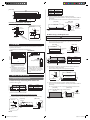
Open a knockout hole. Insert the bushing. And
pass the louver grille cable through this hole.
5.2. Mounting the grille
(1) Pass the cable through the wiring hole. Insert the cable so that the wiring
length from the grille to wiring hole is 150 mm.
(2) Seal the wiring hole with putty from the inner side.
(3) Mount the grille on the bracket frame.
Mount so that there is no clearance between the grille and the wall.
Seal the wiring hole with
putty from inner side.
* Bracket frame is actually
mounted on the wall.
Wiring hole
Opening this
knockout hole
Cable tie
(Medium / Accessories)
Bushing (Accessory)
Auto louver grille cable
15
0
m
m
Cable
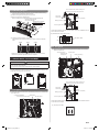
(2) Set SW2 of DIP switch “SET4” to ON.
(4) Fasten the screw-B (6 places, Accessories).
After fastening the 2 screw-B in the center, fasten 4 screw-B on both the
sides.
STEP2
STEP1
* Collect all the cables if there are any other cables. Refer to the installation manual
of the indoor unit for details.
ON
DIP switch “SET4”
OFF
STEP2
SW SW SW SW
2
3
1
4
6.2. For type-B
(1) Connect the cable to the auto louver grille terminal (CN11) of the controller
PCB of the indoor unit.
• Wiring arrangement
* Fasten the screw with the protective tape affixed on the up-down louvers.
Remove the protective tape after the work is completed.
Auto louver grille
terminal(CN11)
Controller PCB
Bushing (Accessory)
6. WIRING-INSIDE THE EQUIPMENT
CAUTION
• To protect the cable insulation after opening a knockout hole, remove any
burrs from the edge of the hole.
• Do not bind the power supply cable and other cables together.
Controller PCB located inside the electric equipment box differs according to the
model. Set according to the controller PCB.
Type-A
Type-B
Type-C1/C2
Jumper wire JM2
Cable tie (Medium / Accessories)
Open a knockout hole. Insert the bushing. And
pass the louver grille cable through this hole.
Opening this
knockout hole
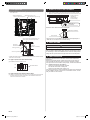
6.1. For type-A
(1) Connect the cable to the auto louver grille terminal (CN12) of the controller PCB
of the indoor unit.
• Wiring arrangement
Cable tie
(Medium / Accessories)
Bushing (Accessory)
Switches PCB
Auto louver grille terminal (CN12)
DIP switch “SET4”
Auto louver grille cable
* Collect all the cables if there are any other cables. Refer to the installation manual
of the indoor unit for details.
(2) Cut jumper wire JM2
Jumper wires
JM3
JM1
JM2
Cable tie (Medium / Accessories)
Controller PCB
En-3
9380267027-01_IM_EN.indd 3
10/8/2013 1:59:36 PM