1
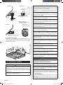
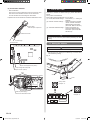
7.3.1. Button name and function
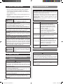
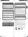
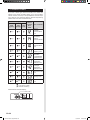
Table B
Custom code
A (Factory setting)
B
DIP SW
SET 3 SW1
DIP SW
SET 3 SW2
C
D
OFF
ON
OFF
ON
OFF
OFF
ON
ON
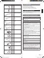
7.3. Function setting
• FUNCTION SETTING can be performed with the wired or
wireless remote controller.
(The remote controller is optional equipment)
• Refer to the wired or wireless remote controller manual for detailed setting information. (Set IU AD, REF AD SW to 0)
• Refer to “7.1. Setting the address” for indoor unit address and
refrigerant circuit address settings.
• Turn the power of the indoor unit ON before starting the setting.
* Turning on the power indoor units initializes EEV, so make
sure the piping air tight test and vacuuming have been conducted before turning on the power.
* Also check again to make sure no wiring mistakes were
made before turning on the power.
FILTER indicator
lamp (Red)
TIMER indicator
lamp (Orange)
OPERATION indicator
lamp (Green)
MANUAL AUTO
button
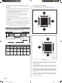
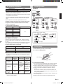
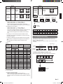
Function details
Function
Filter
indicator
interval
Function
number
11
Filter
indicator
action
13
Ceiling
airflow
20
Vertical
airflow
direction
23
Cool air
temperature
trigger
30
Hot air
temperature
trigger
Auto
restart
External
control
31
40
Setting
number
00
Default
01
Longer
02
Shorter
00
Enable
Disable
Display only
on central
02
remote controller
Default
Details
○
Adjust the filter cleaning
interval notification. If the notification is too early, change to
setting 01. If the notification is
too late, change to setting 02.
○
01
00
Default
01
High
Ceiling
00
Default
01
Raise
00
Default
01
Adjust (1)
02
Adjust (2)
00
Default
01
Adjust (1)
02
Adjust (2)
03
Adjust (3)
00
Enable
01
Disable
00
Start/Stop
01
Emergency
stop
○
○
Adjust the cool air trigger
temperature. To lower the
trigger temperature, use setting 01. To raise the trigger
temperature, use setting 02.
○
Adjust the hot air trigger
temperature. To lower the trigger
temperature by 6 degrees C, use
setting 01. To lower the trigger
temperature by 4 degrees C, use
setting 02. To raise the trigger
temperature, use setting 03.
○
○
46
00
47
All
Display only on
01 central remote
controller
Regulate the airflow according to the needs of the
installation location. When
set to 01, the air flow will be
stronger.
Adjust the vertical airflow
direction. All airflow direction
louvers are adjusted together.
(Cassette type only)
○
02 Forced stop
Error
report
target
Enable or disable the filter
indicator. Setting 02 is for use
with a central remote controller.
○
Enable or disable automatic
system restart after a power
outage.
Allow an external controller to
start or stop the system, or to
perform an emergency stop.
* If an emergency stop is
performed from an external
controller, all refrigerant
systems will be disabled.
* If forced stop is set, indoor
unit stops by the input to
the external input terminals,
and Start/Stop by a remote
controller is restricted.
Change the target for reporting
errors. Errors can either be
reported in all locations, or
only on the wired remote.
(Optional)
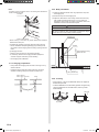
7.3.2. Checking the function settings
• Press and hold the “MANUAL AUTO” button on the indoor unit
for 3 seconds to check the function settings. It is necessary
to disconnect the power in order to return to normal operation
mode.
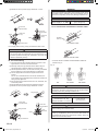
(1) Indoor unit and refrigerant address indication
Indication pattern
Indication pattern
Indoor unit
Refrigerant address
address
Indicator name
OPERATION
indicator lamp
(Green)
TIMER indicator
lamp (Orange)
FILTER indicator
lamp (Red)
ON
Flash
(1.0s ON/1.0s OFF)
Address: tens place
(0.5s ON/0.5s OFF)
Address: ones place
(0.5s ON/0.5s OFF)
• Indoor unit address example
(Example) ADDRESS : 24
1 cycle 12 sec
OPERATION ON
indicator lamp
(Green)
OFF
ON
TIMER
indicator lamp
(Orange)
OFF
ON
FILTER
indicator lamp
OFF
(Red)
ON
0.5s 0.5s 0.5s 0.5s
10 sec
0.5s 0.5s 0.5s 0.5s 0.5s 0.5s 0.5s 0.5s
8 sec
En-18
9371022208-02_IM_EN.indd 18
8/31/2012 2:42:34 PM