1
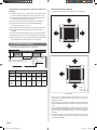
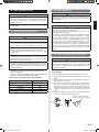
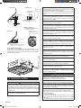
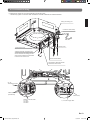
• Refrigerant piping and drain piping positions.
3.3. Installing the unit
10 mm
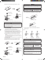
• If the job is done with the panel frame only, there is a risk that
the unit will come loose. Please take care.
3.3.1. Position the ceiling hole and hanging bolts
950 mm (Panel frame)
20 - 45 mm
20 - 45 mm
200 mm
• Distribution ducts and fresh air inlet positions.
Distribution duct connecting port
Fresh air inlet position
Distribution duct connecting port
50 mm
130 mm
278 mm
Distribution duct connecting port
20 - 45 mm
130 mm
840 mm (Body frame)
80 mm
130 mm
699 mm (Hanging bolt pitch)
795 mm (Hanging bolt pitch)
950 mm (Panel frame)
860 - 910 mm (Ceiling opening)
840 mm (Body frame)
860 - 910 mm (Ceiling opening)
20 - 45 mm
358 mm
200 mm
• Ceiling opening and hanging bolt pitch.
Drain pipe
(Connect the attached
drain hose)
140 mm
(1) Positions of the ceiling opening, hanging bolt pitch, piping
and ducts. (unit: mm)
Drain pipe
Refrigerant pipe
Distribution duct connecting port
A
B
185mm
352mm
Ø 70mm
Cut out
185mm
250mm
40 mm
10 mm
B
256
298
10 x Ø 2.5 hole
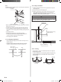
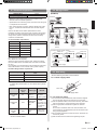
Detailed diagram of distribution duct connecting port (4 sides)
Ø 88mm
Burling hole pitch
A
246
288
100mm
83mm
Cut out
90mm
140 - 145 mm
50 - 100 mm
100mm
83mm
Model
18/24L
30/36/45/54L
60 mm
Gas pipe
Liquid pipe
180 mm
• Install the air conditioner in a location which can withstand a
load do at least 5 times the weight of the main unit and which
will not amplify sound or vibration. If the installation location
is not strong enough, the indoor unit may fall and cause
injuries.
80 mm
WARNING
4 x Ø 2.5 hole
Fresh air inlet position
En-5
9371022208-02_IM_EN.indd 5
8/31/2012 2:42:10 PM