1
Input device 2 Input device 1
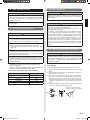
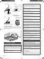
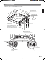
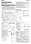
(2) Please fix the Connection cable with cable Clamp. And then
install the Wire Cover with screws.
(c)
Bind securely
Load
resistance
*a
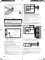
DC power supply *1
12 - 24V
+
P.C.B
+
-
1
2 CN6
3
*b
Load
resistance
*a
connected unit
CAUTION
• Do not bundle the remote controller cable, or wire the remote
controller cable in parallel, with the indoor unit connection
wire (to the outdoor unit) and the power supply cable. It may
cause erroneous operation.
1
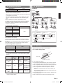
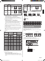
When connected to voltage terminals of multiple indoor units with
a connected unit, be sure to make a branch outside the indoor
unit using a pull box, etc. as shown on below example.
6.5. External input and external output
(Optional parts)
Input device 1
Load
resistance
Input device 2
Controller PCB
DC power
supply 12-24V
Load
resistance
P.C.B
CN6
P.C.B
CN6
Indoor unit
(3) Install control box cover.
*1 Make the power supply DC12 to 24V. Select a power supply
capacity with an ample surplus for the connected load.
Do not impress a voltage exceeding 24V across pins 1-2, and 1-3.
*a The allowable current is DC5~10mA. (Recommended:
DC5mA)
Provide a load resistance such that the current becomes
DC10mA or less.
Select very low current use contacts (usable at DC12V,
DC1mA or less).
*b The polarity is [+] for pin 1 and [-] for pin 2 and 3.
Connect correctly.
Indoor unit
Detail (c)
P.C.B
CN6
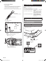
Input No Voltage terminal (CN17)
Input Voltage terminal (CN6)
Output terminal (CN16)
• No voltage terminal ([CN17])
When a power supply is unnecessary at the input device you
want to connect, use the no voltage terminal ([CN17]).
(1) External input terminals
• Indoor unit can be Start/Stop or Emergency stop, Forced stop
by using indoor unit PCB CN6 or CN17.
Wiring methods and specifications
• A twisted pair cable (22AWG) should be used. Maximum length
of cable is 150 m.
* Use an external input and output cable with appropriate
external dimension, depending on the number of cables to be
installed.
• The wire connection should be separate from the power cable
line.
• Input selection
Use either one of these types of terminal according to the
application. (Both types of terminals cannot be used simultaneously.)
• Voltage terminal ([CN6])
When a power supply must be provided at the input device you
want to connect, use the voltage terminal ([CN6]).
Indoor unit
connected unit
P.C.B
1
*c
*c
Ch 1
Ch 2
2 CN17
GND
3
*d
connected unit
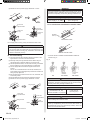
*c Select very low current use contacts (usable at DC12V,
DC1mA or less).
*d The wiring is different from voltage terminals. Be sufficiently
careful when wiring.
When connected to no voltage terminals of multiple indoor units
with a connected unit, insulate each indoor unit with relay, etc. as
shown on below example.
When connected to multiple indoor units directly, it will cause
breakdown.
En-14
9371022208-02_IM_EN.indd 14
8/31/2012 2:42:31 PM