1
E N G L I S H
The body and various parts, if unusable, should be dismantled and divided
according to their material type (for example, copper, aluminium, plastic,
etc.) and must be sent to collection centres.
4.4.3. Electric/electronic waste disposal.
In keeping “Implementation of Directives 2002/95/CE, 2002/96/CE and
2003/108/CE” on the reduction of the use of hazardous substances in
electric and electronic material as well as waste disposal. The barred bin
symbol on the equipment or packaging indicates that the product must
be separated from other waste at the end of its working life. Therefore,
the user must take equipment to electronic and electro-technical waste collection
centres at the end of its working life or return it to the dealer when purchasing similar
new equipment, on a one to one basis. Suitable collection of decommissioned
equipment for recycling, processing and environmentally compatible disposal
contributes in avoiding possible negative effects on the environment and health and
promote the reuse and/or recycling of device materials. Illicit product disposal by the
user may be punishable by current national laws.
4.5. Hydraulic connections.
4.5.1. Warnings.
The heat pump hydraulic connections must be performed by specialised technicians
and in keeping with current national system regulations.
During hydraulic connections, avoid using free flames near or within the heat pump.
The following retail components are recommended for hydraulic connections:
•
Cut-off valves upstream and downstream from the heat pump to facilitate
maintenance and/or heat pump bypass from the pool hydraulic system.
•
Hydraulic circuit charge and drain valve for the heat pump.
•
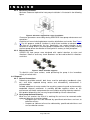
Hydraulic circuit bypass valve, see Figure 6.
•
Mechanical filter upstream from the heat pump, usually a sand filter.
•
Non-return valve, installed between the pool and the heat pump output fitting,
to prevent water reflux.
Tubes that have the same diameter of the heat pump inlet and outlet are
recommended for upstream and downstream heat pump connections.
During periods of heat pump disuse, for example, during the winter, drain water
from the heat pump circuit and heat pump.
Chemical dosing devices, when applicable, must be installed downstream from the
heat pump and non-return valve. This prevent chemically saturated water reflux
which could damage the heat pump.
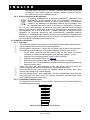
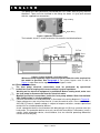
4.5.2. Installation hydraulic layout.
The hydraulic circuit where the heat pump is installed must be created observing
the following general layout.
o
Swimming pool
Pump
Filter
Heat pump
Non-return valve
Chemical regulator
Swimming pool
Figure 4: General hydraulic circuit layout.
Nome file: 7500016 - ISTR.INSTALL. HEAT PUMP VERS. EN.doc
Page 10-di/of 40
Rev. 3 del/of 11/06/2009