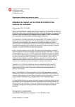
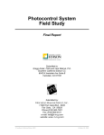
1
 Flow Center User Manual
With plug-in for M3-series
61A7E15 About this Manual
This manual describes how to install and use Flow Center with the M plug-in for the Eletta
M3-series Flow Meter.
•
The latest version of this manual is available for download on our website
www.eletta.com.
•
On our website you will also find other information such as leaflets, newsletters,
application reports and software download.
Proprietary Rights
This manual contains confidential technical data, including trade secrets and proprietary
information that are the property of Eletta Flow AB, Sweden.
Any changes or alterations to downloaded or printed Eletta original documentation such as
manuals, drawings, leaflets, newsletters etc, are not permitted without a written permission
from Eletta Flow AB, Sweden.
These data are only disclosed to you under permission of limited use within your company.
Use for manufacturing or processing is not permitted.
Any other use of data and information is strictly prohibited without prior written permission
from Eletta Flow AB, Sweden.
61A7E15 1. General Information
Flow Center is a software developed by Eletta Flow to communicate with the Eletta M3series Flow Meter. The M3-series Flow Meters is used to measure and control flows of
liquids and gases in pipes.
Flow Center is currently only available for use with Microsoft Windows.
The communication between the software and the Flow Meter is bi-directional. This means
that the software reads existing data and parameters from the Flow Meter. It also allows you
to re-configure the flow meter using the communication cable for M-series.
The communication cable for M-series is a USB cable with a RS 485 converter and is
available to purchase from Eletta Flow.
2. Technical specification for communication cable
•
•
•
•
•
•
61A7E15 Supply via USB for one connected final consumer (U-Out = 11,8 VDC / I-Out
max=40 mA)
Measuring channel: voltage input 0...12 VDC
Visual status and configuration display (LED)
Galvanic isolation
Total length: 1,7 m
Driver package included with package
3. Installation
Flow Center software, M plug-in and driver K-114B for the communication cable are
available for download from http://www.eletta.se/en/downloads/softwaredrivers/. Check for
the latest versions online.
1) Open the "Setup flow_center X.X", choose installer language and follow the setup
wizard to install. Available languages are Swedish and English. Run the setup as
administrator. If you don´t have the necessary privileges, please contact your IT
support before installing the software.
2) Flow Center does not work without the required plug-in. If you are to communicate
with the M3 flow meter, open the "Setup Flow Center M plugin - X.X". Choose
installer language and follow the setup wizard to install. Run the setup as
administrator. If you don´t have the necessary privileges, please contact your IT
support before installing the software.
3) Install the driver K-114B for the communication cable. The driver for the RS485USB communication cable is available for download online at Eletta server
http://www.eletta.se/en/downloads/softwaredrivers/.
Run the setup as administrator. If you don´t have the necessary privileges, please
contact your IT support before installing the software.
Refer to the manual in the package for troubleshooting and system requirements for
the USB-RS485 converter.
4) Connect the communication cable to any USB port on your computer and the M3
unit.
5) Run Flow Center X.X
61A7E15 4. Overview
General Functions
File/
Action: Change language (Program must be restarted)
Action: Quit program
M/
Action: Access log function settings. Also accessible using
Action: Add a new M to Flow Center Also accessible using
Help/
Action: Info about the software and version
Action: Info about plug in
61A7E15 button.
button.
New functions will first appear when a device is connected with Flow Center.
Setup
Action: Configure settings for the device.
Add new device
Action: Connects a new device to Flow Center.
Remove device communication
Action: Disconnects a device.
Change MODBUS ID
Action: Allows you to set a specific identification No for each devise. The MODBUS
interaction is not yet fully developed and should be used with pre-caution.
Change mode
Action: Change the mode you use the M3 device. 4 different modes are supported with the
M3 unit.
1.
2.
3.
4.
DP (Differential pressure measurement)
Flow (Incompressible flow)
Gas flow (ABS) Volumetric flow mode.
Gas flow (NORM) "Mass flow" mode (Flow value must be density multiplied realtime wrt current temperature and absolute pressure. Not supported by software)
Load transmitter settings from file
Action: Load previously saved device settings.
Save transmitter settings to file
Action: Allows you to save device settings.
61A7E15 5. Connect a device
Connect the Flow Meter to your PC with the communication cable for M3-series and open
Flow Center.
Add new device. The following input box will appear:
Click on UPDATE to find all connected/occupied USB ports. Choose the port where the
device is connected. Click on OK and the device will be uploaded for communication.
The AUTODETECT can be unchecked to search and communicate with a specific device
with a certain Modbus ID. The MODBUS interaction is not yet fully developed and should be
used with pre-caution.
Once the device is connected it shows up with a green online icon followed by the units
unique S/N. When clicking on the connected device you enter the read view which
consists of 5 different sub pages where you can oversee Overview (Displaying all
measurements in one page), Flow rate, Differential pressure, Temperature and Static
pressures. Note that the scaling is dependent on the settings saved on the device and
measurements will be performed immediately as the unit is connected.
61A7E15 On the left bottom side of the screen is the device information frame.
Here you can see
•
•
•
•
•
•
•
•
•
•
S/N: Serial number
Class: Transmitter class
Version: Software version written to the sensor card of the device (Keller software)
Qmax: Maximum flow saved to the unit
DP max: Differential pressure over orifice to match Qmax
P range: Static pressure range min..max
T range: Temperature range min..max
Address: ModBus ID
Mode: What mode the device is set to measure and report values for
Port: What COM port the device is connected to
6. Measurement Sub-pages
6.1 Overview
The overview is a collection of all vital parameters as measured by the device. Here you can
check in real-time:
61A7E15 1.
2.
3.
4.
5.
6.
7.
8.
9.
Flow (Not active in DP mode)
DP
Analog out
Min measurable flow (As determined by the dynamic turn down)
P1 Pressure upstream
P2 Pressure downstream
Turndown (As determined by the ratio SQRT(100% FLOW DP/DPmin device) )
TP Coeffs (Only active for Gas flow mode)
Temperature (Measured on the sensor card of the device and not in the media)
Scaling and units can be altered real-time and will be automatically displayed with new
settings on the screen. Note that these settings are only changed graphically and not saved to
the unit. If the device is disconnected and re-connected, the units and scaling values will be
changed to match settings saved on the device.
6.2 Flow rate
The flow rate sub-page is a real-time graphically on-going presentation of the flow in time.
The time frame is changeable. There is also the option of showing volume totalizer or not.
The output analogue signal is also shown on the page.
6.3 Differential pressure
The differential pressure sub-page is similar to flow rate sub-page. The output analogue
signal is also shown on the page. The time frame is changeable and so also the units. Note
that these settings are only changed graphically and not saved to the unit. If the device is
disconnected and re-connected, the units and scaling values will be changed to match settings
saved on the device.
61A7E15 6.4 Temperature
The temperature sub-page is similar to flow rate sub-page. The output analogue signal is also
shown on the page. The time frame is changeable and so also the units. Note that these
settings are only changed graphically and not saved to the unit. If the device is disconnected
and re-connected, the units and scaling values will be changed to match settings saved on the
device.
6.5 Static pressures
The static pressure sub-page is similar to the other sub-pages. Here you can show both
pressure measurements or choose to uncheck one of them. The output analogue signal is also
shown on the page. The time frame is changeable and so also the units. Note that these
settings are only changed graphically and not saved to the unit. If the device is disconnected
and re-connected, the units and scaling values will be changed to match settings saved on the
device.
61A7E15 7. Change settings on a device
Push the
Setup button to unlock the settings on the device. The settings loaded will
automatically be the settings on the device.
Do not change DP, Q (flow) or Calc. coefficients. They are parameters connected to the bore
size of the orifice plate. Changes will cause errors in output.
Q range is set to 100 l/min when delivered from Eletta factory regardless of which flow range
the orifice plate is specified for. This means that when you first connect your Flow Meter to
Flow Center, the flow rate reading will most likely appear incorrect unless you have a 100
l/min specified orifice plate installed. This does not mean that the mA output signal is
incorrect. The mA output signal is determined by that the installed orifice plate and the set
DP range corresponds. To get a correct reading in Flow Center you need to set Q range to the
maximum range of your installed orifice plate.
61A7E15 7.1 Measurement range
Here you can change the max flow and corresponding DP range. Note that these values are
related to the orifice in the pipe section and should not be changed without ordering a new
orifice made according to new settings. The Max pressure is the maximum allowed static
pressure. This is defined by the pressure transmitter installed in the Flow Meter. Eletta
provides three different transmitters with static pressure limitations of 10, 25 and 50 bar.
There is also the option of custom tagging the unit to a specific name.
7.1.1 Q range
States the maximum flow for your specific orifice. The value that is set as Q range will
always correspond to 100% of the set DP range.
7.1.2 DP range
Determines the differential pressure span from where the transmitter calculates the flow. The
orifice plate installed must be calculated so that 100% flow corresponds to 100% DP that is
set in the DP range field. All orifice plates for the M3-series Flow Meter are engraved with
the max DP range that corresponds to max flow rate.
Normally the value in the DP range field is not to be changed. Do not change this field
without checking the orifice plate versus DP range.
7.1.3 Drop-out
This field shows when the Flow Meter stops to measure. When the differential pressure goes
below the set value, the output signal will go down to 4 mA and the indicated flow will go
down to zero. This is to prevent the Flow Meter showing erratic flow at zero condition. The
default value is set just below 10% of the max DP range. If you see an unstable flow when
you have a non-flow condition, you can raise this value to avoid seeing it. For example,
vibrations can cause these erratic small values, therefore you might want to cut them off.
61A7E15 7.2 Pressure settings
7.2.1 Pressure setting DP/FLOW mode
For incompressible flow and DP mode there is the option of setting the transmitters to gauge
pressure. Zero bar (g) will remove the small pressure differences in-between the two
transmitters and then set the DP to zero bar (g) as a start value to gauge pressure
measurement. The calibration will take some time before stabilizing the values. Click Save
when you are satisfied with the calibration. This is done at the factory at the on-site
atmospheric condition and will not be representative of the pressure conditions of all
customer installations. Always check the pressure settings before starting the measurement. If
necessary, zero bar(g), the unit.
Original setting (fabrication settings) values can be retrieved by returning to default values.
This is mainly used for troubleshooting and should not be used as a run setting for this mode.
7.2.2 Pressure setting GAS mode
Gauge pressure setting for gas flow is not possible. Here you can either reset the transmitters
to default values or re-calibrate and save the current atmospheric pressure condition as
measured with the unit. Setting the P1 and P2 to atmospheric pressure condition will do the
same as the zero bar (g) action for DP/flow. It will measure the absolute pressures and
remove small differences in-between the transmitters. The calibration will take some time
before stabilizing the values. Click Save when you are satisfied with the calibration. This is
done at the factory at the on-site atmospheric condition and will not be representative of the
pressure conditions of all customer installations. Always check the pressure settings before
starting the measurement. If necessary, set P1 and P2 to atmospheric pressure.
Original setting (fabrication settings) values can be retrieved by returning to default values.
This is mainly used for troubleshooting and should not be used as a setting for this mode.
61A7E15 7.3 Calculation coefficients for GAS mode
Gas flow modes have an extra setting to define the standard (ordinary or stationary customer
operation settings) line pressure and temperature. This is information the device must know
in order to have a P/T compensation that will work satisfactory.
Do not change these values. They are connected to the orifice bore. Changes will disrupt
measurement.
7.4 Output signal
The user can re-scale the 4-20 mA output signal. The output can be set inversely also, letting
the 0% flow be 20 mA and 100% flow be 4 mA. You can change the low-pass filter value if
there is a need to make the device more sensitive to display changes or to make the unit more
slow to detect changes in differential pressure.
8. Impact of settings
8.1 Low pass filter setting
The low pass filter is a damping that will be applied to the calculation of the output signal. If
the filter value is set to 0 there will be no damping of the signal and will thus make the device
more sensitive to changes and will detect a more true pressure/flow variation. The signal will
vary more in size in-between readings and the device will perhaps be considered restless in
output of indicated flow or differential pressure. A high filter value will highly damp the
output signal and will not be able to detect large variations in time and will be more or less a
mean signal of a 0s filter value even though there will be a small variation in time.
61A7E15 An M310 with filter value of 0s will be more sensitive to detect actual variations.
The same M310 with filter value 26s will highly damp changes/detections of variations.
Default setting from factory is 1,6s damping value. This is a setting which should work for
most applications.
61A7E15 8.2 Drop out function and turndown
The drop-out function is a DP value under which the unit should consider measurements as a
non zero flow condition. The drop out function is to be considered as a min limit where the
PT compensation should stop working and where the meter should interpret the DP signal as
a non-flow condition. The drop out value will be set to 4mbar for the M310, 10 mbar for the
M325 and 20 mbar for the M350.
This value is somewhat related to the accuracy of the absolute transmitter which is around
0,05% of the pressure rating, which for the M310 will be a measurement of around 5mbar.
The 5 mbar will be the DP min device value for calculating the turndown. One can change
the drop-out value, but this could affect the displayed Q flow in relation to what the turndown
is at the moment. The drop-out is convenient to use as a filter value when there are
disturbances in line pressure at a zero flow state. This will set a min dP limit where the flow
will start to display. For gas mode there is no actual min gauge value of the static pressure
where the unit will not try to compensate. And a small disturbance in line pressure could
result in a false detection of flow; especially if the unit is set to gasflow (abs) where a
turndown of 1:3 is a normal turndown at atmospheric pressure. The 5 mbar DP value will
then represent as much as 33% flow.
The turndown is an accuracy range of the device and should act as a guide of the capacity.
This value is a dynamic value which will be automatically re-scaled to represent 100% flow.
The M310, M325 and M350 will be from factory always configured for a turndown of 1:10
which for the DP measurement represent a measurement range of 1:100 in DP (5-500 mbar
for M310, 12.5-1250 mbar for M325 and 25-2500 mbar for M350). These are the calculation
settings for the orifice plate. If the DP range is changed, the turndown will also be recalculated. An M310 user setting of 100% flow at 250 mbar will result in a turndown of 1:7,
where the 5 mbar now will represent a flow of 14% of full scale value.
The min measurable flow will be also automatically be re-calculated with changed turndown.
Note that the turndown is rounded up to nearest integer.
Recommended settings are factory default values.
8.2.1 No flow condition but device indicate flow
If the M310 is used for gas flow showing flow when there is no flow in the system, one
should tweak the cut-out value. The reason why the device is showing flow is that the device
is actually measuring a differential pressure reading, thus interpreting this as a corresponding
flow. If the normal running state is say 8 bar(g), gasmode (abs) and the device is kept at
atmospheric condition, the device will try to compensate for the change in pressure and rescale the 100% DP so this state will match the same volumetric flow; now at atmospheric
pressure. The 4-5 mbar will now correspond to a much higher flow value than before around 30%. If the conditions here vary between 0-5 mbar (which could be the case), the
device will show flow values 0 and 30% flow - when there is no flow in the system.
61A7E15 8.2.2 Drop out set too high
If the cut out function is changed to for instance 15 mbar for a M310 with Flow mode setting
(For instance to filter out line pressure disturbances at a non zero flow), the min value of the
flow will be around 17% of max flow. DP readings below 15 mbar will be considered as false
and the unit will show 0% flow. The turndown is 1:10 which should mean that the unit will
display flow from 10% up to 100%. But the start min flow value is now limited by the drop
out function value.
9. Changing mode of the device
Push the
button. An input box will appear.
The user is free of choice to change the mode if this is wanted for any reasons. If this is done,
the device must be restarted(Power off-power on). The simplest way is to just disconnect
the communication cable and re-attach it and restart the communication with Flow Center.
Errors in reading might occur if this is not done. Do not disconnect the unit from Flow Center
and connect it again. The unit is still powered up after disconnection to Flow Center.
61A7E15 10. Mode descriptions
10.1 DP Mode
DP Mode configuration is used when you only need to measure the actual differential
pressure. Media is less important since you cannot display flow rate. Flow Meters in DP
mode is typically not used with our classic pipe sections that includes orifices. We normally
provide Flow Meters in DP mode with our connection blocks P8BR and P8SS, more
information about our connection blocks can be found in the M3-series manual.
10.2 Flow Mode
Flow mode configuration is used when measuring flows of incompressible liquids, normally
water and oil.
10.3 Gas Flow Mode (absolute/norm)
Gas flow mode configuration is used when measuring flows of gases, normally air. When
choosing gas flow mode there are two choices, absolute or normalized.
Calculating the orifice plate used for the device when dealing with gases are most of the time
related to a STP calculation. STP is Standard conditions for Temperature and Pressure. If a
flow value is related to this kind of condition, the flow is always denoted as Nl/min or other
unit. This relation lock the calculation for a specific volumetric flow of a certain kind of gas
with known density at STP state. The STP is different world wide.
The orifice plate used in the device is then calculated with user settings, i.e. calculation
settings for temperature and pressure in which the system is working under normal
conditions. The device is then locked at this state and will from this Pressure/Temperature
compensate due to variations in the process. The M3 unit has 2 different modes as to what the
user prefers to compensate for or measure. The denomination used in Flow Center is absolute
or normalized flow. Other denominations can be actual/volumetric/ and standard flow.
Standard or normalized flow is the equivalent flow rate the gas would be moving if the
temperature and pressure were at standard conditions. It is usually the most useful measure of
gas flow because it defines the mass flow, number of molecules and heat-carrying capacity of
the gas.
Volumetric flow rate or actual flow rate is the actual volume flow of the gas exiting the flow
meter.
The M3 device do not have the ability to function directly as a mass flow meter. The
summation must be done elsewhere and if necessary also be temperature adjusted if this
parameter is not stable in the process. The software has no ability to do this summation.
61A7E15 At normal running conditions, the actual and normalized flow rate will be exactly the same. It
is only when P/T conditions vary from normal running conditions where they deviate from
each other.
It is important to understand that these modes compensate inversely of each other.
Assume a unit M310 set for normal running conditions at 5 bar (g), 25 deg C and 100 Nl/min.
This is the response from Flow Center at atmospheric condition for Gas flow (ABS). The gas
will be expanded at this state and will only measure between 5 and around 80 mbar
(Turndown 1:4 in Q). The device has been forced to re-scale itself in order to maintain the
volumetric flow rate at this pressure to match it to the calculation coefficients. This will affect
the units ability to measure flow and the flow range from standard 10-100 Nl/min is now 24100 Nl/min. (Remember that the turndown is rounded to nearest integer.)
61A7E15 This is the response from Flow Center at atmospheric condition for Gas flow (NORM). The
gas has now become less dense and the device now demands a higher DP in order to maintain
the same amount of "mass flow" per unit time. The device will now measure between 5 and
2900 mbar (Turndown 1:24 in Q). This will actually increase the units ability to measure the
flow range since the range now is 4-100 Nl/min and not 10-100 Nl/min.
11. Additional Functions
11.1 Save / Load transmitter settings
By clicking on Save transmitter settings to file you are able to save the configuration from
the settings page to a separate file on your computer. This can be convenient to use when
there is a need to configure lots of units with the same setting; where the user instead of
writing all settings manually instead reads a setting file and save the new settings to the unit.
To load settings from file, click on Load transmitter settings from file. If the unit is not set
to the same mode as to what the setting file was written for, the following will be prompted
on the screen:
By clicking no, the action is interrupted.
By clicking yes, the unit is only changed to the new flow mode. In order to save new settings
the user must re-load the settings file again. Then the unit can be saved with the new settings.
61A7E15 11.2 Change MODBUS ID
Click on Change MODBUS ID to set a specific identification N° for the transmitter. You
can set an ID between 001-250. This is a usable function when you have many Flow Meters
connected to your system at the same time using a MODBUS Protocol communication. For
more information on how to set up a MODBUS communication, contact Eletta Flow. The
MODBUS interaction is not yet fully developed and should be used with pre-caution.
11.3 Creating log files
Push
to access the ability to log to file. From here you are able to create log files that will
be stored as a .txt file on your computer. At the bottom right you can choose where you want
to store the file on your computer. The time interval for each log point can be set between 1
second to 60 minutes. To start logging, check the checkbox located next to the time interval.
The green
online icon changes during the logging session.
The log file information consists of date/time, flow rate, DP, temperature, P1 and P2 static
pressures, mA output signal and accumulated volume.
www.eletta.com
61A7E15