1
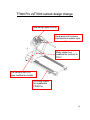
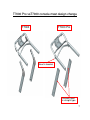
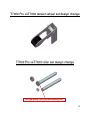
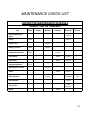
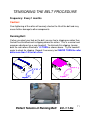
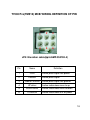
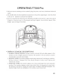
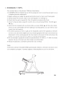
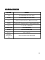
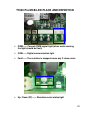
Johnson T7000 Pro
Service Manual
1
TABLE OF CONTENTS
SECTION 7: WHAT’S DIFFERENCE BETWEEN T7000 AND
T7OOOPro…………………………………….....……4
1.
2.
3.
4.
T7000 Pro vsT7000 outlook design change……………………...……...5
T7000 Pro vsT7000 internal design change…………………..…………6
T7000 Pro vsT7000 console mast design change………………………7
T7000 Pro vsT7000 tension wheel set design change…..….………….8
SECTION 2: MAINTENANCE PROCEDURE …………..…….…9
1.
2.
3.
4.
MAINTENANCE CHECK LIST………………………………...................10
TENSIONING THE BELT PROCEDURE…………………………….11-12
DECK RE-WAXING PROCEDURE……………………..……………13-14
CLEAN THE GROOVES PROCEDURE…………….............................15
SECTION 3: WIRING DIAGRAM INSTRUCTION………………..16
1.
2.
3.
4.
T7000 Pro(TM512) MCB WIRING(FOR 110V / 220V)……………….17
T7000 Pro(TM512) MCB WIRING DEFINITION OF PIN……………..18
T7000 Pro(TM512) PCB WIRING………………………..……………..19
T7000 Pro(TM512) ELECTRICAL BLOCK DIAGRAM …………....…20
SECTION 4: CONSOLE FUNCTIONAL FLOW DIAGRAM……21
1. OPERATION T7000 Pro MANUAL…………………………………….22-26
2. OPERATION T7000 Pro MANUAL- Engineer mode………………...27
2-1 Key Behalf Functions………………………………………………….28-30
SECTION 5: MCB LED INSTRUCTIONS……………… ……….31
1.
T7000 Pro MCB LED PLACE AND DEFINITION…………………….32
2
TABLE OF CONTENTS
SECTION 6: TROUBLESHOOTINGS……………..……………33
1.
2.
3.
4.
5.
6.
7.
No display on console…………………………………………………...34
Running speed is not stable…………………………………………….35
Treadmill starts to run by itself………………………………………….36
All or some of the keys on console do not work………………………36
Noises generated under motor cover………………...…………….….37
Error Messages on the Console………………………………………..38
How to make sure whether the machine hand pulse can not work…..39-40
SECTION 7: PARTS REPLACEMENT GUIDE…………..….…41
7.1
7.2
7.3
7.4
7.5
7.6
7.7
7.8
7.9
7.10
7.11
7.12
7.13
7.14
7.15
Front Plastic Shroud Removal …………………………………………42
Rear Roller Replacement……………………………………………….43
Side Rail Replacement………………………………………………….44
Front Roller Replacement………………………………………………45
Deck Removal……………………………………………………………46
Running Belt Removal ………………………………………………….47
Deck Cushion Replacement …………………………………………...48
Motor Control Board (MCB) Replacement …………………………...49
Motor Replacement……………………………………………………..50
Drive Belt Replacement ………………………………………………..51
Incline Motor Replacement …………………………………………….52
Console Control Board Replacement ………………………………...53
Console Cable Replacement ………………………………………….54
Emergency Stop Switch Replacement ……………………………….55
Heart Rate Board Replacement ………………………………………56
3
SECTION 1
What’s difference between
T7000 and 7OOOPro
4
T7000 Pro vsT7000 outlook design change
New design upper overlay
Hand pulse set has been
improved to one piece style.
Motor sticker has
modified the material to
POLY
The console mast has
been modified to straight
The frame sticker
has modified to
T7000 Pro
5
T7000 Pro vsT7000 internal design change
Power system has
been modified from
DC to AC system
Canceled the
speed sensor
New design tension
wheel set
New running belt with wax
New running
deck without
wax.
New belt
spec. 250J12
The flat type
front roller
New design donut cushion
Increase the bearing size 6
of front and back roller
T7000 Pro vsT7000 console mast design change
T7000
T7000 Pro
New fix bracket
Console mast
in straight type
7
T7000 Pro vsT7000 tension wheel set design change
T7000 Pro vsT7000 roller set design change
Flat type pulley and increase bearing size
8
SECTION 2
MAINTENANCE PROCEDURE
9
MAINTENANCE CHECK LIST
PREVENTIVE MAINTENANCE SCHEDULE
Johnson T7000 Pro TREADMILL
Item
Daily
Weekly
Monthly
Quarterly
Console Mounting
Bolts
Frame
Biannual
Inspect
Clean
Inspect
Inspect
Power Cord
Display Console
Clean
Handrail & Handlebar
Clean
Inspect
Inspect
Front Roller
Clean
Inspect
Rear Roller
Clean
Inspect
Clean
Inspect
Emergency Button
Running belt Tension
Test
Inspect
V Belt
Running Deck
Inspect
Re-waxing
Running Belt
Inspect
Control Box
Clean
(Vacuum)
Motor
Annual
Flip
Clean
10
TENSIONING THE BELT PROCEDURE
Frequency: Every 1 months
Caution:
Over-tightening of the roller will severely shorten the life of the belt and may
cause further damage to other components.
Running Belt:
If when you plant your foot on the belt, you can feel a slipping sensation then
the belt has stretched and is slipping across the rollers. This is a normal and
common adjustment on a new treadmill. To eliminate this slipping, tension
both the rear rollers Allen bolts 1/4 TURN as shown above. Try the treadmill
again to check for slipping. Repeat if necessary, but NEVER TURN the roller
bolts more than 1/4 turn at a time.
Perfect Tension of Running Belt:
0.9~1.1 lbs
11
Drive Belt:
If you have tensioned the running belt and are still experiencing a slipping,
adjust the tension screw of spring. Then try the treadmill again to check for
slipping.
12
DECK RE-WAXING PROCEDURE
Purpose : To ensure the maximum life of your treadmill, follow these steps at
regular intervals.
The timing of running belt and deck maintenance :
1.
Each 6 months to lubricate by wax powder.
2.
One year to flip the running deck.
3.
Two years or over 6,000 hrs of usage to replace new running belt and
deck.
4.
In the regular maintain, If the motor over current that has to lubricate
by wax powder
★ Take a motor current reading while a 70-90 kg user is walking on the machine at
5KM. If it is over limited current , wax the deck.
The limit current for each motor as below :
Motor type
Normal Current
Limited Current
220V DC
<9A
11A
110V DC
<15A
20A
<5A
5.5A
220V AC
110V AC
Recheck the motor current as above –
If the motor current is still over limited current, Please flip the deck or replace the
belt.
13
WAXING PROCEDURE:
1. Warm deck and belt by walking on treadmill for 3 or more minutes at a
minimum speed of 3 mph (4.8 kph).
2. Turn off and unplug the treadmill.
3. Sprinkle approximately 1/2 scales of wax under the running belt. (It is useful
to lightly blow the wax to the center of the belt.)
4. Turn the unit on and walk the wax in for 3-4 minutes at 1 mph. Walk all over
the belt to ensure smooth wax distribution.
5. Once wax is walked into the belt and deck repeat procedure for checking the
motor current to ensure that the belt and deck are not to worn for wax to
improve the friction.
Be careful to monitor wax buildup on the rollers – too much wax can cause
issues and technicians need to monitor the rollers if they continually wax units.
MTOOL-052
1/2 scale for one
machine per one time
(around 5gm)
The wax powder set
Parts number : MTOOL-052
Price : US$ 30
Wax powder set including
1.
One big bottle with 1kg wax powder
2.
A small bottle for maintenance.
14
CLEAN THE GROOVES PROCEDURE
Frequency: Every 3 months
Caution:
If dirty grooves in the drive belt and motor, there will be noises while running.
Procedure:
1.Remove the drive belt and check the
grooves in belt for dirt or dust and clean it.
2.Check the grooves in motor pulley for dirt
or dust and clean it
15
SECTION 3
WIRING DIAGRAM INSTRUCTION
16
T7000 Pro(TM512) MCB WIRING
JP3
JP4 N
L
U
V
W
W------- Motor wire (black)
JP3--------Console cable
V-------- Motor wire (white)
JP4------Elevation motor cable
U-------- Motor wire (red)
L-------- Power Input (black)
N------- Power Input (white)
17
T7000 Pro(TM512) MCB WIRING DEFINITION OF PIN
1
2
3
4
5
6
JP4: Elevation cable(6pin/AMP-350762-4)
Pin
Name
Definition
1
+VDC
2
Position
3
Ground /E driver
Incline place signal test ground
4
UP driver
Incline motor does move to up
5
DOWN driver
Incline motor does move to down
6
COMMON
Incline motor does turn on power
Incline place signal test power
Incline place signal
18
T7000 Pro(TM512) PCB WIRING(FOR 110V / 220V)
J17
J6
J19
J5
For analogy
system use only
JP2 N
J3
L
U
V
J19------- Digital communication wire port
J5--------- Hand Pulse receiver
J6--------- inbuilt receive implement
J17------- Emergency stop key
W
19
T7000 Pro(TM512) Electrical block diagram
接機台
20
SECTION 4
CONSOLE FUNCTIONAL FLOW DIAGRAM
21
OPERATING T7000 Pro
22
23
24
25
26
T7000 Pro MANUAL- Engineer mode
How to enter into the engineering mode?
1. Press & Hold both “ELEVATION ▼”
and “SPEED ▼” at the same time
for 3-5 sec. Then, the display will
show “MANAGER MENU”.
2. Press the “SPEED ▲ or ▼" to
select you want and press the
“ENTER" key enter.
Engineer mode setting
27
KEY BEHALF FUNCTION
key name
function
UP
To scroll through the list of setting
DOWN
To scroll through the list of setting
FAST
Add this show parameter of speed and elevation
SLOW
Decrease this show parameter of speed and elevation
START
To Store up the parameter
NUMBER KEY
Set the parameter
ENTER
Enter the function place
RESET
reset to sources
Hold UP &
FAST key for
3’s
clean accumulate time and distance
28
THE LIST OF MANAGER’S CUSTOM SETTING
CUSTOM SETTING
DEFAULT
MINIMUM
MAXIMUM
DESCRIPTION
P0
MAXIMUM TIME
99
10
99
Maximum workout duration.
P1
DEFAULT TIME
20
10
99
Default start time in all programs.
P2
DEFAULT LEVEL
1
1
10
Default start level in all programs.
P3
DEFAULT WEIGHT
68KG
/150LB
34KG
/75LB
159KG
/350LB
P4
DEFAULT AGE
30
10
99
P5
MAXIMUM SPEED
20 KPH
/12 MPH
P6
MAXIMUM INCLINE
15%
P7
ACCUMULATED
DISTANCE
N/A
N/A
N/A
Total distance on treadmill, not
editable. TO RESET: Press and
hold INCLINE DOWN and
SPEED DOWN for 3-5 seconds.
P8
ACCUMULATED
TIME
N/A
N/A
N/A
Total distance on treadmill, not
editable. TO RESET: Press and
hold INCLINE DOWN and
SPEED DOWN for 3-5 seconds.
P9
START SPEED
0.8 KPH
/ 0.5 MPH
0.8 KPH
/ 0.5 MPH
3.0 KPH
/ 1.8 MPH
Controls the starting speed for
all programs (does not affect
minimum speeds).
P10
PAUSE TIME
60 sec
30 sec
180 sec
Controls the maximum time
the treadmill can be paused
during a workout.
P11
LANGUAGE
English
N/A
N/A
Sets the language shown on the
console.
P12
UCB SOFT. VER.
N/A
N/A
N/A
Software Version of UCB, not
editable.
P13
MCB SOFT. VER.
N/A
N/A
N/A
Software Version of MCB, not
editable.
P14
UNITS
Metric
N/A
N/A
Measurement unit used for
calorie calculations,
distance, and speed.
6.4 KPH
/ 4.0 MPH
20 KPH
/ 12.0 MPH
4% , 8% , 12% , 15%
(CONTINUE)
Default weight used in calorie
calculations and HR programs.
Default age used in HR programs.
Controls the maximum speed for
all programs.
Controls the maximum incline for
all programs.
29
THE LIST OF MANAGER’S CUSTOM SETTING
CUSTOM SETTING
DEFAULT
MINIMUM
MAXIMUM
DESCRIPTION
P15
MAINTEN.
REMINDER
ON
N/A
N/A
Controls the distance
accumulative to maintenance. If
default ON will can to select goal
distance accumulative.
4000~8000KM , 2500~5000 Mile.
P16
AUTO CHECK
N/A
N/A
N/A
This function is to calibrate
the treadmill incline.
P17
ERROR LOG
N/A
N/A
N/A
This function is to record the error
occur history.
P18
RESET ALL
N/A
N/A
N/A
This function is to reset all
parameter.
P19
MANUFATURING
TEST
N/A
N/A
N/A
For factory use only.
Remarks
If you on P19: MANUFACTURING TEST this ADDRESS place, you can
hold the number key “1 and 3” for 3’s enter MANUFACTURING TEST .
ADDRESS
description
M0
TEST
M1
Low speed
M2
High speed
M3
RPM Parameter
30
SECTION 5
T7000 Pro MCB LED INSTRUCTIONS
31
T7000 Pro MCB LED PLACE AND DEFINITION
PWM------ Console PWM signal light (when motor running
the light should be flash)
COM------ Digital communication light
Fault------ The machine is stopped cause any C class errors
Up / Down (FF)------ Elevation motor status light
32
SECTION 6
TROUBLESHOOTINGS
33
No display on console
Possible causes:
1.
Breaker is damaged.
2.
ON/OFF switch is damaged.
3.
MCB is damaged
4.
Digital communication cable is damaged
5.
PCB is damaged
Fix:
1.
Inspect the circuit breaker to see if it has tripped off.
(If it is tripped off….like diagram B, reset the breaker. And check
which part is short-circuited. Then replace the short-circuited part.)
A
B
2.
The switch is turned to the "ON" position.
( If the switch light isn't lit, replace the switch.)
2-1 Verify wire connection N & L on the MCB.
(Please refer the” MCB WIRING” ……page 17)
3. Verify the MCB whether supply the +12VDC for console.
4. Replace digital communication cable .
5. Replace PCB
34
Running speed is not stable
Possible causes:
1.
AC power voltage is too low.
2.
Tension of drive belt or running belt is too loose.
3.
MCB is damaged.
4.
Motor is damaged.
Fix:
1.
Check the power voltage by using voltage-meter to see if it is within
120V±15% or 230V±15%.
If the power voltage isn't within the range, look for a qualified
electrician for help.
2. Open the motor cover, if the belt has stretched and is slipping across the
rollers when running.
Adjust the belt tension (Please refer the” TENSIONING THE BELT
PROCEDURE”……. Page11~12).
2.
Replace new MCB.
3.
Replace new Motor.
35
Treadmill starts to run by itself
Possible causes:
1.
The digital communication cable is broken.
2.
PCB is out of order.
3.
MCB is out of order.
Fix:
1.
Replace the console cable with a new one.
2.
Replace the PCB.
3.
Replace the MCB.
All or some of the keys on console do not work
Possible causes:
1.
Keypad connecting plug is not fit-in properly.
2.
Keypad is damaged.
3.
PCB is damaged.
Fix:
1.
Disconnect the keypad and replace the keypad, and check again.
2.
Replace the keypad.
3.
Replace the PCB.
36
Noises generated under motor cover
Possible causes:
1.
The running belt tension is adjusted too tight.
2.
The bearing of front roller is not installed correctly.
3.
Dirty grooves of drive belt.
4.
The motor is damaged.
Fix:
1.
Adjust the belt tension so that the belt does not start slipping and
then check if the noise has disappeared.
Let the treadmill run, without
using it, for at least 5 days
because sometimes the bearing
will settle and become quiet
then check if the noise has
disappeared.
2.
3.
4.
Replace the front roller with a new one to see if the noise disappear.
Remove drive-belt and check the grooves in belt for dirt or dust and
clean if necessary. Clean also the motor pulley and the roller pulley
grooves and check if the noise has disappeared.
The motor bearing is damaged.
Replace the motor.
37
Error Messages on the Console
Class
Level
Error
Code
B
0140
C
01A0
C
01A4
C
01A5
C
01A6
C
01A8
C
01AB
C
01AD
C
02A0
C
02A1
C
02A2
C
02A8
C
02AD
C
02B5
C
02B6
C
02B7
C
02B8
C
02B9
C
02BA
C
02BC
C
02BD
Description
Conditioned
Solution
when the elevation is supposed to move, it does
1. connection check
not move. When the error happens, the elevation
Incline motor operation fail.
2. MCB LED check
will be locked. The command "initialize" is
3. incline motor check or replace
needed to unlock the elevation.
1. connection check
when the elevation position cable is not
Incline motor disconnection
2. MCB LED check
connected
3. incline motor check or replace
Main motor U phase
Main motor U phase disconnection
1. connection check U
disconnection
Main motor V phase
Main motor V phase disconnection
2. connection check V
disconnection
Main motor W phase
Main motor W phase disconnection
3. connection check W
disconnection
1. connection check
main motor over current
main motor over current 7Amps
2. lubrication
3. overload
1. check MCB error by PU-01
Inverter Error
internal error of inverter
2. MCB replacement
Inner electron over
when the user over 130kg to make motor over
temperature : motor over
Lubrication running belt
loading and Inner electron over temperature
loading.
1. connection check (power input )
the belt does not move when it supposes to
main motor fail
2. motor resistance check
move
3. MCB replacement
Over AC power input
check power input
power input voltage over range
voltage
Over / low DC bus voltage power input voltage over range
check power input
Inverter circuit of motor
1. motor check or replace
motor resistance close.
driver fail
1. check MCB temp. by PU-01
LCB over temperature
LCB over temperature
2. check cool fan
3. MCB replacement
Inverter sensor the normal
Inverter sensor the normal rated current over
rated current over 150% ,
motor check or replace
10.5Amps , can hold 60 sec.)
can hold 60 sec.
Speed up have over
Lubrication
Software discover
current.
Speed down have over
MCB replacement
Software discover
current.
1. connection check
Running status over current. Software discover
2. lubrication
3. overload
The inner memory IC data
MCB replacement
MCB fail
write error
The inner memory IC data
MCB replacement
MCB fail
read error
Ground connection or fuse
MCB replacement
MCB fail
error
Inverter hardware interrupt
MCB replacement
MCB fail
error
Class Level--Level--Class C : The machine will be stop.
Class B : To make a record in error log only, The machine keep working.
38
How to make sure whether the machine hand pulse can not work
1. Please make sure then user hold the hand pulse whether windows show picture.
Remark: Heart rate figure show up on the screen about in 5~10 sec.
2. If the heart rate figure still doesn't show up on the screen, Please inspect
according to the step as below.
Step 1: Using multi-meter to confirm the wire has conduct.
39
Step 2: Please check the connection.
Check whether the heart rate cable is touching hand pulse metal (both of left hand
and right hand).
Besides the other side of the heart rate cable should be connected with HR board.
Step 3: If you can't find any problem with above step, and the heart rate
figure still can't show up, Please replace the heart rate board.
40
SECTION 7
Part Replacement Guide
7.1 Front Plastic Shroud Removal
7.2 Rear Roller Replacement
7.3 Side Rail Replacement
7.4 Front Roller Replacement
7.5 Deck Removal
7.6 Running Belt Removal
7.7 Deck Cushion Replacement
7.8 Motor Control Board (MCB) Replacement
7.9 Motor Replacement
7.10 Drive Belt Replacement
7.11 Incline Motor Replacement
7.12 Console Control Board Replacement
7.13 Console Cable Replacement
7.14 Emergency Stop Switch Replacement
7.15 Heart Rate Board Replacement
41
CHAPTER 7: Part Replacement Guide
7.1 Front Plastic Shroud Removal
1) Turn off the power and move the plug
2) Remove the eight fix screws of front shroud using a Phillips screwdriver
(Figures A & B).
42
CHAPTER 7: Part Replacement Guide
7.2 Rear Roller Replacement
1) Turn off power and disconnect the cord from the machine.
2) Remove both side end caps using a Phillips screwdriver (Figure A).
3) Remove both roller adjustment screws using an 8 mm Allen wrench (Figure B).
4) Remove the roller from the running belt (Figures C).
5) Reverse Steps 1-4 to install a new roller
A
A
C
B
43
CHAPTER 7: Part Replacement Guide
7.3 Side Rail Replacement
1) Remove the front shroud as outlined in Section 7.1.
2) Remove the end cap using a Phillips screwdriver (Figure A).
3) Remove the end cap bracket using a 3 mm Allen wrench (Figure B).
4) Slide the rail off the back of the treadmill (Figures C).
5) Reverse Steps 1-4 to install a new side rail.
A
A
B
C
44
CHAPTER 7: Part Replacement Guide
7.4 Front Roller Replacement
1)
Remove the front shroud as outlined in Section 7.1.
2)
Release the tension of running belt
3)
Remove the fix bolt of tension wheel set using a 5 mm Allen wrench (Figure A) Be
careful to hold the tension wheel set when fix bolt is releasing.
4)
Remove the fix bolts of front roller using a 5 mm Allen wrench (Figure B)
5)
Remove the driver belt form front roller. (Figure C)
6)
Remove the front roller from the running belt
7)
Reverse Steps 1-6 to install a new roller
A
B
C
45
CHAPTER 7: Part Replacement Guide
7.5 Deck Removal
1)
Remove the front shroud as outlined in Section 7.1.
2)
Remove the side rail as outlined in Section 7.3.
3)
Remove the eight deck screws using a 5 mm Allen wrench (Figure A).
4)
Loose the tension of running belt
5)
Remove the deck from the running belt
6)
Be careful not to pinch fingers during removal / installation of deck board.
46
CHAPTER 7: Part Replacement Guide
7.6 Running Belt Removal
1) Remove the front shrouds as outlined in Section 7.1.
2) Remove the rear roller as outlined in Section 7.2.
3) Remove the side rail as outlined in Section 7.3.
4) Remove the front roller as outlined in Section 7.4.
5) Remove the deck as outlined in Section 7.5
6) Remove the running belt and replace with a new belt
7) Reverse Steps 1-6 to install a new running belt.
47
CHAPTER 7: Part Replacement Guide
7.7 Deck Cushion Replacement
1) Remove the front shrouds as outlined in Section 7.1.
2) Remove the rear roller as outlined in Section 7.2.
3) Remove the side rail as outlined in Section 7.3.side rail as outlined in Section 7.3.
4) Remove the deck as outlined in Section 7.5.
5) Remove the running belt as outlined in Section 7.6
6) Remove the front roller as outlined in Section 7.4.
7) Holding the bolt with a 5 mm Allen wrench, loosen the nut with a 13 mm socket
(Figure A & B).
A
B
48
CHAPTER 7: Part Replacement Guide
7.8 Motor Control Board (MCB) Replacement
1) Turn off power and disconnect the cord from the machine.
2) Remove the front shroud as outlined in Section 7.1.
3) Cut any wire ties that are secured to the MCB panel (Figure A, B).
4) Disconnect wires from the MCB - six total connections (Figure C).
5) Remove Four MCB mounting screws using a Phillips head screwdriver (Figures D).
6) Reverse Steps 1-5 to install a new MCB.
7) Auto Calibration must ALWAYS be run after replacing the MCB (see Section 3.2).
A
B
C
D
49
CHAPTER 7: Part Replacement Guide
7.9 Motor Replacement
1) Turn off power and disconnect the cord from the machine.
2) Remove the front shroud as outlined in Section 7.1.
3) Release the drive belt tensioner as outlined in Section 7.5.
4) Disconnect the motor power cable from the MCB (Figure A).
5) Using an 8 mm Allen wrench, remove the four motor mounting screws (Figure B).
6) Lift the motor away from the treadmill
7) Reverse Steps 1-6 to install a new motor.
8) When reinstalling the motor, make sure the vibration pad is in place.
9) Be careful the diversion when motor remove and reinstall. (Figure C)
A
B
C
50
CHAPTER 7: Part Replacement Guide
7.10 Drive Belt Replacement
1) Remove the front shroud as outlined in Section 7.1.
2) Release the drive belt tension wheel set from drive belt as outlined in Section 7.4.
3) Remove the front roller screws on both side (Figure A).
4) Lift the roller and remove the old drive belt
5) After installing a new belt, check it for correct alignment to the motor pulley before
setting the tension wheel set in place.
A
A
51
CHAPTER 7: Part Replacement Guide
7.11 Incline Motor Replacement
1) Turn off power and disconnect the cord from the machine.
2) Lift the treadmill and support it so that the front wheels are off the floor, or the unit
may be tipped on its side (Figure A).
3) Disconnect the incline motor power cable from the MCB (Figure B).
4) Disconnect the bolt from the incline motor (Figure C).
5) Lift the incline motor away from the treadmill.
6) When installing the new incline motor, make sure to replace the white washers at
the top and bottom.
7) Auto Calibration must ALWAYS be run after replacing the incline motor (see
Section 3.2).
A
B
B
C
C
52
CHAPTER 7: Part Replacement Guide
7.12 Console control board Replacement
1)
Turn off power and disconnect the cord from the machine.
2)
Remove the four 6 mm screws using a Phillips head screwdriver from underneath
the console to open the upper console cover. (Figure A).
3)
Disconnect all of the wires from the console control board. (Figure B).
4)
Remove the seven fix screws of CCB using a Phillips head screwdriver. (Figure C).
5)
Reverse Steps 1-4 to install a new console control board.
6)
Auto Calibration must ALWAYS be run after replacing the console (see Section
3.2).
A
B
C
53
CHAPTER 7: Part Replacement Guide
7.13 Console Cable Replacement
1) Turn off power and disconnect the cord from the machine.
2) Open the upper console cover as outlined in Section 7.12-2.
3) Disconnect the console wire from CCB (Figure A).
4) Connection the defect wire and new wire (Figure B).
5) Pull the defect wire from lower outlet of console mast.
6) Reconnect console wire to MCB and CCB.
A
B
54
CHAPTER 7: Part Replacement Guide
7.14 Emergency Stop Switch Replacement
A
1)
Turn off power and disconnect the cord from the machine.
2)
Open the upper console cover as outlined in Section 7.12-2.
3)
Use a Phillips screwdriver to remove two screws of the cover of Emergency key
(Figure A).
4)
Use a Phillips screwdriver to remove two screws of the base of Emergency key
(Figure B).
5)
Turn open the Emergency switch (Figure C).
6)
Reverse Steps 1-5 to install a new Emergency key set
B
C
55
OK
CHAPTER 7: Part Replacement Guide
7.15 Heart Rate Board Replacement
1)
Turn off power and disconnect the cord from the machine.
2)
Open the upper console cover as outlined in Section 7.12-2.
3)
Disconnect the wires from each side of the Heart Rate Board (Figure A).
4)
Use a Phillips screwdriver to remove two screws, one from each side of
the Heart Rate Board mounting bracket (Figure B).
5)
Be sure to fully seat the wires on the new Heart Rate Board and test the
grips after the console is reinstalled.
A
A
B
56