1
Outputs and Inputs
11.2.1.2
Installation
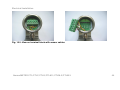
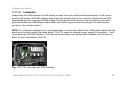
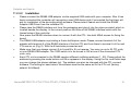
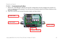
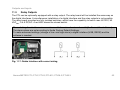
Please plug the USB interface into the place provided, which is located beside the display. In the correct
position the holes of the USB interface match with the thread holes of the controller. Now press the PCB
downwards and fix it using both M3x5 screws. Exchange the blind screw on the controller by the cable
gland and install the USB adapter cable. Make sure the wiring is correct according to the wire colours
printed on the interface board.
NOTE: For industrial installations it is recommended to connect the shield of the USB adapter cable with the
electronics housing (inside the cable gland). The CTL needs no external power supply for operation – it will
be powered by the USB interface. If an external power supply has already been installed, this will have no
effect on the functionality of the CTL.
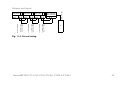
Fig. 11.2: CTL controller with USB Interface
thermoMETER CTL/CTLF/CTLG/CTLM-1/CTLM-2/CTLM-3
48