1
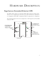
TigerAccess
Extended Ethernet CPE
Extended Ethernet VDSL CPE
High-speed Internet access over existing phone lines
Concurrent data and telephone services (voice/ISDN)
over a single connection
Supports evolving ETSI, ANSI, and ITU VDSL
standards for the copper local loop
Supports power back-off algorithm that permits a mixed
distance deployment
Easy installation
User Guide
SMC7500A/VCP
TigerAccess Extended Ethernet CPE
User Guide
From SMC’s Tiger line of feature rich connectivity solutions
38 Tesla
Irvine, CA 92618
Phone: (949) 679-8000
October 2002
Part No: 750.5871
Pub No: 150000010900A R02
Copyright
Information furnished by SMC Networks, Inc. (SMC) is believed to be accurate and reliable.
However, no responsibility is assumed by SMC for its use, nor for any infringements of
patents or other rights of third parties which may result from its use. No license is granted by
implication or otherwise under any patent or patent rights of SMC. SMC reserves the right to
change specifications at any time without notice.
Copyright © 2002 by
SMC Networks, Inc.
38 Tesla, Irvine, CA.
All rights reserved. Printed in Taiwan
Trademarks:
SMC is a registered trademark; and TigerAccess is a trademark of SMC Networks, Inc. Other
product and company names are trademarks or registered trademarks of their respective
holders.
LIMITED WARRANTY
Limited Warranty Statement: SMC Networks, Inc. (“SMC”) warrants its products to be
free from defects in workmanship and materials, under normal use and service, for the
applicable warranty term. All SMC products carry a standard 90-day limited warranty from
the date of purchase from SMC or its Authorized Reseller. SMC may, at its own discretion,
repair or replace any product not operating as warranted with a similar or functionally
equivalent product, during the applicable warranty term. SMC will endeavor to repair or
replace any product returned under warranty within 30 days of receipt of the product.
The standard limited warranty can be upgraded to a Limited Lifetime* warranty by registering
new products within 30 days of purchase from SMC or its Authorized Reseller. Registration
can be accomplished via the enclosed product registration card or online via the SMC web
site. Failure to register will not affect the standard limited warranty. The Limited Lifetime
warranty covers a product during the Life of that Product, which is defined as the period of
time during which the product is an “Active” SMC product. A product is considered to be
“Active” while it is listed on the current SMC price list. As new technologies emerge, older
technologies become obsolete and SMC will, at its discretion, replace an older product in its
product line with one that incorporates these newer technologies. At that point, the obsolete
product is discontinued and is no longer an “Active” SMC product. A list of discontinued
products with their respective dates of discontinuance can be found at
http://www.smc.com/index.cfm?action=customer_service_warranty
All products that are replaced become the property of SMC. Replacement products may be
either new or reconditioned. Any replaced or repaired product carries either a 30-day limited
warranty or the remainder of the initial warranty, whichever is longer. SMC is not responsible
for any custom software or firmware, configuration information, or memory data of
Customer contained in, stored on, or integrated with any products returned to SMC pursuant
to any warranty. Products returned to SMC should have any customer-installed accessory or
add-on components, such as expansion modules, removed prior to returning the product for
replacement. SMC is not responsible for these items if they are returned with the product.
Customers must contact SMC for a Return Material Authorization number prior to returning
any product to SMC. Proof of purchase may be required. Any product returned to SMC
without a valid Return Material Authorization (RMA) number clearly marked on the outside
of the package will be returned to customer at customer’s expense. For warranty claims within
North America, please call our toll-free customer support number at (800) 762-4968.
Customers are responsible for all shipping charges from their facility to SMC. SMC is
responsible for return shipping charges from SMC to customer.
i
LIMITED WARRANTY
WARRANTIES EXCLUSIVE: IF AN SMC PRODUCT DOES NOT OPERATE AS
WARRANTED ABOVE, CUSTOMER’S SOLE REMEDY SHALL BE REPAIR OR
REPLACEMENT OF THE PRODUCT IN QUESTION, AT SMC’S OPTION. THE
FOREGOING WARRANTIES AND REMEDIES ARE EXCLUSIVE AND ARE IN
LIEU OF ALL OTHER WARRANTIES OR CONDITIONS, EXPRESS OR IMPLIED,
EITHER IN FACT OR BY OPERATION OF LAW, STATUTORY OR OTHERWISE,
INCLUDING WARRANTIES OR CONDITIONS OF MERCHANTABILITY AND
FITNESS FOR A PARTICULAR PURPOSE. SMC NEITHER ASSUMES NOR
AUTHORIZES ANY OTHER PERSON TO ASSUME FOR IT ANY OTHER
LIABILITY IN CONNECTION WITH THE SALE, INSTALLATION,
MAINTENANCE OR USE OF ITS PRODUCTS. SMC SHALL NOT BE LIABLE
UNDER THIS WARRANTY IF ITS TESTING AND EXAMINATION DISCLOSE THE
ALLEGED DEFECT IN THE PRODUCT DOES NOT EXIST OR WAS CAUSED BY
CUSTOMER’S OR ANY THIRD PERSON’S MISUSE, NEGLECT, IMPROPER
INSTALLATION OR TESTING, UNAUTHORIZED ATTEMPTS TO REPAIR, OR
ANY OTHER CAUSE BEYOND THE RANGE OF THE INTENDED USE, OR BY
ACCIDENT, FIRE, LIGHTNING, OR OTHER HAZARD.
LIMITATION OF LIABILITY: IN NO EVENT, WHETHER BASED IN CONTRACT
OR TORT (INCLUDING NEGLIGENCE), SHALL SMC BE LIABLE FOR
INCIDENTAL, CONSEQUENTIAL, INDIRECT, SPECIAL, OR PUNITIVE
DAMAGES OF ANY KIND, OR FOR LOSS OF REVENUE, LOSS OF BUSINESS, OR
OTHER FINANCIAL LOSS ARISING OUT OF OR IN CONNECTION WITH THE
SALE, INSTALLATION, MAINTENANCE, USE, PERFORMANCE, FAILURE, OR
INTERRUPTION OF ITS PRODUCTS, EVEN IF SMC OR ITS AUTHORIZED
RESELLER HAS BEEN ADVISED OF THE POSSIBILITY OF SUCH DAMAGES.
SOME STATES DO NOT ALLOW THE EXCLUSION OF IMPLIED WARRANTIES
OR THE LIMITATION OF INCIDENTAL OR CONSEQUENTIAL DAMAGES FOR
CONSUMER PRODUCTS, SO THE ABOVE LIMITATIONS AND EXCLUSIONS
MAY NOT APPLY TO YOU. THIS WARRANTY GIVES YOU SPECIFIC LEGAL
RIGHTS, WHICH MAY VARY FROM STATE TO STATE. NOTHING IN THIS
WARRANTY SHALL BE TAKEN TO AFFECT YOUR STATUTORY RIGHTS.
* SMC will provide warranty service for one year following discontinuance from the active
SMC price list. Under the limited lifetime warranty, internal and external power supplies, fans,
and cables are covered by a standard one-year warranty from date of purchase.
SMC Networks, Inc.
38 Tesla
Irvine, CA 92618
ii
COMPLIANCES
FCC - Class B
This equipment has been tested and found to comply with the limits for a Class B digital
device, pursuant to Part 15 of the FCC Rules. These limits are designed to provide reasonable
protection against harmful interference in a residential installation. This equipment generates,
uses and can radiate radio frequency energy and, if not installed and used in accordance with
instructions, may cause harmful interference to radio communications. However, there is no
guarantee that the interference will not occur in a particular installation. If this equipment
does cause harmful interference to radio or television reception, which can be determined by
turning the equipment off and on, the user is encouraged to try to correct the interference by
one or more of the following measures:
•
Reorient the receiving antenna
•
Increase the separation between the equipment and receiver
•
Connect the equipment into an outlet on a circuit different from that to
which the receiver is connected
•
Consult the dealer or an experienced radio/TV technician for help
Note:
In order to maintain compliance with the limits of a Class B digital device, SMC
requires that you use a quality interface cable when connecting to this device.
Changes or modifications not expressly approved by SMC could void the user’s
authority to operate this equipment.
Industry Canada - Class B
This digital apparatus does not exceed the Class B limits for radio noise emissions from
digital apparatus as set out in the interference-causing equipment standard entitled “Digital
Apparatus,” ICES-003 of Industry Canada.
Cet appareil numérique respecte les limites de bruits radioélectriques applicables aux appareils
numériques de Classe B prescrites dans la norme sur le matérial brouilleur: “Appareils
Numériques,” NMB-003 édictée par l’Industrie.
Japan VCCI Class B
iii
COMPLIANCES
EC Conformance Declaration - Class B
SMC contact for these products in Europe is:
SMC Networks Europe,
Edificio Conata II,
Calle Fructuós Gelabert 6-8, 2o, 4a,
08970 - Sant Joan Despí,
Barcelona, Spain.
This information technology equipment complies with the requirements of the Council
Directive 89/336/EEC on the Approximation of the laws of the Member States relating to
Electromagnetic Compatibility and 73/23/EEC for electrical equipment used within certain
voltage limits and the Amendment Directive 93/68/EEC. For the evaluation of the
compliance with these Directives, the following standards were applied:
RFI Emission:
• Limit class B according to EN 55022:1998
• Limit class A for harmonic current emission according to
EN 61000-3-2/1995
• Limitation of voltage fluctuation and flicker in low-voltage supply
system according to EN 61000-3-3/1995
Immunity:
• Product family standard according to EN 55024:1998
• Electrostatic Discharge according to EN 61000-4-2:1995
(Contact Discharge: ±4 kV, Air Discharge: ±8 kV)
• Radio-frequency electromagnetic field according to EN 61000-4-3:1996
(80 - 1000MHz with 1kHz AM 80% Modulation: 3V/m)
• Electrical fast transient/burst according to EN 61000-4-4:1995 (AC/
DC power supply: ±1 kV, Data/Signal lines: ±0.5kV)
• Surge immunity test according to EN 61000-4-5:1995
(AC/DC Line to Line: ±1 kV, AC/DC Line to Earth: ±2 kV)
• Immunity to conducted disturbances, Induced by radio-frequency
fields: EN 61000-4-6:1996 (0.15 - 80MHz with
1kHz AM 80% Modulation: 3V/m)
• Power frequency magnetic field immunity test according to
EN 61000-4-8:1993 (1 A/m at frequency 50 Hz)
• Voltage dips, short interruptions and voltage variations immunity test
according to EN 61000-4-11:1994 (>95% Reduction @10 ms, 30%
Reduction @500 ms, >95% Reduction @5000 ms)
Warning! Do not plug a phone jack connector in the RJ-45 port. This may damage the device.
Les raccordeurs ne sont pas utilisé pour le système téléphonique!
iv
COMPLIANCES
Safety Compliance
Underwriters laboratories Inc. (USA)
Important! Before making connections, make sure you have the correct Cord Set. Check it
(read the label on the cable) against the following specification list.
Operating Voltage
Cord Set Specifications
120 Volts
UL Listed/CSA Certified Cord Set
Minimum 18 AWG
Type SVT or SJT three conductor cord
Maximum length of 4.6 m (15 ft)
Parallel blade, grounding type attachment plug rated
15A, 125 V
240 Volts (Europe only)
Cord Set with H05VV-F cord having three conductors with
minimum diameter of 0.75 mm2
IEC-320 receptacle
Male plug rated 10 A, 250 V
Wichtige Sicherheitshinweise (Germany)
1. Bitte lesen Sie diese Hinweise sorgfältig durch.
2. Heben Sie diese Anleitung für den späteren Gebrauch auf.
3. Vor jedem Reinigen ist das Gerät vom Stromnetz zu trennen. Verwenden Sie keine Flüssigoder Aerosolreiniger. Am besten eignet sich ein angefeuchtetes Tuch zur Reinigung.
4. Die Netzanschlu ßsteckdose soll nahe dem Gerät angebracht und leicht zugänglich sein.
5. Das Gerät ist vor Feuchtigkeit zu schützen.
6. Bei der Aufstellung des Gerätes ist auf sicheren Stand zu achten. Ein Kippen oder Fallen
könnte Beschädigungen hervorrufen.
7. Die Belüftungsöffnungen dienen der Luftzirkulation, die das Gerät vor Überhitzung
schützt. Sorgen Sie dafür, daß diese Öffnungen nicht abgedeckt werden.
8. Beachten Sie beim Anschluß an das Stromnetz die Anschlußwerte.
9. Verlegen Sie die Netzanschlußleitung so, daß niemand darüber fallen kann. Es sollte auch
nichts auf der Leitung abgestellt werden.
10. Alle Hinweise und Warnungen, die sich am Gerät befinden, sind zu beachten.
11. Wird das Gerät über einen längeren Zeitraum nicht benutzt, sollten Sie es vom Stromnetz
trennen. Somit wird im Falle einer Überspannung eine Beschädigung vermieden.
12. Durch die Lüftungsöffnungen dürfen niemals Gegenstände oder Flüssigkeiten in das
Gerät gelangen. Dies könnte einen Brand bzw. elektrischen Schlag auslösen.
13. Öffnen sie niemals das Gerät. Das Gerät darf aus Gründen der elektrischen Sicherheit
nur von authorisiertem Servicepersonal geöffnet werden.
v
COMPLIANCES
14. Wenn folgende Situationen auftreten ist das Gerät vom Stromnetz zu trennen und von
einer qualifizierten Servicestelle zu überprüfen:
a.
b.
c.
d.
Netzkabel oder Netzstecker sind beschädigt.
Flüssigkeit ist in das Gerät eingedrungen.
Das Gerät war Feuchtigkeit ausgesetzt.
Wenn das Gerät nicht der Bedienungsanleitung entsprechend funktioniert oder Sie mit
Hilfe dieser Anleitung keine Verbesserung erzielen.
e. Das Gerät ist gefallen und/oder das Gehäuse ist beschädigt.
f. Wenn das Gerät deutliche Anzeichen eines Defektes aufweist.
15. Stellen Sie sicher, daß die Stromversorgung dieses Gerätes nach der EN 60950 geprüft ist.
Ausgangswerte der Stromversorgung sollten die Werte von AC 7,5-8V, 50-60Hz nicht
über oder unterschreiten sowie den minimalen Strom von 1A nicht unterschreiten.
Der arbeitsplatzbezogene Schalldruckpegel nach DIN 45 635 Teil 1000 beträgt 70dB(A) oder
weniger.
vi
TABLE OF CONTENTS
TigerAccess Extended Ethernet CPE . . . . . . . . . . . . . . 1
Introduction . . . . . . . . . . . . . . . . . . . . . . . . . . . . . . . . . . . . . . . . . . . . . . . . . 1
VDSL Technology . . . . . . . . . . . . . . . . . . . . . . . . . . . . . . . . . . . . . . . . . . . . 3
Features and Benefits . . . . . . . . . . . . . . . . . . . . . . . . . . . . . . . . . . . . . . . . . . 4
Package Checklist . . . . . . . . . . . . . . . . . . . . . . . . . . . . . . . . . . . . . . . . . . . . . 5
System Requirements . . . . . . . . . . . . . . . . . . . . . . . . . . . . . . . . . . . . . . . . . . 6
Hardware Description . . . . . . . . . . . . . . . . . . . . . . . . . . . 7
TigerAccess Extended Ethernet CPE . . . . . . . . . . . . . . . . . . . . . . . . . . . . . 7
LED Status . . . . . . . . . . . . . . . . . . . . . . . . . . . . . . . . . . . . . . . . . . . . . . . . . . 8
Installation . . . . . . . . . . . . . . . . . . . . . . . . . . . . . . . . . . . . 9
Overview . . . . . . . . . . . . . . . . . . . . . . . . . . . . . . . . . . . . . . . . . . . . . . . . . . . . 9
Mounting . . . . . . . . . . . . . . . . . . . . . . . . . . . . . . . . . . . . . . . . . . . . . . . . . . . 9
Cable Connections . . . . . . . . . . . . . . . . . . . . . . . . . . . . . . . . . . . . . . . . . . . 10
Powering On . . . . . . . . . . . . . . . . . . . . . . . . . . . . . . . . . . . . . . . . . . . . . . . 11
Configuring the TCP/IP Protocols . . . . . . . . . . . . . . . . . . . . . . . . . . . . . . 11
Troubleshooting . . . . . . . . . . . . . . . . . . . . . . . . . . . . . . 14
Diagnosing CPE Indicators . . . . . . . . . . . . . . . . . . . . . . . . . . . . . . . . . . . . 14
If You Cannot Connect to the Internet . . . . . . . . . . . . . . . . . . . . . . . . . . 15
Port And Cable Assignments . . . . . . . . . . . . . . . . . . . . . . . . . . . . . . . . . . . 15
Straight-Through Cable . . . . . . . . . . . . . . . . . . . . . . . . . . . . . . . . . . . . . . . 16
Crossover Cable . . . . . . . . . . . . . . . . . . . . . . . . . . . . . . . . . . . . . . . . . . . . . 17
RJ-11 Ports . . . . . . . . . . . . . . . . . . . . . . . . . . . . . . . . . . . . . . . . . . . . . . . . . 17
Specifications . . . . . . . . . . . . . . . . . . . . . . . . . . . . . . . . . 19
vii
TABLE OF CONTENTS
viii
TIGERACCESS EXTENDED
ETHERNET CPE
Introduction
SMC’s TigerAccess Extended Ethernet CPE system consists of end-user
CPE (Customer Premise Equipment) and a VDSL switch that are
connected by standard telephone cable. The VDSL connection delivers an
Ethernet data link rated up to 15 Mbps symmetric (full duplex), while
simultaneously supporting standard telephone services. The system can be
deployed in any multi-dwelling/multi-tenant environment (apartment
blocks, hotels, or office complexes) to provide both high-speed Internet
access and telephone services without any need for re-wiring.
SMC’s VDSL switches combine both the data and phone signals coming
from your Internet and telephone service providers, and pass these signals
directly over standard telephone wiring to multiple users in the same
building. The SMC7500A/VCP CPE is used to separate these signals and
pass them on to a customer’s computer and telephone equipment.
In-building connections operate at up to 15 Mbps over runs up to 1070 m
(3500 ft), 10 Mbps for runs up to 1220 m (4500 ft), 5 Mbps for runs up to
1370 m (4500 ft) and asymmetric 4 Mbps downstream/1 Mbps upstream
at up to 1770 m (5800 ft).
The VDSL switch is typically located in a wiring closet or other central
location of a multi-dwelling/multi-tenant unit, campus, or enterprise. An
Internet connection is provided from the ISP to the customer’s building
over fiber optic cable, running Ethernet directly over a 1 Gbps (or future
10 Gbps) connection. This kind of WAN connection is referred to as Fiber
To The Building (FTTB). Data signals entering a site are first passed
through an Ethernet switch that segregates the signals for individual user
connections, and are then fed into the switch. Phone signals are also
routed from PBX/MDF distribution equipment into the switch. The data
1
TIGERACCESS EXTENDED ETHERNET CPE
and phone signals for each user are combined in the switch, and passed
over VDSL lines to individual customers.
The SMC7500A/VCP CPE at the customer end of the VDSL line
connects to any PC or Macintosh equipped with a 10/100BASE-TX
network interface card. Your existing telephone, modem, or fax machine
simply plugs into the CPE’s phone port. There is no need for special
splitters, terminators, or filters. In fact, there is no need to modify the
home wiring at all and, because the VDSL connection is based on
Ethernet, no further complex software configurations are required.
2
VDSL TECHNOLOGY
VDSL Technology
VDSL (Very High Bit-Rate Digital Subscriber Line) is at the high-end of
the DSL technologies, offering the best combination of fiber optics and
copper to provide high-speed broadband Internet access. VDSL’s primary
application is in providing a broadband data service to multi-tenant
residential or commercial buildings. In this implementation, fiber optic
cable carries data from a telephone company’s central office to the
building; then the installed telephone copper wires take the data and
deliver it to individual units within that building.
Telephone
Rooms/Clients
VDSL CPE
Floor 2
Telephone/Fax
Rooms/Clients
Existing Phone
Lines to Clients
Punch Down
Blocks /
Patch Panels
Floor 1
VDSL CPE
VDSL
Concentrators
VDSL Lines
Local Servers
(Locally Hosted Services,
Video Servers, Billing)
Ethernet
Switch
1
Phone Lines
PBX
ES3526F
Fiber Optic Link to ISP
Ethernet
Links to Switch
Telephone Line from Central Office
ISP
(Internet)
Central Office
(PSTN)
Multi-dwelling/Multi-tenant Building
VDSL provides high-speed Internet access over existing phone lines by
making use of previously unused frequency bandwidth above the voice
band. By placing VDSL signals above the frequency of the voice signal, a
VDSL service can coexist on the same line with other telephone services.
VDSL can operate symmetrically, providing the same data rate in both
directions, or asymmetrically, providing a higher data rate in the
downstream (receive) direction than in the upstream (transmit) direction.
3
TIGERACCESS EXTENDED ETHERNET CPE
VDSL delivers high-performance online applications, such as high-quality
video and other switched multimedia services. SMC’s Ethernet VDSL
CPE system provides robust performance, with a symmetric data rate up
to 15 Mbps, and a range up to 1770 m (5800 ft). SMC’s system is based on
advanced VDSL QAM (Quadrature Amplitude Modulation) technology
with adaptive channel equalization that overcomes bridge taps and other
line distortions. Reed-Solomon Forward Error Correction and interleaving
protects against errors due to impulse noise, and enables recovery from
signal interruptions. Frequency Division Duplexing (FDD) separates
downstream and upstream channels and allows VDSL signals to coexist
with regular telephone services. A power back-off mechanism is also
implemented to reduce noise from crosstalk in line bundles.
Features and Benefits
VDSL features (CPE side) include:
•
High-speed Internet access over existing phone lines
•
VDSL connection provides the following rate/range options:
Rate
15 Mbps
10 Mbps
5 Mbps
4 Mbps downstream
Mode
Symmetric
Symmetric
Symmetric
Asymmetric
Max. Range
1070 m (3500 ft)
1220 m (4000 ft)
1370 m (4500 ft)
1770 m (5800 ft)
1 Mbps upstream
4
•
Concurrent data and telephone services (voice/ISDN) over a single
connection
•
Always-on digital connection eliminates dial-up delays, providing
transparent reconnection when initiating a network request
•
Supports evolving ETSI, ANSI, and ITU VDSL standards for the
copper local loop
PACKAGE CHECKLIST
•
Spectral compatibility with xDSL, ISDN (2B1Q/4B3T), Smartphone
digital PBX extensions and narrowband interference
•
Robust operation on severely distorted lines
•
Supports power back-off algorithm that permits a mixed distance
deployment
•
Simple plug-and-play installation
•
LEDs indicate VDSL link status, and power
•
Simple plug-and-play installation
Package Checklist
The EZ Connect TigerAccess Extended Ethernet CPE package includes:
•
1 TigerAccess Extended Ethernet CPE (SMC7500A/VCP)
•
4 rubber foot pads
•
1 standard telephone cable (2.1m/7 ft)
•
1 Category 5 UTP network cable (1.8m/6 ft)
•
1 AC power adapter
•
This User Guide
Please register this product and upgrade product warranty at
www.smc.com.
Please inform your dealer if there are any incorrect, missing, or damaged
parts. If possible, retain the carton, including the original packing materials.
Use them again to repack the product in case there is a need to return it for
repair.
5
TIGERACCESS EXTENDED ETHERNET CPE
System Requirements
Before you start installing the SMC TigerAccess Extended Ethernet CPE,
make sure you can provide the right operating environment. See the
following installation requirements:
6
•
A PC or Macintosh with a 10/100 Mbps Ethernet adapter card
installed.
•
For Internet access, the computer must be configured for TCP/IP.
•
Power requirements: 12 VDC via the included AC power adapter.
Make sure that a properly grounded power outlet is within 1.8 m (6 ft)
of the CPE.
•
The CPE should be located in a cool dry place, with at least 5 cm (2 in)
of space on all sides for ventilation.
•
Place the CPE out of direct sunlight, and away from heat sources or
areas with a high amount of electromagnetic interference. The
temperature and humidity should be within the ranges listed in the
specifications.
•
Be sure that the CPE is also accessible for the UTP Ethernet and
telephone cabling.
HARDWARE DESCRIPTION
TigerAccess Extended Ethernet CPE
The SMC7500A/VCP is an external VDSL CPE product for high-speed
Internet access applications. The device provides an Ethernet connection
to a computer, and an RJ-11 telephone jack for connection to a telephone.
The following figure shows the components of the TigerAccess Extended
Ethernet CPE:
RJ-45 Ethernet port
for connection to a
computer using
Category 5 UTP cable
RJ-11 VDSL line port
for connection to a
VDSL switch via a wall
jack
LINK
LINK
LINE
LAN
PHONE
POWER
ACTIVITY
RJ-11 phone port
for connection to a
telephone/fax/modem
DC 12V
Power jack
7
HARDWARE DESCRIPTION
LED Status
LED
POWER
LINK
(LAN)
ACTIVITY
(LAN)
LINK
(LINE)
8
Status
On
On
Flashing
On
Description
Power is being supplied to the CPE.
Indicates a valid 10/100BASE-TX
Ethernet link.
Indicates that the CPE is transmitting or
receiving data on the Ethernet port.
Indicates that the VDSL line port has
established a valid link with a VDSL
switch.
INSTALLATION
Overview
Before installing the CPE, verify that you have all the items listed in the
Package Checklist, on page 5. If any of the items are missing or damaged,
contact your local SMC distributor. Also, be sure you have all the necessary
tools and cabling before installing the CPE.
Mounting
The SMC TigerAccess Extended Ethernet CPE may be mounted
horizontally on any flat surface, such as a desktop or shelf.
To mount the CPE, simply stick the self-adhesive rubber foot pads (that
come with this package) on each of the 4 concave spaces located on the
bottom of the device. Place the device on the flat surface where it is to be
installed.
9
INSTALLATION
Cable Connections
Depending on the wiring configuration used in your house, separate wall
jacks may be used for telephone and VDSL services. Otherwise, you will
need to connect telephones and your computer directly to the CPE.
VDSL Line Wall Jack
Computer
LINK
LINK
RJ-45 Port
Category 5 UTP cable to
Ethernet port on computer
AC Power Outlet
LINE
LAN
PHONE
POWER
ACTIVITY
RJ-11 Ports
Standard Telephone Cable
DC 12V
AC Power Adapter
Telephone, Fax, or Modem
1. Using standard telephone cable, connect the CPE’s RJ-11 LINE port
to the RJ-11 telephone wall jack providing the VDSL service.
2. Connect a telephone or fax machine to the RJ-11 port on the CPE
labeled PHONE.
3. For the Ethernet connection, make sure you have installed a 10/
100BASE-TX network adapter card in the computer.
4. Prepare straight-through shielded or unshielded twisted-pair cables
with RJ-45 plugs at both ends. Use 100-Ohm Category 3, 4, or 5 cable
for a 10 Mbps Ethernet connection, or Category 5 cable for a
100 Mbps connection.
5. Connect one end of the cable to the RJ-45 port of the network
interface card, and the other end to the RJ-45 LAN port on the CPE.
10
POWERING ON
When inserting an RJ-45 plug, be sure the tab on the plug clicks into
position to ensure that it is properly seated.
Caution: Do not plug a phone jack connector into any RJ-45 port. Use
only twisted-pair cables with RJ-45 connectors that conform to
FCC standards.
Notes: 1. When connecting to a hub or switch, use crossover cabling.
(Refer to “Port And Cable Assignments” on page 15 for a
description of crossover cable).
2. Make sure the twisted-pair cable connected to the CPE LAN
port does not exceed 100 meters (328 feet).
Powering On
Plug the power adapter cord into the DC 12V power socket on the side of
the CPE, then plug the power adapter directly into a power outlet. Check
the LED marked POWER on the front panel to be sure it is on.
Configuring the TCP/IP Protocols
To connect the TigerAccess Extended Ethernet CPE to a computer
through its Ethernet port, the computer must have an Ethernet network
adapter card installed, and be configured for the TCP/IP protocol. Many
service providers will configure TCP/IP for client computers
automatically using a networking technology known as Dynamic Host
Configuration Protocol, or DHCP. Other service providers may specify an
IP configuration (known as a static IP address), which must be entered
manually.
Carry out the following steps to check that the computer’s Ethernet port is
correctly configured for DHCP.
11
INSTALLATION
Windows 95/98/NT
1. Click “Start/Settings/Control Panel.”
2. Click the “Network” icon.
3. For Windows NT, click the “Protocols” tab.
4. Select “TCP/IP” from the list of network protocols; this may include
details of adapters installed in your computer.
5. Click “Properties.”
6. Check the option “Obtain an IP Address.”
Windows 2000
1. Click “Start/Settings/Network/Dial-up Connections.”
2. Click “Local Area Connections.”
3. Select “TCP/IP” from the list of network protocols.
4. Click on “Properties.”
5. Select the option “Obtain an IP Address.”
Windows XP
1. Click “Start/Control Panel/Network Connections.”
2. Right-click the “Local Area Connection” icon for the adapter you
want to configure.
3. Highlight “Internet Protocol (TCP/IP).”
4. Click on “Properties.”
5. Select the option “Obtain an IP address automatically” and “Obtain
DNS server address automatically.”
12
CONFIGURING THE TCP/IP PROTOCOLS
Mac OS
1. Pull down the Apple Menu. Click “Control Panels” and select “TCP/
IP.”
2. In the TCP/IP dialog box, check “Ethernet” is selected in the
“Connect Via:” field.
3. If “Using DHCP Server” is already selected in the “Configure” field,
your computer is already configured for DHCP. Otherwise, select
“Using DHCP Server” in the “Configure” field and close the window.
4. Another box will appear asking whether you want to save your TCP/
IP settings. Click “Save.”
Your service provider will now be able to automatically assign an IP
address to your computer.
13
TROUBLESHOOTING
Diagnosing CPE Indicators
The TigerAccess Extended Ethernet CPE operation is easily monitored
via the LED indicators to identify problems. The table below describes
common problems you may encounter and possible solutions. If the
solutions in the table fail to resolve the problem, contact SMC Technical
Support for advice.
Symptom
POWER
indicator does
not light up after
power on.
Cause
Power outlet,
power cord, or
external power
adapter may be
defective.
LAN LINK
indicator does
not light up after
making a
connection.
Network
interface (e.g., a
network adapter
card in the
attached
computer),
network cable, or
CPE LAN port
may be defective.
LINE LINK
indicator does
not light up after
making a
connection.
VDSL switch,
cabling, or CPE
LINE port may
be defective.
Solution
• Check the power outlet by plugging in
another device that is functioning
properly.
• Check the power adapter with another
device.
• Verify that the CPE and computer are
powered on.
• Be sure the cable is plugged into both
the CPE and the computer.
• Verify that the proper cable type is
used and its length does not exceed
specified limits.
• Check the network adapter in the
computer and cable connections for
possible defects. Replace the defective
adapter or cable if necessary.
• Verify that the CPE and attached
VDSL switch are powered on.
• Be sure the cable is plugged into both
the CPE and an RJ-11 telephone jack.
• Verify that the cable length does not
exceed specified limits.
• Check the cable connections on the
CPE, wall jack, punch-down block/
patch panel, and the VDSL switch for
possible defects. Replace the defective
cable if necessary.
14
IF YOU CANNOT CONNECT TO THE INTERNET
If You Cannot Connect to the Internet
•
Check that your computer is properly configured for TCP/IP. See
“Configuring the TCP/IP Protocols” on page 11.
•
Make sure the correct network adapter driver is installed for your
operating system. If necessary, try reinstalling the driver.
•
Check that the network adapter’s speed or duplex mode has not been
configured manually. Note that it is recommended to set the adapter to
auto-negotiation when installing the network driver.
Port And Cable Assignments
Caution: Do not plug a phone jack connector into any RJ-45 port. Use
only twisted-pair cable with RJ-45 connectors that conform with FCC
standards.
An Ethernet twisted-pair link segment requires two pairs of wires. Each
wire pair is identified by two different colors. Each wire pair must be
attached to the RJ-45 connector in the orientation detailed below.
The RJ-45 Ethernet port on the TigerAccess Extended Ethernet CPE is
an MDI port, which means you must use a cross-over cable when
connecting to like devices (MDI to MDI). For connection to hubs or
switches that have MDI-X ports, a straight-through cable must be used. In
straight-through cable, pins 1, 2, 3, and 6 at one end of the cable are
15
TROUBLESHOOTING
connected straight through to pins 1, 2, 3, and 6 at the other end of the
cable.
Pin
1
2
3
6
4,5,7,8
MDI-X Signal
Name
Receive Data plus
(RD+)
Receive Data minus
(RD-)
Transmit Data plus
(TD+)
Transmit Data
minus (TD-)
Not used
MDI Signal Name
Transmit Data plus (TD+)
Transmit Data minus (TD-)
Receive Data plus (RD+)
Receive Data minus (RD-)
Not used
Straight-Through Cable
If the twisted-pair cable is to join two ports and only one of the ports has
an internal crossover (MDI-X), the two pairs of wires must be
straight-through.
Straight-Through RJ-45 Pin Assignments
16
End 1
End 2
1 (RD+)
1 (TD+)
2 (RD-)
2 (TD-)
3 (TD+)
3 (RD+)
6 (TD-)
6 (RD-)
CROSSOVER CABLE
Crossover Cable
If the twisted-pair cable is to join two ports and both ports are labeled with
an “X” (MDI-X), or neither port is labeled with an “X” (MDI), a crossover
must be implemented in the wiring.
Crossover RJ-45 Pin Assignments
End 1
End 2
1 (TD+)
3 (RD+)
2 (TD-)
6 (RD-)
3 (RD+)
1 (TD+)
6 (RD-)
2 (TD-)
RJ-11 Ports
Standard telephone RJ-11 connectors and cabling can be found in several
common wiring patterns. These six-pin connectors can accommodate up
to three wire-pairs (three telephone lines), but usually only one or two pairs
of conductor pins and wires are implemented.
The RJ-11 ports on the side of the TigerAccess Extended Ethernet CPE
contain two wire-pairs, an inner pair (pins 3 and 4) and outer pair (pins 2
and 5). On the LINE port, the inner wire-pair carries both voice and
digital data. On the PHONE port, the inner wire-pair carries voice only.
17
TROUBLESHOOTING
Blue/White
White/Blue
White/Orange
Blue/White
White/Blue
Orange/White
Black
Red
Green
Yellow
The outer wire-pair is only connected if there is a second telephone line,
and carries voice only.
R1 T1
T2 R1 T1 R2
T2 R1 T1 R2
123456
123456
123456
6x2 Jack
6x4 Jack
6x4 Jack
T = Tip
18
R = Ring
Pin
Signal Name
Wire Color
1
Not used
2
Line 2 Tip
Black or
White/Orange
3
Line 1 Ring
Red or Blue/
White
4
Line 1 Tip
Green or
White/Blue
5
Line 2 Ring
Yellow or
Orange/White
6
Not used
SPECIFICATIONS
Functional Criteria
Data Rate/Range
VDSL Specifications
VDSL Standards
Modulation
Ports
15 Mbps symmetric up to 1070 m (3500 ft)
10 Mbps symmetric up to 1220 m (4000 ft)
5 Mbps symmetric up to 1370 m (4500 ft)
4 Mbps downstream/1 Mbps upstream
asymmetric up to 1770 m (5800 ft)
Supports evolving ETSI, ANSI, and ITU
standards
4 to 256 QAM Frequency Division Duplexing
1 RJ-45 10BASE-T/100BASE-TX (Ethernet
connection to either computer/switch/
wireless access point)
1 RJ-11 VDSL line (to phone jack in the wall)
1 RJ-11 Phone Line (connect to phone)
Physical Characteristics
Current Consumption
3.5 Watts maximum
Input Power
12 VDC (via AC power adapter)
Typical 350 mA Max
Size
9.5 x 9.0 x 2.6 cm (3.74 x 3.54 x 1.02 in)
Weight
140 g (4.94 oz)
Temperature
Operating: 0~50°C/32~122°F
Storage: -40~70°C/-40~158°F
Humidity
5 - 95% (noncondensing)
LED Indicators
POWER, LINK (VDSL), LINK (LAN),
ACTIVITY (LAN)
19
SPECIFICATIONS
20
Standards Conformance
IEEE 802.3 10BASE-T, IEEE 802.3u
100BASE-TX, IEEE 802.3x Flow Control
Compliances
FCC Class B, VCCI Class B
CISPR Class B
EN61000-3-2/3
EN 61000-4-2/3/4/5/6/8/11
CSA/NRTL (UL1950, CSA 22.2.950)
TUV/GS (EN60950)
CNS 13438 Class B
FOR TECHNICAL SUPPORT, CALL:
From U.S.A. and Canada (24 hours a day, 7 days a week)
(800) SMC-4-YOU; (949) 679-8000; Fax: (949) 679-1481
From Europe (8:00 AM - 5:30 PM UK Time)
44 (0) 118 974 8700; Fax: 44 (0) 118 974 8701
INTERNET
E-mail addresses:
[email protected]
[email protected]
Driver updates:
http://www.smc.com/index.cfm?action=tech_support_drivers_downloads
World Wide Web:
http://www.smc.com/
http://www.smc-europe.com/
FOR LITERATURE OR ADVERTISING RESPONSE, CALL:
U.S.A. and Canada:
Spain:
UK:
France:
Italy:
Benelux:
Central Europe:
Switzerland:
Nordic:
Northern Europe:
Eastern Europe:
Sub Saharian Africa:
North Africa:
Russia:
PRC:
Taiwan:
Asia Pacific:
Korea:
Japan:
Australia:
India:
If you are looking for
www.smc-europe.com.
38 Tesla
Irvine, CA 92618
Phone: (949) 679-8000
(800) SMC-4-YOU;
Fax (949) 679-1481
34-93-477-4935;
Fax 34-93-477-3774
44 (0) 118 974 8700;
Fax 44 (0) 118 974 8701
33 (0) 41 38 32 32;
Fax 33 (0) 41 38 01 58
39 02 739 12 33;
Fax 39 02 739 14 17
31 33 455 72 88;
Fax 31 33 455 73 30
49 (0) 89 92861-0;
Fax 49 (0) 89 92861-230
41 (0) 1 9409971;
Fax 41 (0) 1 9409972
46 (0) 868 70700;
Fax 46 (0) 887 62 62
44 (0) 118 974 8700;
Fax 44 (0) 118 974 8701
34 -93-477-4920;
Fax 34 93 477 3774
27-11 314 1133;
Fax 27-11 314 9133
34 93 477 4920;
Fax 34 93 477 3774
7 (095) 290 29 96;
Fax 7 (095) 290 29 96
86-10-6235-4958;
Fax 86-10-6235-4962
886-2-2659-9669;
Fax 886-2-2659-9666
(65) 238 6556;
Fax (65) 238 6466
82-2-553-0860;
Fax 82-2-553-7202
81-3-5645-5715;
Fax 81-3-5645-5716
61-2-9416-0437;
Fax 61-2-9416-0474
91-22-8204437;
Fax 91-22-8204443
further contact information, please visit www.smc.com or
Model Number: SMC7500A/VCP
Part No: 750.5871
Publication No: 150000010900A R02