1
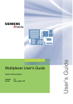
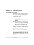
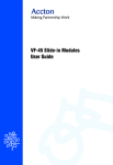
CheetahSwitch Workgroup-2027 Quick Installation Guide ES2027 E0298-R03 150185-101 Copyright © 1998 by Accton Technology Corporation. All rights reserved. No part of this document may be copied or reproduced in any form or by any means without the prior written consent of Accton Technology Corporation. CheetahSwitch Workgroup-2027 Accton makes no warranties with respect to this documentation and disclaims any implied warranties of merchantability, quality, or fitness for any particular purpose. The information in this document is subject to change without notice. Accton reserves the right to make revisions to this publication without obligation to notify any person or entity of any such changes. Smart Ethernet Switch with 24 10BASE-T (RJ-45) Ports, 1 AUI Port, and 2 Slots for Optional Fast Ethernet Uplink Modules International Headquarters No. 1 Creation Road III, Science-based Industrial Park Hsinchu 300, Taiwan, R.O.C. Phone: 886-3-5770-270 FAX: 886-3-5770-267 BBS: 886-3-5770-654 Internet: [email protected] USA Headquarters 1962 Zanker Road San Jose, CA 95112 Phone: 408-452-8900 FAX: 408-452-8988 BBS: 408-452-8828 FAST FAX: 408-452-8811 Accton is a trademark of Accton Technology Corporation. Other trademarks or brand names mentioned herein are trademarks or registered trademarks of their respective companies. ES2027 E0298-R03 150185-101 CheetahSwitch Workgroup-2027 Contents Quick Installation Guide Introduction Introduction 1 Package Contents 1 Description of Hardware 1 Mounting the Switch Stacking Switches on a Flat Surface Mounting Switches in a Rack 2 2 2 Connecting the Switch System Making a Connection via an MDI-X Station Port Making a Connection via the MDI Daisy-Chain Port Making a Connection via the AUI Port Connecting to an Uplink Module 2 3 3 4 4 Powering on the Switch 5 Verifying Port Status 6 Verifying System Operation 6 Configuring the Switch Displaying Port Utilization History Using the Configure Button Using the Console Program 7 7 7 7 Applications 9 Product Specifications 10 Troubleshooting Diagnosing Switch Indicators Power and Cooling Problems Installation Transmission Mode 11 11 11 11 11 Port and Cable Assignments 12 EMI Certification FCC Class A (USA) Class A (Canada Department of Communications) VCCI Class A Compliance (Japan) CE Mark Declaration of Conformance for EMI and Safety (EEC) 12 12 13 13 13 Safety Compliance 13 Warranty 14 The CheetahSwitch Workgroup-2027 switch is essential for moving large workgroups from the conventional 10Mbps shared Ethernet collision domain to multiple dedicated Ethernet segments. This switch delivers dedicated 10Mbps links to each attached LAN segment (independent collision domain) or attached PCs all with conventional cabling and adapters. It completely eliminates the bottlenecks of shared 10Mbps Ethernet networks by providing a wide bandwidth of up to 460 Mbps. This makes it ideal for increasing the throughput of interconnected Ethernet hubs or server farms. On top of all that, the AUI port and Fast Ethernet expansion modules make it easy to connect to a conventional Ethernet backbone or uplink to a Fast Ethernet network. Package Contents The Workgroup-2027 includes: CheetahSwitch Workgroup-2027 (Model No. ES2027) Ethernet switch with 24 RJ-45 ports, 1 AUI Port, and 2 expansion slots Four rubber foot pads Rack mount bracket kit AC power cord RS232 null-modem cable Description of Hardware This switch contains 24 RJ-45 Ethernet ports, 1 AUI port, and 2 slots for optional uplink modules for additional Fast Ethernet connections (100BASE-TX or 100BASE-FX). The transmission speed and mode for each port is shown in this table. Quick Installation Guide Advanced Reference Guide Owner registration card Ports Number 10BASE-T 1-24 AUI 25 100BASE-TX 26, 27 100BASE-FX 26, 27 S p eed (Mbps) 10 10 10, 1001 100 Duplex Mode 3 half, full half, full half, full, auto 2 half, full 1: auto -s e ns ing 2: auto -ne g o tiatio n (if als o s up p o rte d o n attac he d d e v ic e ) 3: s e t with c o nfig ure b utto n o r c o ns o le inte rfac e The following figure shows the components of the switch: 1 CheetahSwitch Workgroup-2027 Mounting the Switch This switch can be placed directly on your desktop, or mounted in a rack. Before you start installing the switch, make sure you can provide the right operating environment, including power requirements, sufficient physical space, and proximity to other network devices that are to be connected. Verify the following installation requirements: Power requirements: 100 to 240 VAC (± 10%) at 50 to 60 Hz (± 3Hz). The switch's power supply automatically adjusts to the input voltage level. The switch should be located in a cool dry place, with at least 10 cm. (4 in.) of space at the front and back for ventilation. Place the switch out of direct sunlight, and away from heat sources or areas with a high amount of electromagnetic interference. If you intend to mount the switch in a rack, make sure you have all the necessary mounting screws, brackets, bolts and nuts, and the right tools. Check if network cables and connectors needed for installation are available. Stacking Switches on a Flat Surface The CheetahSwitch can be stacked anywhere there is a enough flat space, such as on a table or desktop. 1. Stick the self-adhesive rubber foot pads (that come with this package) on each of the 4 concave spaces located on the bottom of the first switch. 2. Place the first switch on a firm flat surface where you want to install the stack. 3. Repeat step 1 for each switch before stacking them. The rubber foot pads cushion the switch against shock/vibrations and provide space between each switch for ventilation. Mounting Switches in a Rack Please comply with the following instructions to ensure that your switch is securely mounted in the rack. 1. Use a standard EIA 19-inch rack. 2. Use the brackets and screws supplied in the rack mounting kit. 3. Use a cross-head screwdriver to attach the brackets to the side of the switch. 4. Position the switch in the rack by lining up the holes in the brackets with the appropriate holes on the rack, and then use the supplied screws to mount the switch in the rack. Connecting the Switch System The CheetahSwitch has 24 RJ-45 ports and one AUI port that support connection to standard 10 Mbps Ethernet. It also has two slots for installing optional 100BASE-TX or 100BASE-FX Fast Ethernet Uplink Modules. All ports support full or half-duplex operation. The transmission mode for the 10BASE-T, AUI and 100BASE-FX ports must be manually configured using the configure button or console interface. (See "Configuring the Switch" on page 7.) The transmission mode can be set for the 100BASE-TX ports using auto-negotiation (if also supported by the attached device). However, if the devices attached to 2 Quick Installation Guide these ports do not support auto-negotiation, you can manually configure the port to match the transmission mode used by the attached device. You can also set the switching mode for any of the switch's ports to cut-through or store-and-forward using the console interface. (See Using the Console Program on page 7.) Making a Connection via an MDI-X Station Port You can connect any RJ-45 (MDI-X) station port on the switch to any device that uses a standard network interface such as a workstation or server, or to a network interconnection device such as a bridge or router (depending on the port type implemented on that device). 1. Prepare the devices you wish to network. Make sure you have installed 10BASE-T or 100BASE-TX network interface cards for connecting to the switch's RJ-45 (MDI-X) station ports. You also need to prepare straight-through shielded or unshielded twisted-pair cables with RJ-45 plugs at both ends. Use 100W Category 3, 4 or 5 cable for standard 10 Mbps Ethernet connections, or 100W Category 5 cable for 100 Mbps Fast Ethernet connections. 2. Connect one end of the cable to the RJ-45 port of the network interface card, and the other end to any available (MDI-X) station port on the switch. RJ-45 Ports 1 - 24 support 10 Mbps Ethernet connections (in addition to the AUI Port). If you ordered the 100BASE-TX uplink module, then you can also attach the switch to a 100 Mbps Fast Ethernet device. When inserting an RJ-45 plug, be sure the tab on the plug clicks into position to ensure that it is properly seated. Using the switch in a stand-alone configuration, you can network up to 27 end nodes. I Do not plug a phone jack connector into any RJ-45 port. This may damage the switch. Instead, use only twisted-pair cables with RJ-45 connectors that conform with FCC standards. Notes: 1. Make sure each twisted-pair cable does not exceed 100 meters (328 feet). 2. We advise using Category 5 cable for all network connections to avoid any confusion or inconvenience in the future when you upgrade attached devices to Fast Ethernet. Making a Connection via the MDI Daisy-Chain Port 1. To make a direct connection to another compatible switch or repeater hub, connect any RJ-45 (MDI-X) port on the switch to an MDI daisy-chain port on the other device. If you have a 100BASE-TX uplink module installed, then you can link to another switch or hub by running a cable from MDI-X to MDI ports on either device. (See "Connecting to an Uplink Module" on page 4.) 2. Prepare straight-through shielded or unshielded twisted-pair cables with RJ-45 plugs at both ends. Use 100W Category 3, 4 or 5 cable for standard 10 Mbps Ethernet connections, or 100W Category 5 cable for 100 Mbps Fast Ethernet connections. When inserting an RJ-45 plug, be sure the tab on the plug clicks into position to ensure that it is properly seated. Notes: 1. Make sure each twisted-pair cable does not exceed 100 meters (328 feet). 2. To connect to another switch or hub, you may also attach to (MDI-X) station ports at both ends if you use crossover cabling. 3. To achieve best performance when cascading switches, group devices or segments that communicate most frequently on the same switch, and reserve the Fast Ethernet uplinks for connecting to the larger network. 3 CheetahSwitch Workgroup-2027 Quick Installation Guide Restrictions on Cascade Length - Because the CheetahSwitch breaks up the path for connected devices into separate collision domains, it has no restrictions on cascade length. Therefore, when cascading devices other than this switch, do not include it or any connected cabling in your calculations for cascade length. The 100BASE-TX Uplink Module can set the transmission mode to full or half duplex via auto-negotiation. However if the attached device does not support autonegotiation, you can manually configure the connected port to half or full duplex using the configure button or console interface. (See "Configuring the Switch" on page 7.) I The uplink modules are not hot-swappable. Be sure you power off the switch before installing any of these modules. Installing an Uplink Module - You can install an uplink module as described below: Making a Connection via the AUI Port The AUI port is used for connection to the following 10 Mbps media types: Thin Ethernet (10BASE2) Thick Ethernet (10BASE5) Remote fiber optic link (10BASE-F) Thin Ethernet - Attach a BNC transceiver to the AUI port and plug the BNC T-type connector into a BNC port on the transceiver. When connecting two devices via BNC ports, there should be at least 0.5 meters (1.64 feet) of coaxial cable between the two BNC ports. A thin Ethernet coaxial cable segment can be extended up to 185 meters (607 feet) and can link up to 30 nodes. If the unit is at the terminal end of a trunk segment, connect a 50W terminator to the open end of the "T" connector. Note: Thin Ethernet only supports half-duplex communications. Thick Ethernet - Attach an AUI to 10BASE5 transceiver to the thick Ethernet trunk, and then run an AUI drop cable (with 15-pin D-type connectors on both ends) between the AUI port on the switch and the transceiver. Note that the maximum length of an AUI drop cable is 50 meters (164 feet). A thick Ethernet segment can be extended up to 500 meters (1640 feet) and can link up to 100 nodes. Note: Thick Ethernet only supports half-duplex communications. Fiber Optic - If you plan to use the AUI port for connecting fiber optic cable, attach a fiber optic transceiver (MAU) to the AUI port, and then connect the transceiver to the remote device. Note that 10 Mbps fiber can be extended up to two kilometers (1.24 miles), regardless of whether you are running the link at half or full duplex. Note: Your fiber optic transceiver may or may not support full-duplex communication, depending on the manufacturer. Connecting to an Uplink Module Additional network expansion can be achieved by inserting an optional 100BASE-TX or 100BASE-FX Uplink Module into either of the slots on the front panel. These Fast Ethernet modules act as a two-port switch (i.e., for external connection and for interfacing with the internal switching hardware). The 100BASE-TX module supports connection to either 10 Mbps Ethernet or 100 Mbps Fast Ethernet by automatically adjusting to the transmission speed of the attached device. It provides both RJ-45 MDI-X and MDI ports to simplify connection to endnode devices with a standard Ethernet interface (using the MDI-X port) or to another compatible switch or hub (using an MDI to MDI-X connection). Both SC and ST type modules are provided for 100BASE-FX. These modules run at 100 Mbps. Using either of these fiber modules, you can run a fiber optic link up to two kilometers (1.24 miles) when using full duplex, or up to 412 meters (0.25 miles) with half duplex. 4 1. Disconnect power to the switch. 2. Remove the face plate on the expansion slot (or a previously installed uplink module) by removing the two screws with a cross-head (Phillips) screwdriver. 3. Before opening the package that contains the uplink module, touch the bag to the switch casing to discharge any potential static electricity. 4. Remove the module from the anti-static shielded bag. 5. Holding the module level, gently push it all the way into the expansion slot, ensuring that it firmly engages with the connector. 6. If you are sure the module is properly mated with the connector, replace the retainer screws to secure the module in the expansion slot. 7. Run corresponding media type between the uplink module and the target device. Connecting Twisted-pair Cabling - If you will be using the 100BASE-TX module, prepare Category 5 straight-through twisted-pair cable with RJ-45 plugs at both ends. When connecting the module directly to an end-node device (e.g., a workstation or file server), a bridge or router, run cable from the MDI-X port on the uplink module to the target device. However, when connecting the module to a compatible switch or hub, connect one end of the cable to the MDI port on the uplink module, and the other end to an MDI-X port on the target device (or vice versa). When inserting an RJ-45 plug, be sure the tab on the plug clicks into position to ensure that it is properly seated. Note that as a general rule, the length of any twisted-pair cable should not exceed 100 meters (328 feet). Connecting Fiber Optic Cabling - If you are using a 100BASE-FX module, prepare fiber optic cable with SC or ST connectors at both ends. When connecting the module directly to an end-node device (e.g., a workstation or file server), run cable from the Rx (Tx) port on the module to the Tx (Rx) port on the target device. When inserting the cable, be sure the tab on the plug clicks into position to ensure that it is properly seated. Note that as a general rule, the length of fiber optic cable should not exceed 2 kilometers (1.24 miles) when the link is operated at full duplex or 412 meters (0.25 miles) for half duplex. Powering on the Switch 1. Plug the power cord into the power socket at the rear of the switch, and the other end into a power outlet. 2. Check the LED marked Power on the front panel to see if it is on. The unit will automatically select the setting that matches the connected input voltage. Therefore, no additional adjustments are necessary when connecting it to any input voltage within the range marked on the rear panel. 3. The switch performs a self-diagnostic test upon power-on. (Note that this test takes about 15 seconds to complete.) Note: The unit supports a "hot remove" feature which permits you to connect/ disconnect cables without powering off the switch and without disrupting the operation of the devices attached to the switch. 5 CheetahSwitch Workgroup-2027 Quick Installation Guide Verifying Port Status Configuring the Switch Check each connection by viewing the port status indicators shown in the following figure and table. The transmission mode for all ports must be set to the same mode used by the connected device. Ports 1 - 25 and the 100BASE-FX Uplink Module must be manually configured; but the system can use auto-negotiation to determine the transmission mode for the 100BASE-TX Uplink Module. However, if any device connected to this module does not support auto-negotiation, and a link cannot be established using half duplex (i.e., the last state tested by auto-negotiation), then you must manually set the transmission mode for the concerned port to half or full duplex using the configure button or console configuration program. Notes: 1. Full duplex can only be used for a dedicated link. When connecting to a shared collision domain (e.g., a repeater hub) be sure the transmission mode is set for half duplex. 2. This switch uses the NWays standard for auto-negotiation. If you connect a terminal or PC to the console port on the back of the switch, then you can perform the following tasks: LED Po we r Diag no s tic Co ns o le COL State On On On Flas hing FDX Link / Ac t On On Flas hing On 1001 I ndi cati on Switc h is re c e iv ing p o we r. Switc h is running d iag no s tic p ro g ram. Mo nito r o r o the r d e v ic e is c o nne c te d to the c o ns o le p o rt. Two o r mo re d e v ic e s atte mp te d to trans mit d ata at the s ame time . (No rmal s ituatio n und e r Ethe rne t CSMA/ CD. ) Co mmunic atio ns hav e b e e n s e t to full-d up le x mo d e . Po rt has e s tab lis he d a v alid ne two rk c o nne c tio n. Traffic is trav e rs ing the p o rt. Co mmunic atio ns hav e b e e n s e t to 100 Mb p s . 1 - This ind ic ato r o nly ap p e ars o n the 100BASE-TX up link mo d ule . Verifying System Operation Verify that all attached devices have a valid connection. The switch monitors the link status for each port. If any device is properly connected to the switch and transmitting a link beat signal, the Link indicator will light up for the corresponding port. If the Link indicator fails to light when you connect a device to the switch, check the following items: Both sides of each connection must use the same transmission mode (i.e., half or full duplex). If a device is connected to the 10BASE-T or 100BASE-FX ports, then you must manually set the transmission mode using the on-board configuration program. (See "Configuring the Switch" on page 7.) If any device connected to the 100BASE-TX ports does not support auto-negotiation and cannot operate at half duplex (i.e., the system default when auto-negotiation fails), then you must also manually set the transmission mode using the configure button or on-board configuration program. Be sure all network cables and connectors are properly attached to the connected device and the switch. See if your cable is functioning properly by using it for another port and attached device that displays valid indications when connected to the network. Verify that you have not exceeded the specified limits for any attached media type as summarized in the following table: Medi a Type Twis te d Pair Thin Ethe rne t Thic k Ethe rne t Fib e r Op tic (10 Mb p s ) Fib e r Op tic (100 Mb p s ) Max Length 100 me te rs (328 fe e t) 185 me te rs (607 fe e t) 500 me te rs (0. 3 mile s ) 2000 me te rs (1. 24 mile s ) half d up le x : 412 m (0. 25 mile s ) full d up le x : 2000 m (1. 24 mile s ) 1 - Minimum d is tanc e b e twe e n no d e s . 2 - Max imum le ng th o f d ro p c ab le fro m AUI p o rt to trans c e iv e r. (0. 5 me te rs = 1. 64 fe e t; 50 me te rs = 164 fe e t) 6 Max Nodes Other 1000 30 0. 5 me te rs 1 500 50 me te rs 2 link p air link p air Enable/disable any port Set the communication mode for any port Set the switching mode to cut-through or store-and-forward Restart the system Displaying Port Utilization History The switch can display a history of LAN bandwidth utilization for any port (selected with the configure button). A graph showing the percentage of valid data (compared to available bandwidth) that has passed through the selected port over the past 20 seconds is shown on the LED array located to the right of the displayed port number. Just use a short press (1 second) on the configure button to scan through the port numbers and display the current ports utilization. Using the Configure Button The switch can set the transmission mode for any port (selected with the configure button). Use a short press (1second) to scan through the port numbers. When the required port number is displayed, use a long press (3 seconds) to display the current communication mode on the LED matrix to the right of the port number. To change modes, use a short press to scan through the available options. Ports 1 25 support half and full duplex; while Ports 26 - 27 support 10 or 100 Mbps, as well as half or full duplex and auto-negotiation (if the attached also supports this feature). When the required mode is displayed on the front panel, use another long press to enable your selection. Notes: 1. The configuration options for the 10 Mbps ports includes half duplex, full duplex or auto-negotiation. 2. Options for the optional 100 Mbps uplink ports cover both speed and mode, as well as full auto-negotiation. Using the Console Program Establishing a Connection - Attach a VT100 compatible terminal or a PC running a terminal emulation program to the DB9 serial port on the back of the switch. Use the RS232 null-modem cable provided with this package, or use a null modem connection that complies with the wiring assignments shown on page 11. When attaching to a PC, set terminal emulation type to VT100, specify the port used by your PC (i.e., COM 1~4), and then set communications to 8 data bits, 1 stop bit, no parity, and 9600 bps. Also be sure to set flow control to "none." 7 CheetahSwitch Workgroup-2027 If this is your first time to log into the configuration program, then the default password will still be null. Just enter a carriage return for the "Login" and "Password" fields to open the Main Menu as shown below. ACCTON CheetahSwitch Workgroup-2027 V1.00 05-04-97 Main Menu --------Port Configuration ... Password Configuration ... Restart System Factory Reset Exit Configure port setting. <Enter> to confirm. Note: Input options for the currently selected item are displayed in the highlighted area at the bottom of the console screen. Configuring the Ports - You can use the console program to quickly view or modify the configuration of any port on the switch. Select "Port Configuration" from the Main Menu to open the following screen. (The system defaults are shown below.) ACCTON CheetahSwitch Workgroup-2027 V1.00 05-04-97 Port Configuration ==================================== Back to Previous Menu Port Enabled Duplex Fwd Mode ============================================= 1 YES Half St&Fwd 2 YES Half St&Fwd 3 YES Half St&Fwd 4 YES Half St&Fwd 5 YES Half St&Fwd 6 YES Half St&Fwd 7 YES Half St&Fwd 8 YES Half St&Fwd 9 YES Half St&Fwd Quick Installation Guide Factory Reset - Use this command to restore factory defaults and reboot the system. Logging Off the System - Use the Exit command to exit the configuration program and terminate communications with the switch for the current session. Applications This switch segments your network, significantly increasing both bandwidth and throughput. Any port on the switch can be attached to a hub (i.e., shared collision domain) or provide a dedicated link to a single network device (e.g., a workstation). When a port on the switch is connected to an Ethernet hub (i.e., a 10 or 100 Mbps repeater), the bandwidth provided by that port is shared by all the devices connected to the attached hub. However, when a port is connected to an end node or to a device that breaks up the collision domain (e.g., another switch, bridge or router), the attached device has access to the full bandwidth provided by that port. Bridging Functions - This switch provides fully transparent bridging functions which automatically learn node addresses, that are subsequently used to filter and forward all traffic based on the destination address. When traffic passes between devices attached to the same shared collision domain, those packets are filtered from the switch. But when traffic must be passed between unique segments (i.e., different ports on the switch), a temporary link is set up between the switch ports which need to pass this traffic (via high-bandwidth shared memory). Switching Functions - The scheme used to forward traffic to other ports can be configured to optimize system performance or to enhance data integrity by using cut-through or store-and-forward switching, respectively. Flexible Configuration - This switch is not only designed to segment your network, but also to provide a wide range of options in setting up network connections. It can be used as a simple stand-alone switch; or can be connected with standard repeater hubs, switches, or other network interconnection devices in various configurations. A sample configuration diagram is shown below. Next Page Back to previous menu. <Enter> to confirm, <Ctrl+Z> to back to Main Menu The functions provided by this screen are summarized in the following table: Field Description Enabled Allows you to disable a port due to abnormal behavior (e.g., excessive collisions), and then re-enable it after the problem has been resolved. You may also disable a port for security reasons. Ports 1 - 25 support full duplex and half duplex. (The default is Half.) Ports 26 - 27 support auto-negotiation, full and half duplex. (The default is Auto.) Sets the forwarding method to cut-through (CT), or store and forward (St&Fwd). Duplex Fwd Mode Setting a Password - If the switch is not in a secure location such as a wiring closet, you should define a user name and password. If you have not done so, select "Password Configuration" from the Main Menu and enter a password. Note that passwords can consist of up to 14 alphanumeric characters and are case sensitive. Restarting the System - Use the Restart command to reboot the system. 8 9 CheetahSwitch Workgroup-2027 Filtering Rate Forwarding Rate Product Specifications Base Unit Access Method Standards Conformance Communication Rate Communication Mode Media Supported Number of Ports Indicator Panel Dimensions Weight Input Power Power Consumption Heat Dissipation Temperature Humidity Certification Emissions Immunity Safety Uplink Modules 100BASE-TX Access Method Standards Conformance Communication Rate Communication Mode Media Supported Number of Ports Indicator Panel 100BASE-FX Access Method Standards Conformance Communication Rate Communication Mode Media Supported Number of Ports Indicator Panel Switching Criteria Network Bridging Function Switching Method Address Table Queue Buffer Address Resolution 10 Quick Installation Guide CSMA/CD, 10 Mbps IEEE 802.3 10BASE-T, AUI 10 Mbps on Ports 1 - 25 Ports 1-25: full or half duplex 10BASE-T - 100W Category 3,4,5 twisted-pair, 10BASE2 - thin Ethernet coaxial cable (AUI), 10BASE5 - thick Ethernet coaxial cable (AUI), 10BASE-F - SC/ST type multimode fiber (AUI) 24 10BASE-T ports and 1 AUI port LEDs for monitoring diagnostics, console connection, utilization, collision, communication mode, link, activity 440 x 305 x 63 mm (17.3 x 12 x 2.5 in) 4.75 kg (10.47 lb) Full range power input: 100 to 240V (±10%) 50 to 60 Hz (±3Hz) 75 Watts max. at 100 VAC and 240 VAC 256 BTU/hr 0 to 40°C (32 to 104°F) Standard Operating 5% to 95% (Noncondensing) CE Mark FCC Class A, VCCI Class A, CISPR Class A IEC 1000-4-2/3/4/6 UL, CSA, TÜV/GS CSMA/CD, 10 or 100 Mbps IEEE 802.3u 100BASE-TX 10 or 100 Mbps (manual or auto-detection) Full or half duplex (manual or auto-negotiation) 100BASE-TX 100W Cat 5 for 100 Mbps, or 100W Cat 3,4,5 for 10 Mbps 1 100BASE-TX RJ-45 port (MDI-X or MDI connection) Comprehensive array of LEDs for displaying port link, collision, activity, transmission speed and mode CSMA/CD, 100 Mbps IEEE 802.3u 100BASE-FX 100 Mbps Full or half duplex (manual) 50/125 mm or 62.5/125 mm multimode fiber 1 100BASE-FX SC or ST type port Comprehensive array of LEDs for displaying port link, collision, activity, transmission speed and mode filtering, forwarding and learning cut-through or store-and-forward 2K entries 8M shared memory via fast hashing scheme 14,880 pps at 10 Mbps, 148,800 pps at 100 Mbps 14,880 pps at 10 Mbps, 148,800 pps at 100 Mbps Management Support System Configuration Push-button configuration; on-board configuration via serial port, Telnet or remote modem link Troubleshooting Diagnosing Switch Indicators The switch can be easily monitored through panel indicators to assist the network manager in identifying problems. This section describes common problems you may encounter and possible solutions. Symptom: Link indicator does not light up (green) after making a connection. Cause: Network interface (e.g., a network adapter card on the attached device), network cable, or switch port is defective. Solution: Verify that the switch and attached device are powered on. Be sure the cable is plugged into both the switch and corresponding device. Verify that the proper cable type is used and its length does not exceed specified limits (100m or 328ft). Check the adapter on the attached device and cable connections for possible defects. Replace the defective adapter or cable if necessary. Symptom: Power indicator does not light up (green) after power on. Cause: Defective power outlet, power cord, or internal power supply. Solution: Check the power outlet by plugging in another device that is functioning properly. Check the power cord with another device. If these measures fail to resolve the problem, have the unit's power supply replaced by a qualified Accton distributor. Power and Cooling Problems If the Power indicator does not turn on when the power cord is plugged in, you may have a problem with the power outlet, power cord, or internal power supply as explained in the previous section. However, if the unit powers off after running for a while, check for loose power connections, power losses or surges at the power outlet, and verify that the fan on back of the unit is unobstructed and running prior to shutdown. If you still cannot isolate the problem, then the internal power supply may be defective. In this case, contact your Accton distributor for assistance. Installation Verify that all system components have been properly installed. If one or more components appear to be malfunctioning (e.g., the power cord or network cabling), test them in an alternate environment where you are sure that all the other components are functioning properly. Transmission Mode When you use Ports 1 - 25 or the 100BASE-FX port, verify that each port is set to the same transmission mode used by the attached device (i.e., half or full duplex). You can configure the ports using the configure button or console program as described in Configuring the Switch on page 7. When using the 100BASE-TX port, the switch can be configured to use auto-negotiation to set the transmission mode. However, if the attached device does not support auto-negotiation, then you must manually configure the port. 11 CheetahSwitch Workgroup-2027 Quick Installation Guide Port and Cable Assignments You may use unshielded twisted-pair (UTP) for RJ-45 connections - Category 3 or greater for 10 Mbps connections, and Category 5 for 100 Mbps connections. RJ-45 Port Description Class A (Canada Department of Communications) RJ-45 station ports (MDI-X) can be attached to any devices which use a standard network interface (e.g., a workstation, server, bridge or router). Similar networking devices (e.g., another switch or hub) can be cascaded by connecting any of the RJ-45 station ports on the switch to a daisy-chain port (MDI) on the other device. Use unshielded twisted-pair (UTP) or shielded twisted-pair (STP) cable for RJ-45 connections: 100W Category 3, 4 or 5 cable for 10 Mbps connections or 100W Category 5 cable for 100 Mbps connections. Also be sure that the length of any twisted-pair connection does not exceed 100 meters (328 feet). Assi gnment (Stati on Ports 1 - 24) 1 Inp ut Re c e iv e Data + 2 Inp ut Re c e iv e Data 3 Outp ut Trans mit Data + 6 Outp ut Trans mit Data 4, 5, 7, 8 No t Us e d Pi n Assi gnment (Dai sy-Chai n Port, other devi ce) Outp ut Trans mit Data + Outp ut Trans mit Data Inp ut Re c e iv e Data + Inp ut Re c e iv e Data No t Us e d Schematics for both straight and crossover twisted-pair cable are shown below. Strai ght-Through (Switc h) (Ad ap te r) 1 IRD+ 1 OTD+ 2 IRD2 OTD3 OTD+ 3 IRD+ 6 OTD6 IRD- (Switc h) 1 IRD+ 2 IRD3 OTD+ 6 OTD- Crossover (Switc h) 1 IRD+ 2 IRD3 OTD+ 6 OTD- AUI Port Description The AUI Port provides a media independent interface that can be attached to a thin Ethernet backbone (10BASE2), a thick Ethernet backbone (10BASE5), or to remote device using fiber optic cable (10BASE-F). Note that when using this port, you must first attach a transceiver (MAU) designed to interface with the selected media type, and then attach the cable to the transceiver. Pi n 1 2 3 4 5 6 9 10 11 12 13 14 7, 8 , 15 Assi gnment Co llis io n In Shie ld Co llis io n In + Data Out + Data In Shie ld Data In + DC Po we r Co mmo n Co llis io n In Data Out Data Out Shie ld Data In DC Po we r + Po we r Shie ld No Co nne c tio n This digital apparatus does not exceed the Class A limits for radio noise emissions from digital apparatus as set out in the interference-causing equipment standard entitled "Digital Apparatus", ICES-003 of the Department of Communications. Cet appareil numérique respecte les limites de bruits radioélectriques applicables aux appareils numériques de Classe A prescrites dans la norme sur le matériel brouilleur: "Appareils Numérques", NMB-003 édictée par le ministère des Communications. VCCI Class A Compliance (Japan) CE Mark Declaration of Conformance for EMI and Safety (EEC) This is to certify that this product complies with ISO/IEC Guide 22 and EN45014. It conforms to the following specifications: EMC: EN55022(1988)/CISPR-22(1985) EN60555-2(1995) EN60555-3 IEC1000-4-2(1995) IEC1000-4-3(1995) IEC1000-4-4(1995) IEC 1000-4-6(1995) Warning: This equipment generates, uses, and can radiate radio frequency energy and, if not installed and used in accordance with the instruction manual, may cause interference to radio communications. It has been tested and found to comply with the limits for a Class A digital device pursuant to Subpart B of Part 15 of FCC Rules, which are designed to provide reasonable protection against such interference when operated in a commercial environment. Operation of this equipment in a residential area is likely to cause interference, in which case the user, at his own expense, will be required to take whatever measures are required to correct the interference. 12 4kV CD, 8kV AD 3V/m 1kV - (power line), 0.5kV - (signal line) 3Vrms This product complies with the requirements of the Low Voltage Directive 73/23/EEC and the EMC Directive 89/336/EEC. Warning! Do not plug a phone jack connector in the RJ-45 port. This may damage this device. Les raccordeurs ne sont pas utilisé pour le système téléphonique! Safety Compliance Underwriters Laboratories Inc. (USA) Important! Before making connections, make sure you have the correct Cord Set. Check it (read the label on the cable) against the following specification list. Voltage 120 Vo lts EMI Certification FCC Class A (USA) class A class A 240 Vo lts (No rth Ame ric a) 240 Vo lts (Euro p e o nly ) C ord Set Specifications UL Lis te d / CSA Ce rtifie d Co rd Se t Minimum 18 AWG; ty p e SVT o r SJ T thre e c o nd uc to r c o rd Max imum le ng th o f 15 fe e t Paralle l b lad e , g ro und ing ty p e attac hme nt p lug rate d 15A, 125V UL Lis te d / CSA Ce rtifie d Co rd Se t Minimum 18 AWG; ty p e SVT o r SJ T thre e c o nd uc to r c o rd Max imum le ng th o f 15 fe e t Tand e m b lad e , g ro und ing ty p e attac hme nt p lug rate d 15A, 125V Co rd Se t with H05VV-F c o rd hav ing thre e c o nd uc to rs with minimum d iame te r o f 0. 75 mm² IEC-320 re c e p tac le ; male p lug rate d 10A, 250V 13 CheetahSwitch Workgroup-2027 Quick Installation Guide Wichtige Sicherheitshinweise (Germany) 1. Bitte lesen Sie diese Hinweise sorgfältig durch. 2. Heben Sie diese Anleitung für den späteren Gebrauch auf. 3. Vor jedem Reinigen ist das Gerät vom Stromnetz zu trennen. Verwenden Sie keine Flüssigoder Aerosolreiniger. Am besten eignet sich ein angefeuchtetes Tuch zur Reinigung. 4. Die Netzanschlu ßsteckdose soll nahe dem Gerät angebracht und leicht zugänglich sein. 5. Das Gerät ist vor Feuchtigkeit zu schützen. 6. Bei der Aufstellung des Gerätes ist auf sicheren Stand zu achten. Ein Kippen oder Fallen könnte Beschädigungen hervorrufen. 7. Die Belüftungsöffnungen dienen der Luftzirkulation, die das Gerät vor Überhitzung schützt. Sorgen Sie dafür, daß diese Öffnungen nicht abgedeckt werden. 8. Beachten Sie beim Anschluß an das Stromnetz die Anschlußwerte. 9. Verlegen Sie die Netzanschlußleitung so, daß niemand darüber fallen kann. Es sollte auch nichts auf der Leitung abgestellt werden. 10. Alle Hinweise und Warnungen, die sich am Gerät befinden, sind zu beachten. 11. Wird das Gerät über einen längeren Zeitraum nicht benutzt, sollten Sie es vom Stromnetz trennen. Somit wird im Falle einer Überspannung eine Beschädigung vermieden. 12. Durch die Lüftungsöffnungen dürfen niemals Gegenstände oder Flüssigkeiten in das Gerät gelangen. Dies könnte einen Brand bzw. elektrischen Schlag auslösen. 13. Öffnen sie niemals das Gerät. Das Gerät darf aus Gründen der elektrischen Sicherheit nur von authorisiertem Servicepersonal geöffnet werden. 14. Wenn folgende Situationen auftreten ist das Gerät vom Stromnetz zu trennen und von einer qualifizierten Servicestelle zu überprüfen: a. Netzkabel oder Netzstecker sind beschädigt. b. Flüssigkeit ist in das Gerät eingedrungen. c. Das Gerät war Feuchtigkeit ausgesetzt. d. Wenn das Gerät nicht der Bedienungsanleitung entsprechend funktioniert oder Sie mit Hilfe dieser Anleitung keine Verbesserung erzielen. e. Das Gerät ist gefallen und/oder das Gehäuse ist beschädigt. f. Wenn das Gerät deutliche Anzeichen eines Defektes aufweist. Der arbeitsplatzbezogene Schalldruckpegel nach DIN 45 635 Teil 1000 beträgt 70dB(A) oder weniger. Warranty Accton warrants to the original owner that the product delivered in this package will be free from defects in material and workmanship for the lifetime of the product. For the warranty to apply, you must register your purchase by returning the registration card indicating the date of purchase and including proof of purchase. There will be a minimal charge to replace consumable components, such as fuses, power transformers, and mechanical cooling devices. The warranty does not cover the product if it is damaged in the process of being installed. THE ABOVE WARRANTY IS IN LIEU OF ANY OTHER WARRANTY, WHETHER EXPRESS, IMPLIED OR STATUTORY, INCLUDING BUT NOT LIMITED TO ANY WARRANTY OF MERCHANTABILITY, FITNESS FOR A PARTICULAR PURPOSE, OR ANY WARRANTY ARISING OUT OF ANY PROPOSAL, SPECIFICATION OR SAMPLE. ACCTON SHALL NOT BE LIABLE FOR INCIDENTAL OR CONSEQUENTIAL DAMAGES. ACCTON NEITHER ASSUMES NOR AUTHORIZES ANY PERSON TO ASSUME FOR IT ANY OTHER LIABILITY. 14 15