1
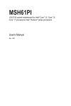
EMX-CDV Intel® Atom™ EMX-CDV Mini ITX Motherboard with Intel® ICH10R Chipset Quick Installation Guide 1st Ed – 20 September 2012 Copyright Notice Copyright 2012 Avalue Technology Inc., ALL RIGHTS RESERVED. Part No. E2017XCDV00R EMX-CDV Content 1. Getting Started ............................................................................................................ 3 1.1 Safety Precautions .................................................................................................... 3 1.2 Packing List ............................................................................................................... 3 2. Hardware Configuration ............................................................................................. 4 2.1 Product Overview ...................................................................................................... 5 2.2 Jumper and Connector List ....................................................................................... 6 2.3 Setting Jumpers & Connectors .................................................................................. 8 2.3.1 Serial Port 1 Setting - RS232/422/485 (JRS1, JRS2, JRS3, JRS4) .............................................. 8 2.3.2 Serial Port 1 Select - RS-232/422/485 (JCOM1) ........................................................................... 9 2.3.3 Serial Port 3 RI Pin Signal Select – Ring/+5V/+12V (JCOM3) .................................................... 10 2.3.4 Power Mode Select – AT or ATX (AT_CN) .................................................................................. 11 2.3.5 Clear CMOS (CLR_CMOS) .......................................................................................................... 11 2.3.6 System Fan Connector (SYS_FAN) ............................................................................................. 12 2.3.7 Serial Port 3 Connector (COM3) .................................................................................................. 12 2.3.8 Serial Port 4 Connector (COM4) .................................................................................................. 13 2.3.9 Serial Port 5 Connector (COM5) .................................................................................................. 13 2.3.10 Serial Port 6 Connector (COM6) ................................................................................................ 14 2.3.11 LVDS Connector (LVDS) ........................................................................................................... 14 2.3.12 LCD Inverter Connector (BKL_CN) ........................................................................................... 15 2.3.13 Front Panel Connector (F_PANEL) ........................................................................................... 15 2.3.14 Front Panel Audio Connector (F_AUDIO).................................................................................. 16 2.3.14.1 Signal Description – Audio connector (F_AUDIO) ....................................................................... 16 2.3.15 Audio Amplifier Connector (SPK_OUT) ..................................................................................... 17 2.3.16 SATA Power (SATAPW_1) ........................................................................................................ 17 2.3.17 SATA Power (SATAPW_2) ........................................................................................................ 18 2.3.18 USB Connector (F_USB1) ......................................................................................................... 18 2.3.19 USB Connector (F_USB2) ......................................................................................................... 19 2.3.20 GPIO Connector (GPIO_CNT) ................................................................................................... 19 2.3.21 Low Pin Count Connector (LPC) ................................................................................................ 20 2 EMX-CDV Quick Installation Guide Quick Installation Guide 1. Getting Started 1.1 Safety Precautions Warning! Always completely disconnect the power cord from your chassis whenever you work with the hardware. Do not make connections while the power is on. Sensitive electronic components can be damaged by sudden power surges. Only experienced electronics personnel should open the PC chassis. Caution! Always ground yourself to remove any static charge before touching the CPU card. Modern electronic devices are very sensitive to static electric charges. As a safety precaution, use a grounding wrist strap at all times. Place all electronic components in a static-dissipative surface or static-shielded bag when they are not in the chassis. 1.2 Packing List Before you begin installing your single board, please make sure that the following materials have been shipped: 1 x EMX-CDV Mini-ITX Motherboard 1 x CD-ROM contains OS drivers/QIG/User’s Manual 1 x COM cable 2 x SATA cable 2 x SATA Power Cable 1 x DC Jack to ATX Power Cable 1 x I/O shield EMX-CDV Quick Installation Guide 3 EMX-CDV 2. Hardware Configuration 4 EMX-CDV Quick Installation Guide Quick Installation Guide 2.1 Product Overview EMX-CDV Quick Installation Guide 5 EMX-CDV 2.2 Jumper and Connector List You can configure your board to match the needs of your application by setting jumpers. A jumper is the simplest kind of electric switch. It consists of two metal pins and a small metal clip (often protected by a plastic cover) that slides over the pins to connect them. To “close” a jumper you connect the pins with the clip. To “open” a jumper you remove the clip. Sometimes a jumper will have three pins, labeled 1, 2, and 3. In this case, you would connect either two pins. The jumper settings are schematically depicted in this manual as follows: A pair of needle-nose pliers may be helpful when working with jumpers. Connectors on the board are linked to external devices such as hard disk drives, a keyboard, or floppy drives. In addition, the board has a number of jumpers that allow you to configure your system to suit your application. If you have any doubts about the best hardware configuration for your application, contact your local distributor or sales representative before you make any changes. The following tables list the function of each of the board's jumpers and connectors. Jumpers Label Function Note JRS1/2/3/4 Serial Port 1 Setting – RS232/422/485 3 x 1 header, pitch 2.00 mm JCOM1 Serial Port 1 Select - RS-232/422/485 3 x 2 header, pitch 2.00 mm JCOM3 Serial Port 3 RI Pin Signal Select – Ring/+5V/+12V 3 x 2 header, pitch 2.54 mm AT_CN Power Mode Select – AT or ATX 3 x 1 header, pitch 2.00 mm CLR_CMOS Clear CMOS 2 x 1 header, pitch 2.54 mm Label Function Note ATX_12V ATX 4pin DC12 SODIMM1 DIMM Slot DDR3 Connectors 6 EMX-CDV Quick Installation Guide Quick Installation Guide SODIMM2 DIMM Slot DDR3 SYS_FAN System Fan Connector 4 x 1 wafer, pitch 2.54mm COM1 Serial Port 1 Connector D-sub 9-pin, male COM2 Serial Port 2 Connector D-sub 9-pin, male COM3 Serial Port 3 Connector 5 x 2 wafer, pitch 2.00 mm COM4 Serial Port 4 Connector 5 x 2 wafer, pitch 2.00 mm COM5 Serial Port 5 Connector 5 x 2 wafer, pitch 2.00 mm COM6 Serial Port 6 Connector 5 x 2 wafer, pitch 2.00 mm LVDS LVDS Connector 20 x 2 wafer, pitch 1.25mm BKL_CN LCD Inverter Connector 5 x 1 wafer, pitch 2.00mm USB_LAN1 USB+LAN1 USB_LAN2 USB+LAN2 KB_MS PS/2 Keyboard & Mouse Connector HDMI HDMI VGA VGA Connector Min_PCIE1 Mini PCIE Connector 1 Min_PCIE2 Mini PCIE Connector 2 (co-lay mSATA) AUDIO AUDIO Line-In/Line-Out/Mic-In PCI1 PCI Slot F_AUDIO Front Panel Audio Connector 5 x 2 wafer, pitch 2.00 mm SPK_OUT Audio Amplifier Connector 4 x 1 wafer, pitch 2.00 mm SATAII 1/2/3/4 Serial ATA Connector 1/2/3/4 SATAPW_1 SATA Power 1 4 x 1 wafer, pitch 2.54mm SATAPW_2 SATA Power 2 (Option) 4 x 1 wafer, pitch 2.54mm F_USB1 USB Connector 1 5 x 2 wafer, pitch 2.00 mm F_USB2 USB Connector 2 5 x 1 wafer, pitch 2.00 mm GPIO_CNT GPIO Connector 6 x 2 wafer, pitch 2.00 mm LPC Low Pin Count Connector 7 x 2 wafer, pitch 2.00 mm F_PANEL Front Panel Connector 6 x 2 wafer, pitch 2.00 mm DC_IN DC Power-In Connector EMX-CDV Quick Installation Guide 7 EMX-CDV 2.3 Setting Jumpers & Connectors 2.3.1 Serial Port 1 Setting - RS232/422/485 (JRS1, JRS2, JRS3, JRS4) RS232* JRS3 JRS1 JRS4 JRS2 RS422/RS485 RS422/485 Pin Mapping * Default 8 EMX-CDV Quick Installation Guide Pin RS-232 RS-485 RS-422 1 DCD TXD- TXD- 2 RXD TXD+ TXD+ 3 TXD RXD+ 4 DTR RXD- 5 GND 6 DSR 7 RTS 8 CTS 9 RI GND GND Quick Installation Guide 2.3.2 Serial Port 1 Select - RS-232/422/485 (JCOM1) RS232* RS485 RS422 * Default Signal PIN PIN Signal RXD232 1 2 RXD1 RXD422 3 4 RXD1 RXD485 5 6 RXD1 EMX-CDV Quick Installation Guide 9 EMX-CDV 2.3.3 Serial Port 3 RI Pin Signal Select – Ring/+5V/+12V (JCOM3) +5V +12V Ring* * Default Signal 10 EMX-CDV Quick Installation Guide PIN PIN Signal VCC 1 2 RI3-/5V/12V NRI3- 3 4 RI3-/5V/12V +12V 5 6 RI3-/5V/12V Quick Installation Guide 2.3.4 Power Mode Select – AT or ATX (AT_CN) ATX * AT * Default Signal PIN AT_PWR_F_BTN# 1 PWR_F_BTN# 2 NC 3 2.3.5 Clear CMOS (CLR_CMOS) Normal * Clear * Default Signal PIN -RTCRST 1 GND 2 EMX-CDV Quick Installation Guide 11 EMX-CDV 2.3.6 2.3.7 System Fan Connector (SYS_FAN) Signal PIN PWM Input 4 FANIO2 3 +12V 2 GND 1 Serial Port 3 Connector (COM3) Signal 12 EMX-CDV Quick Installation Guide PIN PIN Signal NC 9 10 RI3-/5V/12V NCTS3- 7 8 NRTS3- NDSR3- 5 6 GND NDTR3- 3 4 NTXD3- NRXD3- 1 2 NDCD3- Quick Installation Guide 2.3.8 Serial Port 4 Connector (COM4) Signal 2.3.9 PIN PIN Signal NC 9 10 NRI4- NCTS4- 7 8 NRTS4- NDSR4- 5 6 GND NDTR4- 3 4 NTXD4- NRXD4- 1 2 NDCD4- Serial Port 5 Connector (COM5) Signal PIN PIN Signal NC 9 10 NRI5- NCTS5- 7 8 NRTS5- NDSR5- 5 6 GND NDTR5- 3 4 NTXD5- NRXD5- 1 2 NDCD5- EMX-CDV Quick Installation Guide 13 EMX-CDV 2.3.10 Serial Port 6 Connector (COM6) Signal 2.3.11 PIN PIN Signal NC 9 10 NRI6- NCTS6- 7 8 NRTS6- NDSR6- 5 6 GND NDTR6- 3 4 NTXD6- NRXD6- 1 2 NDCD6- Signal PIN PIN Signal VCC3 1 2 VCC VCC3 3 4 VCC SCL1 5 6 SDA1 GND 7 8 GND +RXO1_C 9 10 +RXO0_C -RXO1_C 11 12 -RXO0_C GND 13 14 GND +RXO3_C 15 16 +RXO2_C -RXO3_C GND 17 18 19 20 -RXO2_C GND +RXE1_C 21 22 +RXE0_C -RXE1_C GND 23 24 25 26 -RXE0_C GND +RXE3_C 27 28 +RXE2_C -RXE3_C GND 29 30 31 32 -RXE2_C GND +RXECLKE_C 33 34 +RXECLKO_C -RXECLKE_C GND 35 36 37 38 -RXECLKO_C GND +12V 39 40 +12V LVDS Connector (LVDS) 14 EMX-CDV Quick Installation Guide Quick Installation Guide 2.3.12 2.3.13 LCD Inverter Connector (BKL_CN) Signal PIN +12V 5 GND 4 BKLTEN 3 BKLTCTL 2 VCC 1 Front Panel Connector (F_PANEL) Signal Standby PIN PIN Signal Standby 11 12 -INTRUDER 9 10 GND SATA LED- 7 8 SATA LED+ Power LED+ 5 6 3 4 1 2 Power LED+ System Reset# Power Button# Power LED- Power LED GND RST GND Power Button GND EMX-CDV Quick Installation Guide 15 EMX-CDV 2.3.14 Front Panel Audio Connector (F_AUDIO) Signal PIN PIN GND 2 1 MIC_L -ACZ_DET 4 3 MIC_R SRTN1 6 5 HPOUT_R_H NC 8 7 FAUDIO_JD SRTN2 10 9 HPOUT_L_H 2.3.14.1 Signal Description – Audio connector (F_AUDIO) Signal Signal Description MIC_L Front panel microphone left channel MIC_R Front panel microphone right channel -ACZ_DET Active low when an Intel® HD Audio dongle is connected HPOUT_R_H Front panel headphone right channel HPOUT_L_H Front panel headphone left channel SRTN1 Jack detection for front panel microphone SRTN2 Jack detection for front panel headphone FAUDIO_JD Front panel jack detect 16 EMX-CDV Quick Installation Guide Signal Quick Installation Guide 2.3.15 2.3.16 Audio Amplifier Connector (SPK_OUT) Signal PIN OUT_R+ 1 OUT_R- 2 OUT_L- 3 OUT_L+ 4 Signal PIN +12V 1 GND 2 GND 3 VCC 4 SATA Power (SATAPW_1) EMX-CDV Quick Installation Guide 17 EMX-CDV 2.3.17 2.3.18 SATA Power (SATAPW_2) Signal PIN +12V 1 GND 2 GND 3 VCC 4 USB Connector (F_USB1) Signal 18 EMX-CDV Quick Installation Guide PIN PIN Signal USB Power 2 1 USB Power USBP0- 4 3 USBP1- USBP0+ 6 5 USBP1+ GND 8 7 GND GND 10 9 GND Quick Installation Guide 2.3.19 2.3.20 USB Connector (F_USB2) Signal PIN GND 1 GND 2 USBP2+ 3 USBP2- 4 USB Power 5 GPIO Connector (GPIO_CNT) Signal PIN PIN Signal VCC 11 12 GND SMBCLK 9 10 SMBDATA SOGP0_4 7 8 SOGP1_4 SOGP0_3 5 6 SOGP1_3 SOGP0_2 3 4 SOGP1_2 SOGP0_1 1 2 SOGP1_1 EMX-CDV Quick Installation Guide 19 EMX-CDV 2.3.21 Low Pin Count Connector (LPC) Signal 20 EMX-CDV Quick Installation Guide PIN PIN Signal -LDRQ1 13 14 5VDUAL GND 11 12 VCC GND 9 10 SERIRQ LPC_CLK 7 8 LAD3 -LFRAME 5 6 LAD2 -PFMRST 3 4 LAD1 VCC3 1 2 LAD0