1
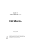
EAX-Q77 Intel® Q77 with Core™ i7/ i5/ i3 ATX Motherboard User’s Manual 3rd Ed – 12 March 2014 Part No: E2047AQ7702R EAX-Q77 User’s Manual FCC Statement THIS DEVICE COMPLIES WITH PART 15 FCC RULES. OPERATION IS SUBJECT TO THE FOLLOWING TWO CONDITIONS: (1) THIS DEVICE MAY NOT CAUSE HARMFUL INTERFERENCE. (2) THIS DEVICE MUST ACCEPT ANY INTERFERENCE RECEIVED INCLUDING INTERFERENCE THAT MAY CAUSE UNDESIRED OPERATION. THIS EQUIPMENT HAS BEEN TESTED AND FOUND TO COMPLY WITH THE LIMITS FOR A CLASS "A" DIGITAL DEVICE, PURSUANT TO PART 15 OF THE FCC RULES. THESE LIMITS ARE DESIGNED TO PROVIDE REASONABLE PROTECTION AGAINST HARMFUL INTERFERENCE WHEN THE EQUIPMENT IS OPERATED IN A COMMERCIAL ENVIRONMENT. THIS EQUIPMENT GENERATES, USES, AND CAN RADIATE RADIO FREQUENCY ENERGY AND, IF NOT INSTALLED AND USED IN ACCORDANCE WITH THE INSTRUCTION MANUAL, MAY CAUSE HARMFUL INTERFERENCE TO RADIO COMMUNICATIONS. OPERATION OF THIS EQUIPMENT IN A RESIDENTIAL AREA IS LIKELY TO CAUSE HARMFUL INTERFERENCE IN WHICH CASE THE USER WILL BE REQUIRED TO CORRECT THE INTERFERENCE AT HIS OWN EXPENSE. Ne This guide is designed for experienced users to setup the system within the shortest time. For detailed information, please always refer to the electronic user's manual. Copyright 2014 Avalue Technology Inc., ALL RIGHTS RESERVED. No part of this document may be reproduced, copied, translated, or transmitted in any form or by any means, electronic or mechanical, for any purpose, without the prior written permission of the original manufacturer. Brand and product names are trademarks or registered trademarks of their respective owners. Disclaimer Avalue Technology Inc. reserves the right to make changes, without notice, to any product, including circuits and/or software described or contained in this manual in order to improve design and/or performance. Avalue Technology assumes no responsibility or liability for the use of the described product(s), conveys no license or title under any patent, copyright, or masks work rights to these products, and makes no representations or warranties that these products are free from patent, copyright, or mask work right infringement, unless otherwise specified. Applications that are described in this manual are for illustration purposes only. Avalue Technology Inc. makes no representation or warranty that such application will be suitable for the specified use without further testing or modification. Life Support Policy 2 EAX-Q77 User’s Manual EAX-Q77 User’s Manual Avalue Technology’s PRODUCTS ARE NOT FOR USE AS CRITICAL COMPONENTS IN LIFE SUPPORT DEVICES OR SYSTEMS WITHOUT THE PRIOR WRITTEN APPROVAL OF Avalue Technology Inc. As used herein: 1. Life support devices or systems are devices or systems which, (a) are intended for surgical implant into body, or (b) support or sustain life and whose failure to perform, when properly used in accordance with instructions for use provided in the labeling, can be reasonably expected to result in significant injury to the user. 2. A critical component is any component of a life support device or system whose failure to perform can be reasonably expected to cause the failure of the life support device or system, or to affect its safety or effectiveness. A Message to the Customer Avalue Customer Services Each and every Avalue’s product is built to the most exacting specifications to ensure reliable performance in the harsh and demanding conditions typical of industrial environments. Whether your new Avalue device is destined for the laboratory or the factory floor, you can be assured that your product will provide the reliability and ease of operation for which the name Avalue has come to be known. Your satisfaction is our primary concern. Here is a guide to Avalue’s customer services. To ensure you get the full benefit of our services, please follow the instructions below carefully. Technical Support We want you to get the maximum performance from your products. So if you run into technical difficulties, we are here to help. For the most frequently asked questions, you can easily find answers in your product documentation. These answers are normally a lot more detailed than the ones we can give over the phone. So please consult the user’s manual first. To receive the latest version of the user’s manual; please visit our Web site at: http://www.avalue.com.tw/ EAX-Q77 User’s Manual 3 EAX-Q77 User’s Manual Product Warranty Avalue warrants to you, the original purchaser, that each of its products will be free from defects in materials and workmanship for two years from the date of purchase. This warranty does not apply to any products which have been repaired or altered by persons other than repair personnel authorized by Avalue, or which have been subject to misuse, abuse, accident or improper installation. Avalue assumes no liability under the terms of this warranty as a consequence of such events. Because of Avalue’s high quality-control standards and rigorous testing, most of our customers never need to use our repair service. If any of Avalue’s products is defective, it will be repaired or replaced at no charge during the warranty period. For out-of-warranty repairs, you will be billed according to the cost of replacement materials, service time, and freight. Please consult your dealer for more details. If you think you have a defective product, follow these steps: 1. Collect all the information about the problem encountered. (For example, CPU type and speed, Avalue’s products model name, hardware & BIOS revision number, other hardware and software used, etc.) Note anything abnormal and list any on-screen messages you get when the problem occurs. 2. Call your dealer and describe the problem. Please have your manual, product, and any helpful information available. 3. If your product is diagnosed as defective, obtain an RMA (return material authorization) number from your dealer. This allows us to process your good return more quickly. 4. Carefully pack the defective product, a complete Repair and Replacement Order Card and a photocopy proof of purchase date (such as your sales receipt) in a shippable container. A product returned without proof of the purchase date is not eligible for warranty service. 5. Write the RMA number visibly on the outside of the package and ship it prepaid to your dealer. 4 EAX-Q77 User’s Manual EAX-Q77 User’s Manual Contents 1. Getting Started .............................................................................................................. 7 1.1 Safety Precautions ...................................................................................................... 7 1.2 Packing List ................................................................................................................. 7 1.3 Document Amendment History ................................................................................... 8 1.4 System Specifications ................................................................................................. 9 1.5 Architecture Overview – Block Diagram .................................................................... 11 1.6 Motherboard Layout .................................................................................................. 12 1.7 I/O Panel ................................................................................................................... 14 2. Hardware Installation ................................................................................................. 15 2.1 Before Installation ..................................................................................................... 15 2.2 Installing the CPU ..................................................................................................... 16 2.3 Installing the CPU Fan and Heat Sink ....................................................................... 18 2.4 Installing a Memory Module ...................................................................................... 20 2.5 Jumper and Connector List ....................................................................................... 21 2.5.1 Jumper List ........................................................................................................ 21 2.5.2 Internal Connector List ....................................................................................... 22 2.6 Setting Jumpers & Connectors ................................................................................. 24 2.6.1 2.6.2 2.6.3 2.6.4 2.6.5 2.6.6 2.6.7 2.6.8 2.6.9 2.6.10 Clear CMOS Jumper (CLR_CMOS) .................................................................. 24 Serial Port 2 5V / 12V Power Select Jumper (JCOM2) ...................................... 24 Serial Port 1 Signal Select Jumpers (JRS1/JRS2/JRS3) ................................... 25 Power Mode Select Jumper (AT_CN) ................................................................ 26 COM Port Headers (COM2/COM3/COM4/COM5/COM6) ................................. 27 Front Panel Audio Header (F_AUDIO) ............................................................... 29 USB Pin Header (F_USB5) ................................................................................ 30 USB 3.0 Header (F_USB1 / F_USB2 / F_USB3 / F_USB3 / F_USB4) .............. 31 CPU Fan Header (CPU_FAN) ........................................................................... 32 Power Fan Header (PWR_FAN) ........................................................................ 32 2.6.11 2.6.12 2.6.13 2.6.14 2.6.15 2.6.16 2.6.17 2.6.18 2.6.19 System Fan Header (SYS_FAN) ....................................................................... 33 Low Pin Count Header (LPC)............................................................................. 33 Front Panel Header (F_PANEL) ........................................................................ 34 General Purpose I/O Connector (GPIO_CN) ..................................................... 34 Printer Port Header (LPT) .................................................................................. 35 ME Firmware Update Jumper (ME_DIS) ........................................................... 36 GPIO 15 Pin Header (GP15_CPT) .................................................................... 36 SATA 3 Connectors (SATAIII_1 / SATAIII_2) .................................................... 37 SATA 2 Connectors (SATAII_1 / SATAII_2 / SATAII_3 / SATAII_4) .................. 38 EAX-Q77 User’s Manual 5 EAX-Q77 User’s Manual 2.6.20 SPDIF Header (SPDIF_O) ................................................................................. 39 2.6.21 Speaker Out Header (SPK_OUT) ...................................................................... 39 3. BIOS Setup .................................................................................................................. 40 3.1 Introduction ............................................................................................................... 40 3.2 Starting Setup ........................................................................................................... 40 3.3 Using Setup ............................................................................................................... 41 3.4 In Case of Problems .................................................................................................. 42 3.5 BIOS setup ................................................................................................................ 42 3.5.1 Main Menu and System information ................................................................... 43 3.5.2 Advanced Settings ............................................................................................. 44 3.5.3 Chipset Settings ................................................................................................. 74 3.5.4 3.5.5 3.5.6 Boot Settings ...................................................................................................... 76 Security Settings ................................................................................................ 78 Save and Exit Settings ....................................................................................... 80 6 EAX-Q77 User’s Manual EAX-Q77 User’s Manual 1. Getting Started 1.1 Safety Precautions Warning! Always disconnect the power cord from your chassis whenever you work with the hardware. Do not make connections while the power is on. Sensitive electronic components can be damaged by sudden power surges. Only experienced electronics personnel should open the PC chassis. Caution! Always ground yourself to remove any static charge before touching the CPU card. Modern electronic devices are very sensitive to static electric charges. As a safety precaution, use a grounding wrist strap at all times. Place all electronic components in a static-dissipative surface or static-shielded bag when they are not in the chassis 1.2 Packing List Before you begin installing the single board, make sure that the following materials are included in the package: 1 x EAX-Q77 ATX Motherboard 1 x CD-ROM contains OS drivers/QIG/User’s Manual 2 x COM cable 2 x SATA cable 1 x I/O shield EAX-Q77 User’s Manual 7 EAX-Q77 User’s Manual 1.3 Document Amendment History Revision 1 st 2nd 3 rd Date October 2012 December 2013 March 2014 Comment Initial Release Update I/O Panel Item Update Setting Jumpers & Connectors This manual describes the Avalue Technology EAX-Q77 Single Board. We have tried to include as much information as possible but have not duplicated information that is provided in the standard IBM Technical References, unless proven to be necessary to aid in the understanding of this board. We strongly recommend that you read this manual carefully before attempting to install the EAX-Q77 series or change the standard configurations. Whilst all the necessary information is available in this manual, it is recommend to contact your supplier for guidance for any queries and concern. Please be aware that it is possible to create configurations within the CMOS RAM that may make booting impossible. If this should happen, clear the CMOS settings, (see the description of the Jumper Settings for details). If you have any suggestions or find any errors concerning this manual and want to inform us, please contact our Customer Service department with the relevant details. 8 EAX-Q77 User’s Manual EAX-Q77 User’s Manual 1.4 System Specifications Items Specifications System CPU Intel® LGA1155 socket supports Intel Core i7 / i5 / i3 CPU BIOS AMI 64Mb SPI BIOS System Chipset Intel® Q77 I/O Chip ITE8728F + F81214R System Memory 4 x 240-pin DDR 3 DIMM support 1333/1600MHz, up to 32GB Watchdog Timer H/W Reset: 1 to 255 sec/min per step H/W Status Monitor Monitoring temperature, voltage, and cooling fan status Auto throttling control when CPU overheats TPM Infineon TPM1.2 SLB9635 Expansion 4 x PCI 1 x PCIe x 16 Gen. 3 1 x PCIe x 4 1 x PCIe x 1 1 x mini-PCI-E (does not support USB signal) Smart Fan Control Yes Display Chipset Intel® GMA HD 4000/ 3000 supports DirectX 11, OpenGL 3.1, OpenCL 1.1 Dual Display HDMI+VGA, HDMI+DVI, VGA+DVI VGA Max resolution: 2048 x 1536 HDMI Max resolution: 1920 x 1200 DVI Max resolution: 1920 x 1200 Audio Chipset Realtek 269Q, 5.1 Channel HD Audio Build-in 2W amplifier Audio Interface Mic-in, Line-in and Line-out, Speaker out Ethernet Chipset Intel® 82574L GbE controller Intel® 82579 GbE PHY Ethernet Interface 10/100/1000 Gigabit Ethernet Compatible I/O Back Panel I/O Port EAX-Q77 User’s Manual 9 EAX-Q77 User’s Manual Items Back Panel I/O Port Specifications 1 DVI Port 1 VGA Port 1 HDMI Port 1 COM Port (Default is RS-232, RS-422/485 changed by jumper) 4 USB 3.0 Ports 2 LAN RJ45 Ports 1 Audio I/O (3 Jacks) 1 PS/2 Dual deck Internal I/O Connector Internal I/O Connector 4 SATA II Connectors 2 SATA III Connectors 5 COM RS-232 Connectors 1 Front Audio Connector 1 Speaker-out L/R 1 SPDIF Connector 4 USB Connector supports 2 USB Ports (USB2.0) 1 USB Connector supports 1 USB Port (USB2.0) 1 CPU Fan Connector 1 System Fan Connector 1 Power Fan Connector 1 GPIO Connector 1 LPT Connector 1 LPC Connector 1 4-pin ATX Power Connector (DC +12V input) 1 24-pin ATX Power Connector Power Power Management ATX Power Type AT / ATX mode (selectable by Jumper) ACPI Single power ATX Support S0, S1, S3, S4, S5 ACPI 3.0 Compliant Mechanical & Environmental Operating Temperature 0~60°C (32~140°F) Operating Humidity 0%~90% relative humidity, non-condensing Size ( L x W ) 12" x 9.6" (304.8 mm x 243.84 mm) Weight 1.32 lbs (0.6 Kg) 10 EAX-Q77 User’s Manual EAX-Q77 User’s Manual 1.5 Architecture Overview – Block Diagram The following block diagram shows the architecture and main components of EAX-Q77. EAX-Q77 User’s Manual 11 EAX-Q77 User’s Manual 1.6 Motherboard Layout No Item 1 PCI Slot (PCI4) 2 SPDIF Header (SPDIF_O) 3 PCI Slot (PCI3) 4 Speaker Out Header (SPK_OUT) 5 PCI Slot (PCI2) 6 PCI Slot (PCI1) 7 PCI Express x4 Slot (PCIE4X) 8 System Fan Header (SYS_FAN) 9 PCI Express x1 Slot (PCIE1X) 10 PCI Express 3.0 x16 Slot (PCIE16X) 11 COM1 RS232/422/485 Jumpers (JRS1/JRS2/JRS3) 12 COM Port Header (COM2) 13 Serial Port +5/+12V Power Select Jumper (JCOM2) 12 EAX-Q77 User’s Manual EAX-Q77 User’s Manual No Item 14 ATX 12V Power Connector (ATX_12V) 15 CPU Socket 16 CPU Fan Header (CPU_FAN) 17 240-pin DDR3 DIMM Slot (DIMM1) 18 240-pin DDR3 DIMM Slot (DIMM2) 19 240-pin DDR3 DIMM Slot (DIMM3) 20 240-pin DDR3 DIMM Slot (DIMM4) 21 Low Pin Count Header (LPC) 22 24-pin ATX Power Connector (ATX_POWER) 23 Serial ATA 3 Connectors (SATAIII_1~2) 24 Serial ATA 2 Connectors SATAII_1~4) 25 Printer Port Header (LPT) 26 Power Fan Header (PWR_FAN) 27 Power Mode Select Jumper (AT_CN) 28 General Purpose I/O Connector (GPIO_CN) 29 GPIO 15 pin header (GP15_CPT) 30 Mini PCI Express Slot (MIN_PCIE1) 31 Front Panel Header (F_PANEL) 32 USB 2.0 Header (F_USB1) 33 USB 2.0 Header (F_USB2) 34 USB 2.0 Header (F_USB3) 35 USB 2.0 Header (F_USB4) 36 Clear CMOS Jumper (CLR_CMOS) 37 USB Pin Header (F_USB5) 38 ME Firmware Update Jumper (ME_DIS) 39 COM Port Header (COM3) 40 COM Port Header (COM4) 41 COM Port Header (COM5) 42 COM Port Header (COM6) 43 Front Panel Audio Header (F_AUDIO) EAX-Q77 User’s Manual 13 EAX-Q77 User’s Manual 1.7 I/O Panel 1 6 2 7 No 3 4 5 8 9 10 11 Item 1 PS/2 Mouse Port (Green) 2 DB-15 VGA Port 3 DB-9 COM Port 4 LAN RJ-45 Ports 5 Line-in Port (Blue) 6 PS/2 Keyboard Port (Purple) 7 DVI-I Port (DVI-I Conn, with digital signal only) 8 HDMI Port 9 USB 3.0 Port 10 Microphone (Pink) 11 Line out Port (Green) This chapter describes the installation procedures including the safety precautions one must observe before installation. 14 EAX-Q77 User’s Manual EAX-Q77 User’s Manual 2. Hardware Installation 2.1 Before Installation Before installing the motherboard, take note of the following considerations and safety information. Warning! Always disconnect the power cord from the chassis before working on the motherboard. Only experienced electronics personnel should open the PC chassis. 1. Ensure that the motherboard can fit into the chassis. 2. Always unplug the power cord before installing or removing the motherboard or any of its components. 3. Use a grounded wrist strap or touch a grounded object before handling any of the components. 4. When attaching screws to secure the motherboard to the chassis, do not over tighten the screws to avoid damaging the motherboard. EAX-Q77 User’s Manual 15 EAX-Q77 User’s Manual 2.2 Installing the CPU Perform the following steps to install the CPU: Note: Before installing the CPU, ensure that the surface of the CPU is clean and the pins are not bent. 1. Press the lever and slide it out of the hook. 2. Lift to open the socket cover. 3. Install the CPU making sure the gold triangle is located in the correct direction. 16 EAX-Q77 User’s Manual EAX-Q77 User’s Manual Warning! Do not force to insert the CPU into the socket. If the CPU does not fit, check for proper orientation. Forcing the CPU into the socket may damage the CPU. 4. Close the socket cover. 5. Press the lever down and slide it under the hook. EAX-Q77 User’s Manual 17 EAX-Q77 User’s Manual 2.3 Installing the CPU Fan and Heat Sink Perform the following steps to install the CPU fan and heat sink: 1. Apply the thermal grease onto the center of the CPU socket surface. 2. Align and install the CPU fan and heat sink. 3. Tighten the heat sink screws. 18 EAX-Q77 User’s Manual EAX-Q77 User’s Manual 4. Connect the fan header onto the CPU fan connector on the motherboard. Note: Make sure the heat sink and the CPU top surface are in total contact to avoid CPU overheating problems that may cause the system to hang or be unstable. EAX-Q77 User’s Manual 19 EAX-Q77 User’s Manual 2.4 Installing a Memory Module EAX-Q77 provides four (4) 240-pin DDR3 Dual In-Line Memory Module (DIMM) sockets which support data transfer rates of 1333 and 1600 MT/sec. The total maximum memory size is 32 GB. Perform the following steps to install a memory module to the motherboard: 1. Press the retaining clips outwards. 2. Align a memory module on the slot taking note of the break on the module and the slot. 3. Insert the memory module completely until the retaining clips at both ends lock up and the memory module is seated in place. Note: (1) Do not change any of the DDR3 DIMM parameters in BIOS setup without acquiring technical information in advance. (2) Static electricity can damage the electronic components of the computer or the optional boards. Before starting these procedures, ensure that you are discharged of static electricity by touching a grounded metal object briefly. 20 EAX-Q77 User’s Manual EAX-Q77 User’s Manual 2.5 Jumper and Connector List 2.5.1 Jumper List You can configure your board to match the needs of your application by setting jumpers. A jumper is the simplest kind of electric switch. It consists of two metal pins and a small metal clip (often protected by a plastic cover) that slides over the pins to connect them. To “close” a jumper, connect the pins with the clip. To “open” a jumper, remove the clip. Sometimes a jumper has three pins, labeled 1, 2, and 3. In this case, connect either two pins. The jumper settings are schematically depicted in this manual as follows: A pair of needle-nose pliers may be helpful when working with jumpers. Connectors on the board are linked to external devices such as hard disk drives, a keyboard, or floppy drives. In addition, the board has a number of jumpers that allow you to configure your system to suit your application. If you have any doubts about the best hardware configuration for your application, contact your local distributor or sales representative before you make any changes. The following table lists the jumpers on your board. Label Function CLR_CMOS Clear CMOS JRS1 Serial port1, RS232 / RS422 / RS485 function select JRS2 Serial port1, RS232 / RS422 / RS485 signal select JRS3 Serial port1, RS232 / RS422 signal select JCOM2 Power Select Jumper, +5V / +12V power select AT_CN Power Mode Select Jumper, AT / ATX power mode select ME_DIS ME Update Firmware Jumper GP15_CPT GPIO_CN EAX-Q77 User’s Manual 21 EAX-Q77 User’s Manual 2.5.2 Internal Connector List The following table lists the headers on your board. Label Function ATX_POWER 24-pin ATX power connector ATX_12V 2x2 pin ATX power connector for DC12V COM2 Serial port connector 2 COM3 Serial port connector 3 COM4 Serial port connector 4 COM5 Serial port connector 5 COM6 Serial port connector 6 CPU_FAN CPU Fan header DIMM1 240-pin DDR3 DIMM slot DIMM2 240-pin DDR3 DIMM slot DIMM3 240-pin DDR3 DIMM slot DIMM4 240-pin DDR3 DIMM slot F_AUDIO Front panel audio header F_PANEL Front panel header F_USB1 USB 2.0 header F_USB2 USB 2.0 header F_USB3 USB 2.0 header F_USB4 USB 2.0 header F_USB5 USB pin header GP15_CPT GPIO15 pin header GPIO_CN General Purpose I/O connector LPC Low pin count header LPT Printer port header MIN_PCIE1 Mini PCI Express slot PCIEX16 PCI Express 3.0 x16 slot PCIEX1 PCI Express x1 slot PCIEX4 PCI Express x4 slot PCI1 PCI slot PCI2 PCI slot PCI3 PCI slot PCI4 PCI slot PWR_FAN Power fan header SATAIII_1 Serial ATA 3 connector SATAIII_2 Serial ATA 3 connector SATAII_1 Serial ATA 2 connector 22 EAX-Q77 User’s Manual EAX-Q77 User’s Manual Function Label SATAII_2 Serial ATA 2 connector SATAII_3 Serial ATA 2 connector SATAII_4 Serial ATA 2 connector SPDIF_O SPDIF header SPK_OUT Speaker out header SYS_FAN System fan header EAX-Q77 User’s Manual 23 EAX-Q77 User’s Manual 2.6 Setting Jumpers & Connectors 2.6.1 Clear CMOS Jumper (CLR_CMOS) Default 2.6.2 Clear CMOS PINS Signal 1 GND 2 -RTCRST Serial Port 2 5V / 12V Power Select Jumper (JCOM2) +5V +12V Ring (Default) Signal 24 EAX-Q77 User’s Manual PINS Signal VCC 1 2 RI2-/5V/12V NRI2- 3 4 RI2-/5V/12V +12V 5 6 RI2-/5V/12V EAX-Q77 User’s Manual 2.6.3 Serial Port 1 Signal Select Jumpers (JRS1/JRS2/JRS3) JRS1 Signal PINS Signal RXD232 1 2 RD1 RXD 422 3 4 RD1 RXD 485 5 6 RD1 RS232 RS422 RS485 (Default) JRS2 Signal PINS Signal RS485_B 1 2 RS485_A NDCD1_D- 3 4 NRXD1_D- NDCD1- 5 6 NRXD1- RS422/RS485 RS232 RS422 RS232 JRS3 Signal PINS Signal RS422_B 1 4 NTXD1_D- RS422_A 2 5 NDTR1- NDTR1_D- 3 6 NTXD1- EAX-Q77 User’s Manual 25 EAX-Q77 User’s Manual RS422/485 Pin Mapping PIN RS-232 RS-485 RS-422 1 DCD TXD- TXD- 2 RXD TXD+ TXD+ 3 TXD RXD+ 4 DTR RXD- 5 GND 6 DSR 7 RTS 8 CTS 9 RI 2.6.4 GND GND Power Mode Select Jumper (AT_CN) PIN Signal 1 AT_PWR_F_BTN# 2 -PWRBT_F 3 NC AT ATX (Default) 26 EAX-Q77 User’s Manual EAX-Q77 User’s Manual 2.6.5 COM Port Headers (COM2/COM3/COM4/COM5/COM6) COM2 Signal PIN PIN Signal NDCD2- 1 2 NRXD2- NTXD2- 3 4 NDTR2- GND 5 6 NDSR2- NRTS2- 7 8 NCTS2- RI2-/5V/12V 9 10 NC COM3 Signal PIN PIN Signal NDCD3- 1 2 NRXD3- NTXD3- 3 4 NDTR3- GND 5 6 NDSR3- NRTS3- 7 8 NCTS3- NRI3- 9 10 NC EAX-Q77 User’s Manual 27 EAX-Q77 User’s Manual COM4 Signal PIN PIN Signal NDCD4- 1 2 NRXD4- NTXD4- 3 4 NDTR4- GND 5 6 NDSR4- NRTS4- 7 8 NCTS4- NRI4- 9 10 NC COM5 Signal 28 EAX-Q77 User’s Manual PIN PIN Signal NDCD5- 1 2 NRXD5- NTXD5- 3 4 NDTR5- GND 5 6 NDSR5- NRTS5- 7 8 NCTS5- NRI5- 9 10 NC EAX-Q77 User’s Manual COM6 Signal 2.6.6 PIN PIN Signal NDCD6- 1 2 NRXD6- NTXD6- 3 4 NDTR6- GND 5 6 NDSR6- NRTS6- 7 8 NCTS6- NRI6- 9 10 NC Front Panel Audio Header (F_AUDIO) F_AUDIO Signal PIN PIN Signal MIC_L 1 2 AGND MIC_R 3 4 -ACZ_DET HPOUT_R 5 6 SRTN1 FAUDIO_JD 7 HPOUT_L 9 10 SRTN2 EAX-Q77 User’s Manual 29 EAX-Q77 User’s Manual Signal Signal Description MIC_L Front panel microphone left channel MIC_R Front panel microphone right channel -ACZ_DET Active low when an Intel® HD Audio dongle is connected HPOUT_R_H Front panel headphone right channel HPOUT_L_H Front panel headphone left channel SRTN1 Jack detection for front panel microphone SRTN2 Jack detection for front panel headphone FAUDIO_JD Front panel jack detect 2.6.7 USB Pin Header (F_USB5) F_USB5 30 EAX-Q77 User’s Manual PIN Signal 5 USB Power 4 -FUSBP12 3 +FUSBP12 2 GND 1 GND EAX-Q77 User’s Manual 2.6.8 USB 3.0 Header (F_USB1 / F_USB2 / F_USB3 / F_USB3 / F_USB4) F_USB1 / F_USB2 / F_USB3 / F_USB4 F_USB1 Signal F_USB2 PIN PIN Signal Signal PIN PIN Signal USB Power 1 2 USB Power USB Power 1 2 USB Power -FUSBP5 3 4 -FUSBP4 -FUSBP7 3 4 -FUSBP6 +FUSBP5 5 6 +FUSBP4 +FUSBP7 5 6 +FUSBP6 GND 7 8 GND GND 7 8 GND 10 GND 10 GND F_USB3 Signal F_USB4 PIN PIN Signal Signal PIN PIN Signal USB Power 1 2 USB Power USB Power 1 2 USB Power -FUSBP9 3 4 -FUSBP8 -FUSBP11 3 4 -FUSBP10 +FUSBP9 5 6 +FUSBP8 +FUSBP11 5 6 +FUSBP10 GND 7 8 GND GND 7 8 GND 10 GND 10 GND EAX-Q77 User’s Manual 31 EAX-Q77 User’s Manual 2.6.9 CPU Fan Header (CPU_FAN) CPU_FAN PIN Signal 1 GND 2 +12V 3 TACH_CPUFAN 4 PWM_CPUFAN 2.6.10 Power Fan Header (PWR_FAN) PWR_FAN 32 EAX-Q77 User’s Manual PIN Signal 1 GND 2 +12V 3 TACH_PWRFAN 4 PWM_PWMFAN EAX-Q77 User’s Manual 2.6.11 System Fan Header (SYS_FAN) SYS_FAN PIN Signal 1 GND 2 +12V 3 TACH_SYSFAN 4 PWM_SYSFAN 2.6.12 Low Pin Count Header (LPC) LPC Signal PIN PIN Signal LAD0 1 2 VCC3 LAD1 3 4 -PFMRST LAD2 5 6 -LFRAME LAD3 7 8 LPCCLK33_LPC SERIRQ 9 10 GND VCC 11 12 GND 5VDUAL 13 14 GND EAX-Q77 User’s Manual 33 EAX-Q77 User’s Manual 2.6.13 Front Panel Header (F_PANEL) F_PANEL Signal PIN PIN Signal -PWRBT_F 1 2 GND -SYS_RST 3 4 GND MPD+ 5 6 GND SATALED- 7 8 HD+ -INTRUDER 9 10 GND STB_LED+ 11 12 STB_LED- 2.6.14 General Purpose I/O Connector (GPIO_CN) GPIO_CN Signal 34 EAX-Q77 User’s Manual PIN PIN Signal PCH_GPIO1 1 2 PCH_GPIO49 PCH_GPIO6 3 4 PCH_GPIO19 PCH_GPIO7 5 6 PCH_GPIO21 PCH_GPIO17 7 8 PCH_GPIO22 SMBCLK 9 10 SMBDATA VCC 11 12 GND EAX-Q77 User’s Manual 2.6.15 Printer Port Header (LPT) LPT Signal PIN PIN Signal LPT1 1 2 LPT14 LPT2 3 4 ERR- LPT3 5 6 LPT16 LPT4 7 8 LPT17 LPT5 9 10 GND LPT6 11 12 GND LPT7 13 14 GND LPT8 15 16 GND LPT9 17 18 GND ACK- 19 20 GND BUSY 21 22 GND PE 23 24 GND SLCT 25 26 GND EAX-Q77 User’s Manual 35 EAX-Q77 User’s Manual 2.6.16 ME Firmware Update Jumper (ME_DIS) ME_DIS PIN Signal 1 VCC3_DSW 2 HAD_SDOUT 2.6.17 GPIO 15 Pin Header (GP15_CPT) GP15_CPT 36 EAX-Q77 User’s Manual PIN Signal 1 GPIO15 2 GND EAX-Q77 User’s Manual 2.6.18 SATA 3 Connectors (SATAIII_1 / SATAIII_2) SATAIII_1 / SATAIII_2 SATAIII_1 PIN SATAIII_2 Signal PIN Signal 7 GND 7 GND 6 SATAIIIRX0P 6 SATAIIIRX1P 5 SATAIIIRX0N 5 SATAIIIRX1N 4 GND 4 GND 3 SATAIIITX0N 3 SATAIIITX1N 2 SATAIIITX0P 2 SATAIIITX1P 1 GND 1 GND EAX-Q77 User’s Manual 37 EAX-Q77 User’s Manual 2.6.19 SATA 2 Connectors (SATAII_1 / SATAII_2 / SATAII_3 / SATAII_4) SATAII_1 / SATAII_2 / SATAII_3 / SATAII_4 SATAII_1 PIN SATAII_2 Signal PIN Signal 7 GND 7 GND 6 SATAIIRX0P 6 SATAIIRX1P 5 SATAIIRX0N 5 SATAIIRX1N 4 GND 4 GND 3 SATAIITX0N 3 SATAIITX1N 2 SATAIITX0P 2 SATAIITX1P 1 GND 1 GND SATAII_3 PIN SATAII_4 Signal PIN Signal 7 GND 7 GND 6 SATAIIRX2P 6 SATAIIRX3P 5 SATAIIRX2N 5 SATAIIRX3N 4 GND 4 GND 3 SATAIITX2N 3 SATAIITX3N 2 SATAIITX2P 2 SATAIITX3P 1 GND 1 GND 38 EAX-Q77 User’s Manual EAX-Q77 User’s Manual 2.6.20 SPDIF Header (SPDIF_O) SPDIF_O PIN Signal 1 VCC 2 3 SPDIF 4 GND 2.6.21 Speaker Out Header (SPK_OUT) SPK_OUT PIN Signal 1 OUT_R+ 2 OUT_R- 3 OUT_L- 4 OUT_L+ EAX-Q77 User’s Manual 39 EAX-Q77 User’s Manual 3. BIOS Setup 3.1 Introduction The BIOS setup program allows users to modify the basic system configuration. This chapter describes how to access the BIOS setup program and the configuration options that may be changed. 3.2 Starting Setup The BIOS is immediately activated when you first power on the computer. The BIOS reads the system information contained in the NVRAM and begins checking the system and configuring it. When it finishes, the BIOS seeks an operating system on one of the disks and then launch and turn control over to the operating system. While the BIOS is in control, the Setup program can be activated in one of the two ways: By pressing <Del> immediately after switching the system on, or By pressing the <Del> key when the following message appears briefly at the bottom of the screen during the POST (Power On Self Test). Press DEL to enter SETUP If the message disappears before you respond and you still wish to enter Setup, restart the system to try again by turning it OFF then ON or pressing the "RESET" button on the system case. You may also restart by simultaneously pressing <Ctrl>, <Alt>, and <Delete> keys. If you do not press the keys at the correct time and the system does not boot, an error message will be displayed and you will again be asked to. Press F1 to Continue, DEL to enter SETUP 40 EAX-Q77 User’s Manual EAX-Q77 User’s Manual 3.3 Using Setup In general, use the arrow keys to highlight items, press <Enter> to select, press <F1> for help and press <Esc> to quit. The following table provides more detail about how to navigate in the Setup program using the keyboard. Button Description ↑ Move to previous item ↓ Move to next item ← Move to the item in the left hand → Move to the item in the right hand Esc key Main Menu -- Quit and not save changes into CMOS Status Page Setup Menu and Option Page Setup Menu -- Exit current page and return to Main Menu + key Increase the numeric value or make changes - key Decrease the numeric value or make changes F1 key General help F2 key Previous values F3 key Optimized defaults F4 key Save and exit setup Navigating Through The Menu Bar Use the left and right arrow keys to choose the menu you want to be in. Note: Some of the navigation keys differ from one screen to another. To Display a Sub Menu Use the arrow keys to move the cursor to the sub menu you want. Then press <Enter>. A “” pointer marks all sub menus. To Display Help Press F1 to display a small help window that describes the appropriate keys to use and the possible selections for the highlighted item. To exit the Help Window press <Esc> or the <F1> key again. EAX-Q77 User’s Manual 41 EAX-Q77 User’s Manual 3.4 In Case of Problems If, after making and saving system changes with Setup, you discover that your computer no longer is able to boot, the BIOS supports an override to the NVRAM settings which resets your system to its defaults. The best advice is to only alter settings which you thoroughly understand. To this end, we strongly recommend that you avoid making any changes to the chipset defaults. These defaults have been carefully chosen by both Award and your systems manufacturer to provide the absolute maximum performance and reliability. Even a seemingly small change to the chipset setup has the potential for causing you to use the override. 3.5 BIOS setup Once you enter the BIOS Setup Utility, the Main Menu will appear on the screen. The Main Menu allows you to select from several setup functions and exit choices. Use the arrow keys to select among the items and press <Enter> to accept and enter the sub-menu. Note: The BIOS setup screens shown in this chapter are for reference purposes only, and may not exactly match what you see on your screen. Visit the Avalue website (www.avalue.com.tw) to download the latest product and BIOS information. 42 EAX-Q77 User’s Manual EAX-Q77 User’s Manual 3.5.1 Main Menu and System information This section allows you to record some basic hardware configurations in your computer and set the system clock. Item Description System Date Use the system Date option to set the system date. Manually enter the day, month and year. System Time Use the system time option to set the system time. Manually enter the hours, minutes and seconds EAX-Q77 User’s Manual 43 EAX-Q77 User’s Manual 3.5.2 Advanced Settings This section allows you to configure the CPU and other system devices for basic operation through its sub-menus. 44 EAX-Q77 User’s Manual EAX-Q77 User’s Manual 3.5.2.1 PCI Subsystem Settings Use the PCI Subsystem Settings menu to displays the PCI Bus driver version and common settings, and configures PCI, PCI-X and PCI Express settings. Item Above 4G Decoding Description Enables or disables 64-bit capable devices to be decoded in the above 4G address space. Note: Only if the system supports 64-bit PCI decoding. PCI Latency Timer Controls how long the PCI device can hold the bus before another takes over. It is recommended to set this to a mid-range value. VGA Palette Snoop Enables or disables VGA palette snooping. PERR# Generation Enables or disables PCI devices to generate PERR# SERR# Generation Enables or disables PCI devices to generate SERR# PCI Express Settings See “PCI Express Settings” on the next page. EAX-Q77 User’s Manual 45 EAX-Q77 User’s Manual PCI Express Settings Item Description Relaxed Ordering Enables or disables PCI Express Device relaxed ordering. Extended Tag Enables or disables extended tag which uses an 8-bit tag field as a requester. No Snoop Enables or disables PCI Express Device No Snoop option. Maximum Payload Sets the maximum payload of PCI Express Devices. Maximum Read Request Enables or disables the boot option for legacy network devices. ASPM Support Enables or disables SPM support. Enabling ASPM may cause some PCI-E devices to fail. Extended Synch Enables or disables generation of Extended Synchronization patterns. Link Training Retry Sets the link training retry. Link Training Timeout Sets the link training timeout. Unpopulated Links Sets the unpopulated links. 46 EAX-Q77 User’s Manual EAX-Q77 User’s Manual 3.5.2.2 ACPI Settings Use the APCI Settings menu to configure the ACPI sleep state when the system is suspended. Item Description ACPI Sleep State Sets the sleep state that the system enters when it is suspended. S3 Video Repost Enables or disables users to invoke VA BIOS POST during S3 mode. EAX-Q77 User’s Manual 47 EAX-Q77 User’s Manual 3.5.2.3 S5 RTC Wake Settings Use the S5 RTC Wake Settings menu to enable or disable the system to wake up on a specified time. 48 EAX-Q77 User’s Manual EAX-Q77 User’s Manual 3.5.2.4 Trusted Computing Use the Trusted Computing menu to view the current TCP status and enable or disable the system to support security devices. When the Security Device Support field is set to [Disabled], the operating system will not show security devices. EAX-Q77 User’s Manual 49 EAX-Q77 User’s Manual 3.5.2.5 CPU Configuration Use the CPU Configuration menu to view detailed CPU specification and configure the CPU. Item Description Hyper-threading Enables or disables Intel® Hyper Threading technology, which improves parallelization of computations. Active Processor Cores Sets the active processor cores. Limit CPUID Maximum Enables or disables limitation of maximum CPUID. Execute Disable Bit Enables or disables execution of disabled bit. Intel Virtualization Technology Enables or disables Intel® Virtualization Technology, which utilizes the additional hardware capabilities. Hardware Prefetcher Enables or disables hardware prefetching. Adjacent Cache Line Prefetch Enables or disables prefetching of adjacent cache lines. TCC Activation Offset Sets the TCC activation offset value. 50 EAX-Q77 User’s Manual Primary Plane Current Value EAX-Q77 User’s Manual Sets the maximum instantaneous current allowed for the primary plane. Secondary Plane Current Value Sets the maximum instantaneous current allowed for the secondary plane. EAX-Q77 User’s Manual 51 EAX-Q77 User’s Manual 3.5.2.6 SATA Configuration Use the SATA Configuration menu to view and configure SATA devices. Item Description SATA Controller(s) Enables or disables Serial ATA controller. SATA Mode Selection Sets the SATA mode. IDE Legacy / Native Mode Selection Sets the IDE mode to Legacy or Native. 52 EAX-Q77 User’s Manual EAX-Q77 User’s Manual 3.5.2.7 Intel® Rapid Start Technology Use the Intel® Rapid Start Technology menu to enable or disable this feature. The Intel® Rapid Start Technology enables the system to get up and run faster from the deepest sleep, saving time and power consumption. EAX-Q77 User’s Manual 53 EAX-Q77 User’s Manual 3.5.2.8 Intel® Trusted Execution Technology Configuration Use the Intel® TXT (LT) Configuration menu to enable or disable support of this feature. Item Description Secure Mode Extensions (SMX) Enables or disables secure mode extensions. Intel TXT(LT) Support Enables or disables Intel® TXT(LT) support. 54 EAX-Q77 User’s Manual EAX-Q77 User’s Manual 3.5.2.9 PCH-FW Configuration Use the PCH-FW Configuration menu to view the firmware version, mode, type and other information, as well as configure MDES BIOS Status Code and re-flash ME firmware image. Item Description MDES BIOS Status Code Enables or disables MDES BIOS status code. Firmware Update Configuration Enables or disables firmware ME firmware image re-flash function. EAX-Q77 User’s Manual 55 EAX-Q77 User’s Manual 3.5.2.10 Intel® Anti-Theft Technology Configuration Use the Intel® Anti-Theft Technology Configuration menu to enable or disable this feature in BIOS. However, this feature is available for testing only. Item Description Intel® Anti-Theft Technology Enables or disables Intel® Anti-Theft Technology. Intel® Anti-Theft Technology Rec Sets the number of Intel® Anti-Theft Technology record. Enter Intel® AT Suspend Mode Enables or disables the system to enter suspend mode when theft is detected. 56 EAX-Q77 User’s Manual EAX-Q77 User’s Manual 3.5.2.11 Intel® Active Management Technology Configuration Use the AMT Configuration menu to configure the BIOS extension execution of Intel® Active Management Technology. Item Description Intel® AMT This option controls the BIOS extension execution. When enabled, this requires additional firmware in the SPI device. BIOS Hotkey Pressed Enables or disables pressing of BIOS hotkey. MEBx Selection Screen Enables or disables MEBx Selection Screen. Hide Un-Configure ME Confirmation Enables or disables hiding of un-configured ME confirmation, Un-Configure ME Enables or disables un-configure ME. Amt Wait Timer Sets the wait timer for AMT. Disable ME Enables or disables disable ME. ASF Enables or disables ASF. Activate Remote Assistance Process Enables or disables Remote Assistance Process. USB Configure Enables or disables USB configuration. EAX-Q77 User’s Manual 57 EAX-Q77 User’s Manual Item Description PET Progress Enables or disables PET Progress. AMT CIRA Timeout Sets AMT CIRA Timeout. WatchDog Enables or disables WatchDog. OS Timer Sets the OS timer. BIOS Timer Sets the BIOS timer. 58 EAX-Q77 User’s Manual EAX-Q77 User’s Manual 3.5.2.12 USB Configuration Use the USB Configuration menu to configure legacy USB devices. Item Description Legacy USB Support Enables or disables legacy USB support. USB 3.0 Port DOS / Legacy Support Enables or disables DOS or legacy support of USB 3.0 devices. XHCI Hand-off Enables or disables XHCI Hand-off. EHCI Hand-off Enables or disables EHCI Hand-off. Mass Storage Devices Setting to [Auto] disables legacy support if no USB device is connected. EAX-Q77 User’s Manual 59 EAX-Q77 User’s Manual 3.5.2.13 F81214 Super I/O Configuration (COM1/COM2) Use the F81214 Super I/O Configuration (COM1/COM2) menu to configure serial ports 1 and 2. Select the Serial Port number to configure, and then press the <Enter> key. The Serial Port [number] Configuration screen appears. 60 EAX-Q77 User’s Manual EAX-Q77 User’s Manual Serial Port 1 Configuration Item Description Serial Port Enables or disables the serial port. Device Settings Displays the device settings. EAX-Q77 User’s Manual 61 EAX-Q77 User’s Manual Serial Port 2 Configuration Item Description Serial Port Enables or disables the serial port. Device Settings Displays the device settings. 62 EAX-Q77 User’s Manual EAX-Q77 User’s Manual 3.5.2.14 F81214 Super I/O Configuration (COM3/COM4) Use the F81214 Super I/O Configuration (COM3/COM4) menu to configure serial ports 3 and 4. Select the Serial Port number to configure, and then press the <Enter> key. The Serial Port [number] Configuration screen appears. EAX-Q77 User’s Manual 63 EAX-Q77 User’s Manual Serial Port 3 Configuration Item Description Serial Port Enables or disables the serial port. Device Settings Displays the device settings. 64 EAX-Q77 User’s Manual EAX-Q77 User’s Manual Serial Port 4 Configuration Item Description Serial Port Enables or disables the serial port. Device Settings Displays the device settings. EAX-Q77 User’s Manual 65 EAX-Q77 User’s Manual 3.5.2.15 ITE8728 Super I/O Configuration Use the ITE8728 Super I/O Configuration menu to configure serial ports 5 and 6 and the parallel port. Select the port to configure, and then press the <Enter> key. If one of the serial ports is selected, the Serial Port [number] Configuration screen appears. If Parallel Port Configuration is selected, the Parallel Port Configuration screen appears. 66 EAX-Q77 User’s Manual EAX-Q77 User’s Manual Serial Port 5 Configuration Item Description Serial Port Enables or disables the serial port. Device Settings Displays the device settings. EAX-Q77 User’s Manual 67 EAX-Q77 User’s Manual Serial Port 6 Configuration Item Description Serial Port Enables or disables the serial port. Device Settings Displays the device settings. 68 EAX-Q77 User’s Manual EAX-Q77 User’s Manual Parallel Port Configuration Item Description Parallel Port Enables or disables the parallel port. Device Settings Displays the device settings. Device Mode Sets the parallel port mode. EAX-Q77 User’s Manual 69 EAX-Q77 User’s Manual 3.5.2.16 Hardware Monitor Use the H/W Monitor menu to view the system temperature, CPU speed and others, as well as configure fan controls and fail detection. Item Description CPU FAN Fail Detect Enables or disables CPU fan fail detection. System FAN Fail Detect Enables or disables system fan fail detection. Power FAN Fail Detect Enables or disables power fan fail detection. CPU SMART FAN Control Enables or disables CPU smart fan control. SYS SMART FAN Control Enables or disables system smart fan control. POWER SMART FAN Control Enables or disables power smart fan control. 70 EAX-Q77 User’s Manual EAX-Q77 User’s Manual 3.5.2.17 Platform Miscellaneous Configuration Use the Platform Miscellaneous Configuration menu to enable or disable PCI Express Native support. This option is available only in Windows® Vista OS. EAX-Q77 User’s Manual 71 EAX-Q77 User’s Manual 3.5.2.18 Intel® Smart Connect Technology Use the Intel® Smart Connect Technology menu to enable or disable this feature. 72 EAX-Q77 User’s Manual EAX-Q77 User’s Manual 3.5.2.19 CPU PPM Configuration Use the CPU PPM Configuration menu to configure the Processor Power Management (PPM). Item Description EIST Enables or disables Intel® SpeedStep. The Intel® SpeedStep feature allows the system to dynamically adjust the processor voltage and core frequency, which can decrease average power consumption and heat production. CPU C3 Report Enables or disables CPU C3 report. CPU C6 Report Enables or disables CPU C6 report. EAX-Q77 User’s Manual 73 EAX-Q77 User’s Manual 3.5.3 Chipset Settings This section allows you to configure the chipset settings. 74 EAX-Q77 User’s Manual EAX-Q77 User’s Manual Item Description Restore AC Power Loss Sets the AC power state when power is re-applied after a power failure. Azalia HD Audio Enables or disables Azalia HD audio. Watchdog timer value Enables or disables the watchdog timer value. LAN1 Controller Enables or disables LAN1 controller. LAN1 PXE ROM Enables or disables LAN1 PXE ROM. LAN2 Controller Enables or disables LAN2 controller. LAN2 PXE ROM Enables or disables LAN2 PXE ROM. Wake on LAN Enables or disables the system to wake on via LAN. Modem Ring On Enables or disables modem to ring. System Agent Configuration Enables or disables the VT-d function on MCH. EAX-Q77 User’s Manual 75 EAX-Q77 User’s Manual 3.5.4 Boot Settings This section allows you to configure the boot settings. Item Description Bootup NumLock State Sets the keyboard NumLock state during boot up. Quiet Boot Enables or disables quiet boot. Fast Boot Enables or disables fast boot. GateA20 Active Sets the GateA20 mode. Option ROM Messages Sets the option for ROM messages. INT19 Trap Response Sets the INT19 trap response action time. CSM parameters Sets the Compatibility Support Module (CSM) options. See below. 76 EAX-Q77 User’s Manual EAX-Q77 User’s Manual 3.5.4.1 CSM Parameters Use the CSM Parameters menu to configure options for Compatibility Support Module (CSM). Item Description Launch CSM Enables or disables launching of CSM. Boot option filter Sets the CSM boot option filter. Launch Storage OpROM policy Sets the storage OpROM policy when launching CSM. Launch Video OpROM policy Sets the video OpROM policy when launching CSM. Other PCI device ROM priority Sets other PCI device ROM priority. EAX-Q77 User’s Manual 77 EAX-Q77 User’s Manual 3.5.5 Security Settings This section allows you to configure the security settings, such as passwords and secure boot. 78 EAX-Q77 User’s Manual EAX-Q77 User’s Manual Item Description Administrator Password Sets the administrator password. User Password Sets the user password. Case Open Enables or disables opening of case detection. Security option Sets the security option. Secure Boot Enables or disables secure boot. EAX-Q77 User’s Manual 79 EAX-Q77 User’s Manual 3.5.6 Save and Exit Settings This section allows you to save changes and close the BIOS setup menu or restore the factory default settings. Item Description Save Changes and Reset Saves the modified settings and then resets the system. Discard Changes and Reset Discards any modifications and then resets the system. Save Options Saves the options. Save Changes Saves the modifications. Discard Changes Discards the modifications and restores the current settings. Restore Defaults Restores the factory default settings. Save as User Defaults Saves the current settings as user default settings. Restore User Defaults Restores the user default settings. Launch EFI Shell from filesystem device Launches EFI shell from the file system device (such as a USB storage). 80 EAX-Q77 User’s Manual


![RUMD User Manual [Version 3.0]](http://vs1.manualzilla.com/store/data/005734566_1-539a984f38202face31c4a646ef91457-150x150.png)