1
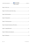
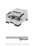
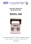
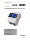
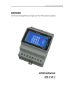
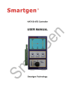
MT6303 meter test bench
User manual
MT6303 Three phase test bench with single position for ANSI and IEC meter
Page 1 of 16
www.meteronic.com
MT6303 meter test bench
User manual
CONTENTS
USER GUIDE ..................................................................................................................................................... 3
1. I NTRODUCTION ......................................................................................................................................... 4
2. TECHNICAL SPECIFICATION ..................................................................................................................... 4
2.1
ELECTRICAL OUTPUT ............................................................................................................................ 4
3. KEYBOARD OPERATION ........................................................................................................................... 6
3.1 OPERATION PANEL’ S BUTTON LAYOUT ................................................................................................... 6
3.2 AFTER- BOOTING MAIN MENU .................................................................................................................. 7
3.3 METER PARAMETER SETTING ................................................................................................................ 7
3.3.1 SELECTION OF THE METER TYPE TO BE TESTED .................................................................................. 7
3.3.2 SETTING OF METER PARAMETERS TO BE TESTED ................................................................................ 8
3.3.3 THE OTHER SETTING: ............................................................................................................................ 8
3.3.4 SYSTEM PARAMETER SETTING: ............................................................................................................ 9
3.3.5 WAVE SETTING ...................................................................................................................................... 9
3.4 STARTING AND CREEPING TEST ..............................................................................................................10
3.4.1 CREEPING TEST: ....................................................................................................................................10
3.4.2 STARTING TEST: ....................................................................................................................................10
3.5 OUTPUT VOLTAGE , CURRENT , AND PHASE ADJUSTMENT: ....................................................................11
3.6 CALIBRATION TEST : .................................................................................................................................11
3.7 CONNECTION ............................................................................................................................................12
3.7.1 A BASE VOLTAGE AND CURRENT TERMINAL ILLUSTRATION ..........................................................12
3.7.2 A BASE 3P4W .......................................................................................................................................12
3.7.3 A BASE 3P3W ......................................................................................................................................13
3.7.4 A BASE 1P2W ......................................................................................................................................13
3.7.5 9S AND 16S BASE SOCKET ..............................................................................................................14
3.7.6 1S BASE SOCKET ..............................................................................................................................15
3.7.7 CONNECTION WITH STANDARD METER ............................................................................................16
Page 2 of 16
www.meteronic.com
MT6303 meter test bench
User manual
User Guide
1.
This user manual and graphics contained in this manual are only applicable to the users of
this equipment and shall not be provided to any third party in any form or way without the
permission of the Company.
2.
This user manual’s copyright and power of interpretation belong to Hangzhou Meteronic
Technology Co., Ltd.; users may not be kept informed of any change of this manual due to
its version upgrade.
3.
This device is a high-precision measurement equipment, so please make sure to read this
manual carefully before use.
4.
Because of the advance in technology and product upgrade, the Company may make
necessary improvement on its products, which may cause some differences between the
device and the manual, but that does not affect the use of it. If you have any question,
please consult us accordingly.
5.
The warranty period of this product is, in principle, one year, but the following cases are
not within the scope of this warranty: the product has been changed arbitrarily or repaired
by any mechanics not belonging to the Company, or has been operated in any wrong way
or used carelessly; any damages caused by accidents or natural disasters, or product has
been exposed to any high-voltage interference or inputted with any abnormal voltage or its
serial number has been changed; this warranty also does not include the disassembling and
removal after its installation and the replacement of any casing, control knobs, and all the
accessories.
6.
Life-long service is available for this product, but service charge will be applied to any
service beyond the warranty period.
Page 3 of 16
www.meteronic.com
MT6303 meter test bench
1.
User manual
Introduction
MT6303 energy meter testing equipment is a kind of desk-top portable energy meter testing device
which is developed and manufactured by Hangzhou meteronic Technology Co. Ltd. and contains
high technology. This device is equipped with a three-phase high-stability program-controlled
power source and MT 5303C three-phase multi-function standard meter developed and
manufactured by the Company; the device can be operated with keyboard to achieve simple
functional tests, or control and management may be realized with personal computer. The PC tester
has a complete range of test items and the testing device has such advantages as high measurement
accuracy, high long-term stability, high degree of automation, wide output range, low distortion,
and high stability.
This device is applicable to the testing of electronic and electromechanical single-phase or
three-phase active or reactive energy meter as well as multi-function energy meter. This device can
provide you with plenty of electrical information such as AC voltage, AC current, inter-phase
voltage and current, power factor, active power, reactive power, apparent power, frequency and etc.
One to three meter stations may be connected to this device with built-in or plug-in error processor.
This device can be used for product test in such areas as product development, product
maintenance, and production lines. Customer may self-develop its own automatic meter calibration
software by making use of the underlying dynamic link library developed by our company.
2.
Technical specification
2.1
Electrical output
2.1.1
Voltage and current measurement range
Output voltage ranges: 57.7V/63.5V and 220V/240V (480V option)
Output current ranges: 0.1A, 1A, 5A, 20A, and 100A
2.1.2 Output load capacity
Voltage loop: Max. 50VA
Current loop: Max 100VA (Measurement range 100A)
2.1.3 Electrical output adjustment
Page 4 of 16
www.meteronic.com
MT6303 meter test bench
User manual
2.1.3.1 Voltage adjustment
a) Adjustment range: 0%~125% selected voltage range
b) Adjustment fineness: four finenesses as 10%, 1%, 0.1%, and 0.01% are available
c) Max. output voltage: 300V or 600V
2.1.3.2 Current adjustment
a) Adjustment range: 0%~120% selected current range
b) Adjustment fineness: four finenesses as 10%, 1%, 0.1%, and 0.01% are available
c) Max. output current: 120A
2.1.3.3 Phase adjustment
a) Adjustment fineness: 0°~359.99°
b) Adjustment fineness: four finenesses as 10°, 1°, 0.1°, and 0.01° are available
2.1.4 Voltage and current output distortion
This device’s voltage and current output distortion will not be more than 0.5% (testing
under linear load)
2.1.5 Output power stability
This device’s pre-set output power will not exceed 0.02% compared with the measurement
range variation within 180S.
2.1.6 Symmetry of electrical outputs from three phases
The difference between any line or phase voltage and its average will not be more than 0.2%;
the difference between any phase current and its average will not be more than 0.2%; the
phase difference between any phase current and its corresponding phase voltage will not be
more than 0.2%.
2.1.7 Harmonic content
a) Number of harmonic waves: 2~31
b) Harmonic content: less than 40% (compared with fundamental wave)
c) Harmonic phase: 0°~359.99°
2.1.8 Monitoring instrument
To be read directly from the standard meter.
2.1.9 Electric pulse
Electric pulse output from standard meter:
1) For error calculator to calculate the error of any meter to be tested;
2) For the reference of upper-level measurement examination and determination agency
when sending the standard meter to them for testing. Please refer to standard meter’s Table
of Constants for pulse constants.
Page 5 of 16
www.meteronic.com
MT6303 meter test bench
User manual
2.1.10 Power supply
Single-phase AC 220V/240V (100V/110V is also applicable), 50/60Hz, max. input power
consumption: 500W.
3.
Keyboard operation
3.1 Operation panel’s button layout
Button guides:
↑↓→←: directions
1%--Imax: rate of loading capacity
0—9: numerical
·: decimal
0.5L,0.8L,1.0,0.8C,0.5C: power factors
Ua,Ub,Uc,Ia,Ib,Ic: switches for corresponding voltage or current outputs
ACB: button for positive and reverse phase sequence switching
Page 6 of 16
www.meteronic.com
MT6303 meter test bench
User manual
Forw: button for forward and reverse current switching
Output adjustment: to adjust the voltage and current amplitudes for their rise or drop; adjust
the voltage and current phase for their lead or lag.
U/I/φ: Voltage, current, and phase adjustment selection
A/B/C: combined and divided phase adjustment.
3.2 After-booting main menu
After booting, the calibration device will initialize the system first automatically; after about 3
seconds later, the following screen will appear:
U(V)
I(A)
Φ(°)
Q(Var)
A
219.96
0.9999
359.95
219.54
B
220.06
1.0001
0.11
220.12
C
220.16
1.0005
359.99
220.96
3P4W W
F=50.00Hz
T=002
C=03200.00
Set to set
3.3
Un=220.00V
Forward I
ABC
Sine Wave
Start to test
Ib=01.000A
Imax=020.0A
Ent to ONLINE
Meter parameter setting
3.3.1 Selection of the meter type to be tested
After coming to the main menu upon booting, press the Set button to reach the setting menu as
shown in the following menu:
Type
Parameter
Other
System
【 * 】 1. 3P3W W
【 】 2. 3P3W60° Var
【 】 3. 3P3W90° Var
【 】 4. 3P3W Var
【 】 5. 3P4W W
【 】 6. 3P4W90° Var
【 】 7. 3P4W Var
【 】 8. 1P2W W
↑↓ or 0-9 to set
Page 7 of 16
www.meteronic.com
MT6303 meter test bench
User manual
Use the Numerical (or Up or Down button) to select the meter type to be tested and “*”
appeared means the selected meter type.
Use the Left or Right button to select the meter parameter to be tested, creeping test,starting
test, and test bench system parameters.
Press ESC button to return to the after-booting main menu.
3.3.2 Setting of meter parameters to be tested
Type
Parameter
Other
System
【 * 】 Un=220.00V
【 】 Ib=05.000A
【 】 F=50.00Hz
【 】 T=005
【 】 Tmax=006
【 】 Tmin=001
【 】 C=03200.00p/kVarh
【 】 Imax=020.0A
【 】 Class=1.0
0-9 to set
F1 to select r or p
Use the Up or Down button and move the
“ ”
*
to select corresponding setting items, and press
Numerical and Decimal buttons to set required value.
press Ent for confirmation.
Press ESC button to return to the after-booting main menu.
The frequency range to be set is 45.00Hz - 65.00Hz.
Press F1 to select constants’ settings: if constant’s unit is “p/kWh”, current setting is for
electronic meter (represented by p);if constant’s unit is “r/kWh”, current setting is for
mechanical meter (represented by r).
3.3.3 The other setting:
Use the Up or Down button and move the “*” to select corresponding setting items, and press
Numerical and Decimal buttons to set required value.
press Ent for confirmation.
Press ESC button to return to the after-booting main menu.
Page 8 of 16
www.meteronic.com
MT6303 meter test bench
User manual
Type
Parameter
Other
System
【 * 】 Creep U 100%Un
【
】 Creep I 000.0 mA
【
】 Creep T 0060 S
【
】 Start I 010.0 mA
【
】 Start I 0300 S
0-9 to set
3.3.4 System parameter setting:
Type
Parameter
Other
System
【 * 】 Angle Modify:on
【 】 Range Modify:on
【 】 Pulse Input:↑
【 】 Output:Y
Ent to set
Use the Up or Down button to move the “* ” to select corresponding setting items, and press
Ent for confirmation.
Press ESC button to return to the after-booting main menu.
3.3.5 Wave setting
After coming to the main menu upon booting, press wave button to reach the setting menu, and
the following screen will appear:
Page 9 of 16
www.meteronic.com
MT6303 meter test bench
User manual
Wave Type
【 * 】 Sine Wave
Ent to set
ESC to Quit
Press Ent for selection (Sine wave, sub-group wave, harmonic wave, and conduction angle
control)
3.4 Starting and creeping test
3.4.1 creeping test:
After creeping test parameter setting has been completed on setting menu, return to the
after-booting main menu, press F3 button for creeping test and the following menu will appear:
U(V)
I(A)
Φ(°)
Q(Var)
A
219.96
0.0100
0.01
2.20
B
220.06
0.0100
359.95
2.21
C
220.16
0.0100
0.01
2.19
1
2
3
Set :0060 S
Real:0032 S
P
:00
Set :0060 S
Real:0032 S
P
:00
Set :0060 S
Real:0032 S
P
:00
ESC to Quit
3.4.2 Starting test:
After starting test parameter setting has been completed on setting menu, return to the
after-booting main menu, press the F2 button for starting test and the following menu will
appear:
Page 10 of 16
www.meteronic.com
MT6303 meter test bench
User manual
U(V)
I(A)
Φ(°)
Q(Var)
A
219.96
0.0100
0.01
2.20
B
220.06
0.0100
359.95
2.21
C
220.16
0.0100
0.01
2.19
1
2
3
Set :0060 S
Real:0032 S
P
:00
Set :0060 S
Real:0032 S
P
:00
Set :0060 S
Real:0032 S
P :00
ESC to Quit
3.5 Output voltage, current, and phase adjustment:
In each test state, press U/I/φ to select the adjustment type, and press A/B/C to select the phase
to be adjusted; select corresponding button based on the value to be adjusted.
If U or I is selected, the adjustment fineness is 10%, 1%, 0.1%, and 0.01%.
If φ is selected, the adjustment fineness is 10°, 1°, 0.1°, and 0.01°.
3.6 Calibration test:
After the setting of meter type, meter parameter and so on has been completed on setting menu,
press the Start button for error test and the following screen will appear:
Notes: 1, 2, and 3 stand for the three meter stations, corresponding separately to the three
aviation ports P1, P2, and P3 on the rear power source board.
Err1, Err2, and Err3 stand for the first three errors and every new error after that will be shown
in Err3.
In calibration state, you may go to the setting interface and set the number of turns, maximum
and minimum numbers of turns, electrical constants and so on for easy testing.
U(V)
I(A)
Φ(°)
Q(Var)
A
219.96
0.9999
359.95
219.54
B
220.06
1.0001
0.11
220.12
C
220.16
1.0005
359.99
220.96
1
Page 11 of 16
2
3
Err1:0.0250% Err1: --- % Err1: ---
%
Err2:0.0256% Err2: --- % Err2: --Err3:0.0245% Err3: --- % Err3: ---
%
%
ESC to Quit
www.meteronic.com
MT6303 meter test bench
User manual
3.7 Connection
3.7.1
A BASE Voltage and current terminal illustration
Ian
Ibn
Icn
Ia*
Ib*
Ic*
Current terminal
Voltage terminal
UA
3.7.2
UB
UC
N
3L
UN
A Base 3P4W
1S
2S
UA
3S
UB
UC
2L
1L
UN
Note: UA to be connected with 1S, UB with 2S, UC with 3S, UN with N
Page 12 of 16
www.meteronic.com
MT6303 meter test bench
3.7.3
User manual
A BASE 3P3W
1S
2S
UA
3L
3S
UB
UC
2L
1L
UN
Note: UA to be connected with 1S, UB with 2S, UC with 3S
3.7.4
A BASE 1P2W
1S
2S
2L
1L
UA
UB
UC
UN
Note: UA to be connected with 1S, UN with 2S
Page 13 of 16
www.meteronic.com
MT6303 meter test bench
3.7.5
User manual
9S and 16S BASE SOCKET
UA
UC
UB
UA
UB
UN
UA UB UC
UC
UN
UN
Ia*
Ib*
UA
Page 14 of 16
Ian
Ic*
UB
UC
Ibn
Icn
UN
www.meteronic.com
MT6303 meter test bench
3.7.6
User manual
1S BASE SOCKET
UA
UC
UB
UA
UB
UN
UA UB UC
UC
UN
UN
Ia*
Ib*
UA
Ian
Ic*
UB
UC
Ibn
Icn
UN
Note: 1. Please remove the Ic* and Icn from the A BASE terminal and connect with BASE
SOCKET。
2. Connect A BASE voltage terminal UA wth S BASE SOCKET UA, connect A BASE
voltage terminal UN with S BASE SOCKET UC
Page 15 of 16
www.meteronic.com
MT6303 meter test bench
3.7.7
User manual
Connection with standard meter
RS-232
fH
fL
UA
UC
UN
100A
COM
100A
COM
100A
COM
I O
UB
1A
1A
1A
40V-480V
Current
100A
COM
100A
COM
100A
COM
1A
COM
1A
COM
1A
COM
Voltage
Power
Switch
P1
P2
RSM
P3
fH
PC
UA
UB
UC
UN
If you have any question, please contact us.
Contact person: Mr. Ming Stone
Hangzhou Meteronic Technology Co., Ltd.
Add.:
No. 10, 3rd Xiyuan Rd.
Hangzhou Westlake Industrial Park
Hangzhou city, Zhejiang province 310030 China
Tel.:
+86 (0)571 8894 8756
Fax:
+86 (0)571 8894 8760
Mobile: +86 137 1816 9410
Email:
[email protected]
Website: www.meteronic.com
Page 16 of 16
www.meteronic.com