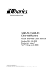
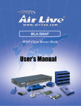
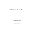
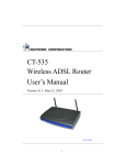
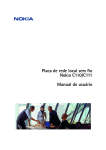
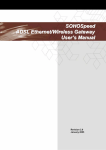
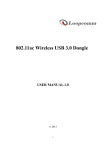
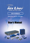
1
WIRELESS ROUTER
USER MANUAL
Rev. 1.0
Table of Contents
INSTALLING YOUR ROUTER
1
System Requirements
1
Installation Instructions
1
PREPARING YOUR NETWORK
2
Configuring Windows for IP Networking
2
Collecting ISP Information
6
BASIC FUNCTIONS
7
Setup
9
Global Address
13
Wireless
17
Tools
25
Status
28
DHCP
31
Log
35
Statistics
38
ADVANCED FUNCTIONS
40
Virtual Servers
41
Filters
44
IP Block
48
Special Apps
50
DMZ Host
54
MAC Clone
56
Dynamic DNS
57
Proxy DNS
59
Parental Control
61
1
Chapter
H A R D W A R E
I N S T A L L A T I O N
Installing Your Router
In this chapter, you’ll learn how to connect your router.
System Requirements
One or more PCs (desktop or notebook) with Ethernet interface
Broadband Internet access
Ethernet cables
Wireless interface (if planning to use wireless functions)
Installation Instructions
TO CONNECT THE ROUTER HARDWARE:
1.
Make sure all equipment is turned off, including the router, your PC(s), and your
cable or DSL modem (if applicable).
2.
Connect the WAN port on the router to your cable modem, DSL modem, Ethernet
Server, or hub.
3.
Connect one or more client PCs to the LAN port(s).
4.
Connect the power adapter (5VDC, 1.2A) to the power jack on the router. Then,
plug the power cable into an outlet.
5.
Turn on your PC(s).
1
2
Chapter
P R E P A R I N G
Y O U R
N E T W O R K
Preparing Your Network
In this chapter, you’ll learn what to do before configuring your router.
B
efore you can configure your router, you need to set up all the computers on your
network for TCP/IP networking. You also need to know certain information from your ISP.
Configuring Windows for IP Networking
You need to configure each computer in your network for TCP/IP networking. If you plan to
use the DHCP feature (recommended), you should configure each computer to receive an IP
address automatically. See the procedure below for instructions.
If you don’t plan to use DHCP, you’ll need to manually assign an IP address to each computer.
Refer to your Windows documentation for instructions on how to do this.
TO CONFIGURE WINDOWS TO RECEIVE DYNAMIC IP ADRESSES:
1.
Click Start, then choose Settings -> Network and Dial-up Connections ->
[name of your ISP connection].
A Status dialog box will appear:
2
B A S I C
F U N C T I O N S
FIGURE 1. ISP Connection Status Dialog Box
2.
Click Properties.
A Properties dialog box will appear:
3
B A S I C
F U N C T I O N S
FIGURE 2. ISP Connection Properties Dialog Box
3.
Click Internet Protocol (TCP/IP), then click Properties.
4
B A S I C
F U N C T I O N S
A TCP/IP Properties dialog box will appear:
FIGURE 3. TCP/IP Properties Dialog Box
4.
Click Obtain an IP address automatically and Obtain DNS server address
automatically.
5.
Click OK. You may need to restart your computer.
Note
This procedure applies to Windows 2000 operating systems only. For Windows
95/98/ME, Windows NT, or Windows XP, consult your Windows
documentation.
5
B A S I C
F U N C T I O N S
Collecting ISP Information
You will need to find out some information from your ISP before you can configure your router,
such as:
Has your ISP assigned you a static IP address, or will they assign one to you dynamically?
If they have given you a static IP, what is it?
Does your ISP use PPPoE? If so, what is your PPPoE username and password?
Call your ISP if you’re not sure of the answers to these questions.
6
3
Chapter
B A S I C
F U N C T I O N S
Basic Functions
T
Basic administrative functions include Setup, Global Address,
Wireless, Tools, Status, DHCP, and Log.
he router comes with a web-based tool that you can use to set up and customize the
router settings. You can access this tool from any computer on your network.
Note
For best results, use Microsoft Internet Explorer version 5.0 or later.
TO OPEN THE WEB-BASED ADMIN TOOL:
1.
Open a browser on your PC.
2.
Type http://192.168.62.1 in the Address field:
FIGURE 4. Web Address for Admin Tool
A logon dialog box will appear:
FIGURE 5. Username/Password Dialog Box
3.
Type admin in the User Name field. Then, type a Password and click OK. The
default password is 1234.
The router Admin Tool will appear.
Note
The web-based Admin Tool will log you out after a certain period of idle time. If
this happens, you will need to re-enter your username and password.
8
Setup
The Setup screen shows the basic configuration parameters for your router, such as Host Name,
LAN IP Address, and PPPoE Login.
Although most users will be able to accept the default settings, every Internet Service Provider
(ISP) is different. Check with your ISP if you're not sure which settings they require.
The Setup screen is shown in the figure below.
9
FIGURE 6. Setup Screen
Note
The graphics shown in this manual may differ slightly from your router’s screens.
The images that appear here are provided as examples only.
TO CONFIGURE SETUP PARAMETERS:
1.
Type the Host Name (optional). This value is sometimes called System Name or
Account Name.
Check with your ISP if you’re not sure whether to provide this information.
2.
Type the Domain Name of your ISP, such as xyz.isp.com (optional).
10
Check with your ISP if you’re not sure whether to provide this information.
3.
Review the Firmware Version. This value tells you the version number and date of
the firmware you are currently using.
4.
Select your Time Zone.
5.
Enable or disable Daylight Savings.
6.
Review the LAN IP Address information and change it if necessary.
These fields show the Device IP Address and Subnet Mask as seen by others on your
Local Area Network (LAN). Most users will not need to change these values.
Note
If you change the LAN IP Address with the DHCP server running, you'll need
to restart your client machines. If you change the LAN IP Address without the
DHCP server running, you'll need to manually reconfigure your clients' IP
addresses.
7.
If you have enabled the DMZ feature, review the DMZ IP Address information and
change it if necessary.
These fields show the DMZ IP Address and Subnet Mask as seen by others on your
Local Area Network (LAN). Most users will not need to change these values.
8.
For WAN IP Address (also called the Public IP), choose either Obtain an IP
Address Automatically (most users) or Specify an IP Address (if your ISP assigns
static IPs).
If you choose the second option, type in the Wide Area Network (WAN) IP Address,
Subnet Mask, ISP Gateway Address, and DNS information. Your ISP should provide
these values.
9.
Select your Point-to-Point Protocol over Ethernet (PPPoE) settings. PPPoE allows
your ISP to authenticate your connection by requiring you to submit a username and
password.
If your ISP uses PPPoE, choose Enable and go on to Step 7; otherwise, choose Disable
and skip to Step 9.
11
Warning
If you enable PPPoE, make sure to uninstall any existing PPPoE applications
on any of the PCs in your network.
10. Type in the PPPoE User Name and Password provided by your ISP.
11. Click Apply when you finish choosing your settings, or click Cancel to undo your
changes.
12
Global Address
Use the Global Address screen to set up Network Address Translation (NAT), a process that
provides internal to external IP address mapping. If your router is configured to retrieve an IP
address dynamically, you will not need to use this function.
Note
In order to use the Global Address mapping function, you must have NAT enabled
in the Filters screen. See Filters on page 44 for more information.
The Global Address screen is shown in the figure below.
FIGURE 7. Global Address Screen
13
TO SET UP GLOBAL ADDRESSES:
1.
Review the first line in the table. It shows the default WAN IP address (specified in
the Setup screen). If your ISP assigns you an IP address automatically, that address
will be shown here.
2.
In the spaces provided for lines 2 - 8, list up to seven additional static external IP
addresses provided by your ISP.
3.
Click Apply when you finish choosing your settings, or click Cancel to undo your
changes.
14
The Global Address screen as it appears with the DMZ featured enabled is shown in the figure
below.
FIGURE 8. Global Address Screen With DMZ Enabled
TO SET UP GLOBAL ADDRESSES WITH THE DMZ FEATURE ENABLED:
1.
Review the first line in the table. It shows the default WAN IP address (specified in
the Setup screen). If your ISP assigns you an IP address automatically, that address
will be shown here.
2.
In the External – Internal fields, list up to six static, external IP addresses provided
by your ISP.
3.
Define global IP addresses for your DMZ network in the External – DMZ fields.
List up to six static, external IP addresses provided by your ISP.
15
4.
Click Apply when you finish choosing your settings, or click Cancel to undo your
changes.
TO REMOVE GLOBAL ADDRESSES:
Enter 0.0.0.0 and click Apply to delete any unwanted entries.
16
Wireless
Use the Wireless screen to configure your router for wireless access. Most users will only need to
look at the Basic settings, which include Wireless Enable/Disable, ESSID, Channel, and WEP
options.
Some users may choose to configure the Advanced wireless settings, such as Beacon Interval,
Authentication Type, and Enhanced Security options.
The Wireless screen is shown in the figure below.
17
FIGURE 9. Wireless Screen
TO CONFIGURE THE BASIC WIRELESS OPTIONS:
1.
First, choose to Enable or Disable wireless access.
None of the router’s wireless functions will work unless you choose Enable.
2.
Type in the Extended Service Set Identifier (ESSID).
The ESSID is the unique identifier shared by all the clients in a wireless network. It is
case-sensitive and cannot exceed 32 characters.
3.
Type the Channel number (between 1 and 11).
18
The Channel field specifies the default IEEE 802.11b channel for wireless LAN
transmissions.
4.
Choose to Enable or Disable Wired Equivalent Privacy (WEP).
If you choose Enable, you can click Set WEP Keys to launch a separate browser window
that will allow you to specify security keys. See the procedure below, TO SET WEP KEYS,
for instructions on how to do this.
5.
If you want to configure the advanced wireless settings, go on to the procedure below,
TO CONFIGURE THE ADVANCED WIRELESS OPTIONS.
If you are finished configuring your wireless settings, click Apply to put your changes in
effect, or click Cancel to undo your changes.
TO SET WEP KEYS:
1.
Click Set WEP Keys in the Basic Settings area of the Wireless screen to launch a
separate browser window that will allow you to specify security keys.
The Set WEP Keys window is shown in the figure below.
FIGURE 10. Set WEP Keys Window
2.
In the Set WEP Keys window, select the Encryption Level (64 Bit or 128 Bit).
19
Note
Although 128 Bit encryption uses a more secure encryption algorithm, it can
slow down your network’s data transmission rates.
3.
Specify WEP keys by entering a Passphrase and clicking Generate, or by manually
typing up to four keys. Use the Clear Keys button to delete any unwanted key
information.
Note
You can create any Passphrase you like, but be sure to write it down so that you
can refer to it later if necessary.
4.
Select the Default TX Key from the drop-down list. This value will determine the
default encryption key to be used.
5.
Click Apply to put your changes in effect, or click Cancel to undo your changes.
Click Refresh to see the latest data.
6.
Close the window when you are finished.
20
Advanced Wireless Options
Most users will not need to configure the advanced wireless options.
TO CONFIGURE THE ADVANCED WIRELESS OPTIONS:
1.
Review the FirmWare Version. This value tells you the version number of the
wireless firmware you are currently using.
2.
Type a Beacon Interval. This value represents the time interval between beacons
broadcast by the Access Point (AP).
Note that the default values for the advanced wireless settings are shown in a table on the
right-hand side of the screen:
FIGURE 11. Defaults for Advanced Wireless Settings
3.
Type a value for RTS Threshold.
This value represents the minimum size of data frames above which Request-To-Send
(RTS) protocol is used. RTS helps prevent data collision from hidden nodes.
4.
Type a value for Fragmentation.
For efficiency in high-traffic situations, large files are split into fragments. This parameter
specifies the default packet size.
5.
Type a value for DTIM Interval.
This parameter specifies the number of beacon intervals between successive Delivery
Traffic Indication Maps (DTIMs).
6.
Type a value for Max Stations.
21
This parameter specifies the maximum number of wireless stations allowed to associate.
7.
Choose either 1-2MBps or 1-2-5.5-11MBps for Basic Rates.
8.
Choose either 1-2MBps or 1-2-5.5-11MBps for TX Rates (Transmission Rates).
9.
Choose a Preamble Type, either Short (72 bits) or Long (144 bits).
10. Choose an Authentication Type, either Open System, Shared Key, or Both.
11. Choose whether to Enable or Disable the Enhanced Security measures.
If you click Enable, you can then choose to hide your Service Set Identifier (SSID) or to
block unspecified SSIDs.
12. Click Apply to put your changes in effect, or click Cancel to undo your changes.
Wireless Access Control
Use the Wireless Control List window to allow access to the Internet based on users’ Media
Access Control (MAC) address.
TO SET WIRELESS ACCESS CONTROLS:
1.
Click On.
2.
Click the Set Access List button on the Filters screen to launch the Wireless Control
List window:
22
FIGURE 12. Wireless Control List Window
Note
The above graphic does not show the entire Wireless Control List window.
3.
Type the MAC address(es) that you want to allow into the table. You can allow access
to up to 80 addresses.
4.
Click Refresh to automatically update the values in the table.
5.
To save your changes, click Submit at the bottom of the Wireless Control list; then
close the window.
Association Table
The Wireless Association lists all of the wireless devices of which the access point is aware.
TO DISPLAY THE WIRELESS ASSOCIATION TABLE
1.
Click Display Association Table to launch the Wireless Association Table:
23
FIGURE 13. Wireless Association Window
2.
Click Refresh to automatically update the values in the table.
3.
Click Add to add a new device to the wireless access control list. The address is added
to the Wireless Control List table.
4.
Click Delete to remove a device from the wireless access control list. The address is
deleted from the Wireless Control List table.
If you are finished setting up your filters, click Apply to put your changes in effect, or click
Cancel to undo your changes.
24
Tools
Use the Tools screen to:
Change the administrative password for your router
Restore the factory default settings
Perform a firmware upgrade
We strongly recommend that you change the password once you’ve accessed the router for the
first time.
The Tools screen is shown in the figure below.
FIGURE 14. Tools Screen
TO CHANGE THE ADMINISTRATIVE PASSWORD:
1.
Type in the Old Password. The factory default password is 1234.
2.
Enter a New Password. The password you choose must be less than 64 characters.
25
3.
Confirm your password in the Confirm Password field.
4.
Click Apply to put your changes in effect, or click Cancel to undo your changes.
Note
We strongly recommend that you change your password regularly for security
purposes.
TO RESTORE THE FACTORY DEFAULT SETTINGS:
1.
Click Restore to Default.
A warning dialog box appears:
FIGURE 15. Warning Dialog Box for Restore Defaults
2.
Click OK.
All your router’s settings will be restored to their factory default values.
Warning
Restoring the factory defaults will reset all of the router’s settings in every
screen. Once you have restored the factory defaults, you will have to reconfigure the router settings from scratch. Because of this, write down all your
settings before restoring the defaults.
TO UPGRADE THE ROUTER’S FIRMWARE:
1.
Download a firmware image file from the router website and save it to your hard
drive. Make sure to write down the file location.
2.
Type the filename and path location directly into the Upgrade Firmware field, or
click Browse… to launch the Choose file dialog box:
26
FIGURE 16. Choose File Dialog Box for Firmware Upgrade
Locate the firmware you downloaded and click Open.
3.
Click Upgrade Now. The firmware of the device will be upgraded.
Warning
Upgrading the firmware takes about 30 seconds. Don’t power down the router
while the firmware upgrade operation is in progress.
27
Status
The Status screen is a read-only display that gives you information about your router. The data
displayed may change depending on your current configuration.
The Status screen is shown in the figure below.
28
FIGURE 17. Status Screen
The displayed data may include:
Host Name
Domain
PPPoE Login (Enabled or Disabled)
LAN settings (IP Address and Subnet Mask)
DMZ settings (IP Address and Subnet Mask)
29
WAN settings (IP Address, Subnet Mask, Default Gateway, and DNS information)
DDNS (Dynamic DNS) status (Server and Status)
To change any of these settings, go to the Setup screen.
DHCP Release and DHCP Renew
If you chose the Dynamic IP and PPPoE Disable options in the Setup screen, you’ll see the
DHCP Release and DHCP Renew buttons below the status information. Use these buttons to
release or renew the WAN IP address.
TO RELEASE THE WAN IP ADDRESS:
Click DHCP Release.
TO RENEW THE WAN IP ADDRESS:
Click DHCP Renew.
30
DHCP
Use the DHCP screen to set up your router as a Dynamic Host Configuration Protocol (DHCP)
server. DHCP servers automatically assign IP addresses to all the clients on your network.
Note
If you don’t enable DHCP on your router, you’ll need to manually configure an IP
address for each computer on your network.
The DHCP screen is shown in the figure below.
FIGURE 18. DHCP Screen
TO SET UP YOUR ROUTER AS A DHCP SERVER:
1.
Make sure there is not already a DHCP server running on your network.
2.
Make sure that each computer on your network is configured to receive an IP address
automatically.
3.
On the DHCP screen, click Enable.
31
4.
Type the IP Pool Starting Address. The address you specify will be the first IP
address that can be assigned to a computer on the network.
4.
Type the IP Pool Ending Address. The address you specify will be the last IP
address that can be assigned.
Example
If you choose 192.168.1.51 as the starting address and 192.168.1.100 as the
ending address, the DHCP server will assign addresses to network clients that
are between 192.168.1.51 and 192.168.1.100.
5.
Click Apply to put your changes in effect, or click Cancel to undo your changes.
TO SET UP YOUR ROUTER AS A DHCP SERVER WHEN USING THE DMZ
FEATURE:
1.
Make sure there is not already a DHCP server running on your network.
2.
Make sure that each computer on your network is configured to receive an IP address
automatically.
3.
On the DHCP screen, click Enable (Internal).
FIGURE 19. DHCP Screen With DMZ Enabled
4.
Type the IP Pool Starting Address. The address you specify will be the first IP
address that can be assigned to a computer on the network.
32
5.
Type the IP Pool Ending Address. The address you specify will be the last IP
address that can be assigned.
Example
If you choose 192.168.1.51 as the starting address and 192.168.1.100 as the
ending address, the DHCP server will assign addresses to network clients that
are between 192.168.1.51 and 192.168.1.100.
6.
Click Enable (DMZ).
5.
Type the IP Pool Starting Address. The address you specify will be the first IP
address that can be assigned to a computer on the DMZ network.
6.
Type the IP Pool Ending Address. The address you specify will be the last IP
address that can be assigned to a computer on the DMZ network.
7.
Click Apply to put your changes in effect, or click Cancel to undo your changes.
Display DHCP Table
Click Display DHCP Table to launch the DHCP Active IP window. In this screen, the DHCP
Active IP Table lists information about the computers that have been assigned IP addresses by
the DHCP server. For each active client, the table shows:
Index number
Client Hostname
IP Address
Mac Address
In addition, the DHCP Server IP Address is listed above the table.
If you have enabled the DMZ or LAN features, the DHCP screen allows you to view the DHCP
Active IP Table for DMZ Zone window and/or the DHCP Active IP Table for LAN.
You can click Refresh to see the latest data. Close the window when you are finished looking at
the table.
The DHCP Active IP window is shown in the figure below.
33
FIGURE 20. DHCP Active IP Window
The DHCP Active IP Table for DMZ Zone window is shown in the figure below.
FIGURE 21. DHCP Active IP Table for DMZ Zone Window
The DHCP Active IP Table for LAN window is shown in the figure below.
FIGURE 22. DHCP Active IP Table for LAN Window
34
Log
Use the Log screen to set up and view log files that record the access activity of LAN and WAN
clients.
The Log screen is shown in the figure below.
FIGURE 23. Log Screen
TO SET UP LOGGING ON YOUR ROUTER:
1.
Click Enable for Access Log on the Log screen.
2.
Click Apply to put your changes in effect, or click Cancel to undo your changes.
Session Event Log
Click Session Event Log to launch the Session Event Log window. In this screen, the Session
Event Log Table lists session event entries. The table shows the Index number, Transport
Type, Source IP, Source Port, Destination IP, Destination Port, and Terminate Reason for
each event.
You can click Refresh to see the latest data. Make sure to close the window when you are
finished looking at the log.
35
The Session Event Log is shown in the figure below.
FIGURE 24. Session Event Log
Block Event Log
Click Block Event Log to launch the Block Event Log window. In this screen, the Block Event
Log Table lists blocking event entries. The table shows the Index number, Transport Type,
Source IP, Source Port, Destination IP, Destination Port, and Terminate Reason for each
event.
You can click Refresh to see the latest data. Make sure to close the window when you are
finished looking at the log.
The Block Event Log is shown in the figure below.
FIGURE 25. Block Event Log
Intrusion Event Log
Click Intrusion Event Log to launch the Intrusion Event Log window. In this screen, the
Intrusion Event Log Table lists intrusion event entries. The table shows the Index number,
Record Time, and Intrusion Type for each intrusion event.
You can click Refresh to see the latest data. Make sure to close the window when you are
finished looking at the log.
The Intrusion Event Log is shown in the figure below.
36
FIGURE 26. Intrusion Event Log
Wireless Event Log
Click Wireless Event Log to launch the Wireless Event Log window. In this screen, the Wireless
Event Log table lists wireless event entries. The table shows the Index number, Time, Severity,
and Description for each event.
You can click Refresh to see the latest data. Make sure to close the window when you are
finished looking at the log.
The Wireless Event Log is shown in the figure below.
FIGURE 27. Wireless Event Log
37
Statistics
Use the Statistics screen to view statistics for the LAN, WAN, and AP Radio ports.
The Statistics screen is shown in the figure below.
FIGURE 28. Statistics Screen
LAN Statistics
This table lists detailed statistics on the LAN port.
38
WAN Statistics
This table lists detailed statistics on the WAN port.
AP Radio
This table lists detailed statistics on the access point's radio.
39
4
Chapter
Advanced Functions
T
Advanced administrative functions include Virtual Servers, Filters,
Special Apps, DMZ Host, and MAC Clone.
he web-based Admin Tool allows you to set up advanced services and perform special
functions, such as filtering or cloning your MAC address. Most users will not need to use
these features.
TO TOGGLE BETWEEN BASIC AND ADVANCED FUNCTIONS:
1.
From the Basic functions screen set, click Advanced on the far right side of the
menu bar to access the Advanced screens:
FIGURE 29. Advanced Button
2.
Once you are in the Advanced screen set, click Basic on the far right side of the
menu bar to return to the Basic screens:
FIGURE 30. Basic Button
40
Virtual Servers
Use the Virtual Servers screen to provide remote services, such as FTP or Telnet, from computers
in your network.
Note
Configuring virtual servers may cause filters to be automatically created for you in
the Filters screen.
The Virtual Servers screen is shown in the figure below.
41
FIGURE 31. Virtual Servers Screen
TO SET UP A COMPUTER ON YOUR NETWORK AS A VIRTUAL SERVER:
1.
If you have the DMZ feature enabled, select an option from the Choose Interface
list. If your gateway is configured to retrieve an IP address dynamically, you do not
see this field.
If you want to set up Virtual Servers in your LAN network, choose ExternalInternal.
If you want to set up Virtual Servers in your DMZ network, choose ExternalDMZ.
2.
If your computer is using the Windows XP operating system, type a name for the
service in the Service field.
Note
The Service field is only available for computers using Windows XP. Windows
XP takes advantage of the Universal Plug and Play (UPnP) features of the
router. This allows computers that support UPnP to identify the router
automatically.
3.
Select a Public IP Address from the drop-down list.
42
Note
The IP address of any computer being used as a DMZ host will not appear in
the list.
4.
Specify a Service Port. For help on which port to choose, refer to the Well-known
Ports table on the right-hand side of the screen:
FIGURE 32. Well-known Ports Table
5.
Select a Protocol (TCP, UDP, or Both) from the drop-down list.
6.
Specify the Private IP Address. You only need to type the last part of the address;
the first part is set automatically.
7.
Click Apply to put your changes in effect, or click Cancel to undo your changes.
TO DELETE VIRTUAL SERVERS:
For any Virtual Server you want to delete, select 0.0.0.0 for Public IP Address and
click Apply.
43
Filters
If no filters are
enabled, all traffic
will be blocked.
Use the Filters screen to create and apply filters that can selectively allow
traffic to pass in and out of your network. Your router comes with several
filters predefined for you.
Warning
Overwriting the factory default filters may result in your network clients not being
able to access the Internet. When you define new filters, we recommend that you
choose an empty row.
The Filters screen is shown in the figure below.
44
FIGURE 33. Filters Screen
TO SET UP A FILTER:
8.
Select the Filtering Page from the drop-down list (1~12, 13~24, or 25~36).
Note
You may define up to 36 filters.
9.
Select the Filtering Layer from the drop-down list, either Raw IP or Port Filtering.
10. If you chose Raw IP, enter the Proto Num (the IP Protocol Number, between 0
and 255). If you chose Port Filtering, skip to Step 4.
45
Warning
Do not enter a Proto Num of 6 (TCP) or 17 (UDP), or the port filters will not
work.
11. Select the Direction from the drop-down list, either InBound, Outbound, or Both.
12. If you chose Port Filtering in Step 2, type the Private Port Range (the range of
ports that you want to allow) and select the Protocol from the drop-down list (TCP,
UDP, or Both). If you chose Raw IP in Step 2, skip to Step 6.
6.
If you want to set up MAC filters or configure additional filtering options, go on to
the procedure below, TO SET MAC FILTERS.
If you are finished setting up your filters, click Apply to put your changes in effect, or
click Cancel to undo your changes.
Warning
In addition to the factory default filters, filters can be created automatically to
allow your Virtual Servers or Special Applications to function. Overwriting or
deleting these filters may disable some applications or services.
Additional Filtering Options
You can enable additional filtering options, such as Remote Management, IPSec Pass Through,
and Intrusion Detection.
Note
We recommend that you keep the default settings if you’re not sure whether to
change these options.
TO CONFIGURE ADDITIONAL FILTERING OPTIONS:
1.
Choose whether to Enable or Disable each filtering option. The options are
summarized in the table below.
NAT
Enabling this feature allows you to set up Network Address Translation
(NAT).
Firewall
Enabling this feature allows you to protect your network with a firewall.
Remote Management
46
Enabling this feature lets you access your router’s web-based admin tool
through your WAN connection.
IPSec Pass Through
Enabling this feature lets you use IP Security Pass Through.
PPTP Pass Through
Enabling this feature lets you use Point-to-Point Tunneling Protocol
(PPTP), used to enable VPN sessions.
Intrusion Detection
Enabling this feature allows you to detect and record intrusion attempts
into your network.
2.
Click Apply to put your changes in effect, or click Cancel to undo your changes.
Deleting Filters
You can delete existing filters from the filter list.
Warning
Deleting factory default filters, or filters that are associated with your Virtual Servers
or Special Applications, may disable key features or services.
TO DELETE A RAW IP FILTER:
1.
Type zero in the Proto Num field.
2.
Click Apply.
TO DELETE A PORT FILTERING FILTER:
1.
Type zero in both Private Port Range fields.
2.
Click Apply.
47
IP Block
Use the IP Block screen to create and apply filters to selectively block traffic from specific IP
addresses from passing in and out of your network.
You can block a single IP address or a range of IP addresses. If the IP address in the left IP field
(the From field) is the same as the IP address in the right IP field (the To field), a single IP
address is blocked.
Note
This feature blocks traffic in both directions from the specified IP addresses.
The IP Block screen is shown in the figure below.
48
FIGURE 34. IP Block Screen
TO BLOCK A RANGE OF IP ADDRESSES:
1.
Type the first IP address of the range in the To field.
2.
Type the last IP address of the range in the From field.
3.
Click Apply to put your changes in effect, or click Cancel to undo your changes.
TO REMOVE A BLOCK AGAINST IP ADDRESSES:
For any IP block that you want to delete, type 0.0.0.0 for both IP ranges and click Apply.
49
Special Apps
Use the Special Applications screen to allow certain ports to communicate with computers
outside your network. This feature may be necessary for multi-session applications like online
gaming and video conferencing.
Note
Configuring special applications may cause filters to be automatically created for you
in the Filters screen.
The Special Apps screen is shown in the figure below.
50
FIGURE 35. Special Apps Screen
Warning
The first two lines of the table are pre-configured for FTP and NetMeeting. If you
overwrite these lines, those applications will not work.
TO CONFIGURE
FEATURE:
1.
SPECIAL APPS USING THE POPULAR APPLICATIONS
Select the application you wish to enable from the Popular Applications drop-down
list:
FIGURE 36. Popular Applications Feature
2.
Choose a specific line in the table by selecting its number from the ID drop-down list.
3.
Click Copy to.
51
The configuration settings for the selected application will appear in the table.
4.
Click Apply to put your changes in effect, or click Cancel to undo your changes.
Manual Configuration
Although you can manually configure special applications, only expert users should do so. We
recommend that you always use the Popular Applications feature unless you know exactly which
settings to choose.
TO MANUALLY CONFIGURE SPECIAL APPS:
1.
Choose a line item to configure.
Note
If you overwrite a line that is already configured for another special application,
that application will not work.
2.
Select the communication Protocol used by the application from the drop-down list
(TCP, UDP, or Both).
3.
Specify a Trigger Port Range.
This parameter identifies the range of ports that, when used for outgoing traffic, will
trigger the gateway to accept certain incoming requests.
4.
Type a Maximum Activity Interval.
This parameter specifies the maximum number of milliseconds after the port trigger
action during which incoming requests will be accepted.
5.
Choose Enable or Disable from the drop-down list for Session Chaining.
This parameter specifies whether or not dynamic sessions can be chained, allowing multilevel session triggering.
6.
If you chose Enable in Step 5, you may now choose Enable or Disable for
Chaining on UDP. If you chose Disable in Step 5, skip to Step 7.
7.
Choose Enable or Disable from the drop-down list for Address Replacement.
This parameter specifies whether or not binary address replacement should be performed.
8.
If you chose Enable in Step 7, you may now choose the Address Translation Type
(TCP or UDP). If you chose Disable in Step 7, skip to Step 9.
9.
Choose Enable or Disable from the drop-down list for Multi Hosts.
52
Enabling this parameter allows a new session to be initiated from/to different remote
hosts.
10. Click Apply to put your changes in effect, or click Cancel to undo your changes.
TO DELETE A SPECIAL APPLICATION:
1.
Enter 0 - 0 for Trigger Port Range.
2.
Click Apply.
53
DMZ Host
Use the DMZ Host screen to expose one or more computers on your network to the Internet.
This feature is often used for online games that require unrestricted two-way communication.
The total number of DMZ hosts you can have is limited by the total number of Global Addresses
that you have configured in the Global Address screen. For example, if you have defined five
Global Addresses (including the Default Public IP), you are limited to five DMZ hosts.
Since the maximum number of Global Addresses is eight, the total number of DMZ hosts you
can configure is also eight.
Warning
Computers you designate as Demilitarized Zones (DMZs) won’t have any firewall
protection.
The DMZ Host screen is shown in the figure below.
54
FIGURE 37. DMZ Host Screen
TO SET UP A COMPUTER ON YOUR NETWORK AS A DMZ HOST:
1.
Select a Public IP Address from the drop-down list.
Note
The IP address of any computer being used as a Virtual Server will not appear
in the list.
2.
Specify the Private IP Address. You only need to type the last part of the address;
the first part is set automatically.
3.
Click Apply to put your changes in effect, or click Cancel to undo your changes.
TO DELETE DMZ HOSTS:
For any DMZ Host you want to delete, select 0.0.0.0 for Public IP Address and click
Apply.
55
MAC Clone
If your ISP restricts service to PCs only, use the MAC Clone feature to copy a PC Media Access
Control (MAC) address to your router. This procedure will cause the router to appear as a single
PC, while allowing online access to multiple computers on your network.
The MAC Clone screen is shown in the figure below.
FIGURE 38. MAC Clone Screen
TO CLONE THE MAC ADDRESS:
1.
Type a PC MAC Address in the WAN Port Mac Address field.
You may need to use the Ethernet MAC Address of the Network Interface Card (NIC)
from the PC that is registered with your ISP.
Note
The Current WAN Port Mac Address and the Factory Default Mac
Address are shown for your convenience.
2.
Click Mac Clone to put your changes in effect, or click Restore to undo your
changes.
56
Dynamic DNS
Use the Dynamic DNS screen to map your domain names to DNS servers connected via DSL,
PPPoE, or another service that does not provide users with static IP addresses.
When you register the router with the dynamic DNS service and connect to the Internet using a
dynamic IP address, the dynamic DNS service works with the DNS server to forward the correct
IP address to the requestor. These providers allow you to associate a static hostname with a
dynamic IP address. This allows you to connect to the Internet with a dynamic IP address and use
applications that require a static IP address.
The router supports the following dynamic DNS providers: DynDNS.org, no-IP.com, and
DtDNS. For more information about these providers, see www.DynDNS.org,
www.no-IP.com, and www.DtDNS.com.
The Dynamic DNS screen is shown in the figure below.
FIGURE 39. Dynamic DNS Screen
TO CONFIGURE A DYNAMIC DNS SERVER:
1.
On the Dynamic DNS screen, click Enable.
2.
Select a Dynamic DNS Provider from the list (DynDNS.org, no-IP.com, or
DtDNS).
57
3.
Type your Domain Name.
4.
Type your Account or E-mail address.
5.
Type the Password or Key for your account or E-mail address.
6.
Click Apply to put your changes in effect, or click Cancel to undo your changes.
58
Proxy DNS
Use the Proxy DNS screen to map a domain name to its server’s IP address. This feature acts as a
DNS server for the internal and DMZ networks, allowing you to connect to local machines
without using an external DNS server. This simplifies network configuration and management.
The Proxy DNS screen is shown in the figure below.
FIGURE 40. Proxy DNS Screen
TO CONFIGURE A PROXY DNS SERVER:
1.
On the DHCP screen, click Enable.
2.
Type a name for the local machine in the Domain Name field.
59
3.
Type the IP address of the local machine in the Virtual IP Address field.
4.
Click Apply to put your changes in effect, or click Cancel to undo your changes.
TO DELETE A PROXY DNS SERVER:
1.
Delete the domain name of the proxy DNS server that you want to remove.
2.
Type 0.0.0.0 for Virtual IP Address.
3.
Click Apply to put your changes in effect, or click Cancel to undo your changes.
60
Parental Control
Use the Parental Control screen to control Internet access from computers attached to the router.
This feature provides administrators the ability to decide which Internet sites are appropriate for
the internal users.
To use this feature, you must open an account with NetFavor (www.netfavor.net). After you have
created an account, configure Parental Control parameters on both the router and NetFavor’s
server.
The Parental Control screen is shown below.
FIGURE 41. The Parental Control Screen
TO CONFIGURE PARENTAL CONTROL:
1.
Create an account with NetFavor.
2.
On the Parental Control screen of the router, click Enable.
3.
Type the IP address of the NetFavor server in the Server IP field.
4.
Type your email address in the Login ID field.
61
5.
Type your password in the Password field.
6.
To enable NetFavor to compile a log of Internet sites accessed by computers
connected to the router, click Internet History: Enable. NetFavor allows you to
block access to logged sites in the future.
7.
To enable NetFavor to compile a log of attempts to access blocked Internet sites,
click Blocking History: Enable. NetFavor allows you to unblock logged sites.
8.
To enable NetFavor to compile a log of computers using the router, click Host
History: Enable. NetFavor allows you to prohibit Internet access from specific
computers.
9.
Click Apply to put your changes in effect, or click Cancel to undo your changes.
62