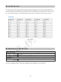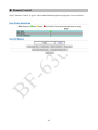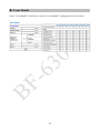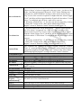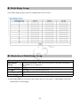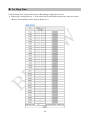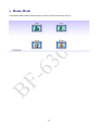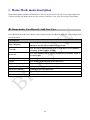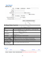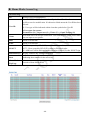
1
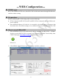
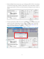
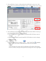
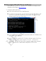
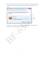
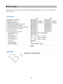
BF-631W WEB User Manual Applied for : 1.01.02,May/15/2013 (HW1.1) BF-631W Series: Web Ver1.1 Build Date:Jan/30/2013 【Contents】 -WEB Configuration- .....................................................................................................................1 WEB Logon .........................................................................................................................1 Preparation ...........................................................................................................................1 How to search BF-631W......................................................................................................1 How to login to BF-631W Web via web Browser ...............................................................5 Main Windows (Terminal Status)...............................................................................................7 Illustration of Terminal Status..............................................................................................8 User Administration .................................................................................................................10 Access Log.........................................................................................................................10 Illustration of Access Log .................................................................................................. 11 Auto Refresh Log...............................................................................................................12 Illustration of Auto Refresh Log ........................................................................................12 View User List ...................................................................................................................13 Illustration of User List ......................................................................................................14 Modify User Record...........................................................................................................15 Illustration of Modify User Record....................................................................................16 Add User ............................................................................................................................17 Illustration of Add New User .............................................................................................18 FP Sync. (Fingerprint Synchronization) ............................................................................19 Illustration of Fingerprint Synchronization........................................................................19 Terminal ...................................................................................................................................20 Terminal Status...................................................................................................................20 Illustration of Terminal Status............................................................................................21 Terminal Setup ...................................................................................................................22 Illustration of Terminal Configuration ...............................................................................23 Password Setup ..................................................................................................................26 Illustration of WEB Logon Setting/Entrance Password ....................................................27 System Log ........................................................................................................................29 Illustration of System Log .................................................................................................29 Clock Setup ........................................................................................................................30 Illustration of System Clock Setup ....................................................................................30 FKey Auto Trigger (Function Key)....................................................................................31 Illustration of IN/OUT Trigger Setup ................................................................................31 Function Key Setup............................................................................................................32 Illustration for Function Key Setup ...................................................................................32 Access Control .........................................................................................................................33 Time Set .............................................................................................................................33 Illustration of Time Set ......................................................................................................33 Time Zone Setup ................................................................................................................34 Illustration of Time Zone List ............................................................................................34 Illustration of Time Zone Information ...............................................................................35 Group List ..........................................................................................................................36 Illustration of Group List ...................................................................................................36 Illustration of Group Information ......................................................................................36 Holiday Setup.....................................................................................................................37 Illustration of Holiday Setup..............................................................................................37 Door Setup .........................................................................................................................38 Illustration of Door Setting ................................................................................................39 Set BF-50 Card...................................................................................................................42 Illustrations of BF-50 Card ................................................................................................42 Remote Control ..................................................................................................................43 Illustration of Door Status Monitoring & Security Bypass................................................44 Event Handle......................................................................................................................45 Illustration of Event Handle...............................................................................................46 Multi-Badge Group ............................................................................................................49 Illustration of Multi-Badge Group .....................................................................................49 Set Ring Time ....................................................................................................................50 Illustration for Ring Time Setup ........................................................................................51 Tools .........................................................................................................................................52 IP Camera...........................................................................................................................52 Illustration IP Camera ........................................................................................................52 Backup ...............................................................................................................................53 Illustration of Backup ........................................................................................................53 Restore ...............................................................................................................................54 Illustration of Restore ........................................................................................................54 Reboot ................................................................................................................................55 Illustration of Reboot .........................................................................................................55 Upgrade Firmware .............................................................................................................55 Illustration of Upgrade Firmware ......................................................................................55 Reset...................................................................................................................................56 Illustration of Reset............................................................................................................56 Home Mode..............................................................................................................................57 Home Mode menu description .................................................................................................58 Home mode: User Record - Add New User.......................................................................58 Home Mode: User List.......................................................................................................59 Home Mode: Access Log...................................................................................................60 Home Mode: Door Status Monitoring and Security Bypass..............................................61 Appendix Ⅰ .............................................................................................................................62 Appendix Ⅱ .............................................................................................................................65 Copyright @ 2011. All Rights Reserved. Document Version: 1.0《2011-05-24》 All trademarks and trade names are the properties of their respective owners. -WEB Configuration- WEB Logon BF-631W contains a HTTP server, thus BF-631W can link and connect through Web Browser, and then conduct setting. Preparation Before conducting BF-631W setting, make sure the following: ● PC has connected to BF-631W, and PC and BF-631W are situated in the same WAN with power supplied. ● If the default IP address (192.168.0.66 ) is occupied by else device, then it is a must to shut down that device first till the setting is over, and then allocate new IP address to BF-631W. How to search BF-631W 1、After installation of BF-631W and network cable is completed, use BF-631W ’s SEMAC Search to search all BF-631W in a certain LAN, or download SEMAC Search utility from CHIYU homepage www.chiyu-t.com.tw. Desktop icon as below: 2、Click SEMAC Searsh Picture icon, will display a window, as shown: -1- 3、While the SEMACSearch window shows up, it will display all BF-631W in LAN, and show its Terminal ID, Model Name, IP Address, Subnet Mark, Gateway, Mac Address, Software IP. Select particular BF-631W, then its related information will appear below the window, as shown: 4、The showed information of BF-631W can be revised directly in the window, the part can be modified: IP Address, Subnet Mask, Gateway, Software IP, Software Port, Terminal ID. After modification completed ( MAC Address can not modify ),click Alter then it will display the modified information, as shown: -2- 5、After modification, if want to confirm whether the modification is correct or not, click Refresh button to refresh and check information ( Fig-1 ), click Exit button to leave.(Fig-2) 6、After modification, the IP address of BF-631W has matched with its WAN, if want to get access into the Web of BF-631W , has two methods: (1) Open SEMAC Searsh, select and double click particular BF-631W, then to enter its webpage. (2) While the internet explorer opened, input BF-631W IP address to enter its webpage WINDOWS XP: 《Step 1》 Click WINDOWS XP my computer , Open Control Panel on the left side, please turn to traditional overview and select network link 《Step 2》 Click LAN, then select content, the link configuration will be shown, click Internet Protocol (TCP/IP) as left figure, then input the same setting as BF-631W, as right figure: -3- WINDOWS 7: 《Step 1》 Click Windows 7 icon, select click Alter Interface Card on the upper-left side. , open and search for, 《Step 2》 Click LAN link, select content, then the LAN settings will be shown, click Internet Protocol(TCP/IPv4), as left figure, click and input same setting as BF-631W, as right figure. -4- How to login to BF-631W Web via web Browser 1、Start Web browser ( ig: WIN 7 IE ), input BF-631W ’s IP Address, for example: use the default BF-631W IP Address: http://192.168.0.66 2、If connection failed, double check: If BF-631W installed and its power supplied properly To examine the LAN connection, operate PC function with “Start Runinput “cmd” instructoin to open MS-DOS commend mode, then test BF-631W connection, input command: ping 192.168.0.66, as shown below: If no message responded, it explains the connection has trouble or PC’s IP address is not match with BF-631W ’s IP address Set the PC’s IP address with BF-631W ’s IP address with same segment, if the PC uses fixed IP address, the address must be ranged in: 192.168.0.1 ~ 192.168.0.65 or 192.168.0.67 ~ 192.168.0.254 , thus it can be compatible with BF-631W ’s default IP address: 192.168.0.66, the “ Subnet Mask’s setting must be: 255.255.255.0 -5- 3、If the connection with BF-631W is successful, then it will display a message window for User name and Password, the default for user name and Password is: admin/admin, as shown below: 4、While the user name and password entered, a Web setting interface of BF-631W will be showed, enter it will then display a “ Quick Setup “ page. -6- Main Windows (Terminal Status) When installation has completed and connected with BF-631W, a “Main window” as below: -7- Illustration of Terminal Status ▼ Browse the Function Menu Bar at the left side of the Main Window by IE Browser User Administration 1. Look up all access logs 2. Extract Access log and Event record reports with TXT and Excel format Auto Refresh Log Instant Access to records display View User List 1. Display all user’s information 2. Modify “User List”, “Delete”, “Inactivate” and “Activate” user data Add User 1. Add single user account 2. Add batch user accounts Fingerprint Synchronization Setup a fingerprint synchronization method to be automatically or manually ▼ Access Log Terminal Display Terminal Status: Terminal ID, Model name, Firmware version…etc (Main Windows) Terminal Setup 1. Setup terminal principles like Terminal ID, Control Mode, Language display..etc (Terminal Setup” screen) 2. Terminal will be reboot after Terminal Setup has save Password Setup 1. Setup Administrator / User/ Sub-User web logon ID and Password. 2. Setup Common Password 3. Terminal will be reboot after password has reset System Log 1. Switch to the “System Log“ 2. Extract System logs to be Text or Excel format Clock Setup 1. Setup Network Time Server and Time Zone 2. Setup System Time Auto Function Key Setup Setup Function Key, Numeric Key, In/Out Time, up to 400 sets configurable Function Key Setup Setup Function Key, Numeric Key, Key definition, up to 400 sets configurable ▼ Terminal Status Access Control Time Set Setup Time Set , up to 255 sets configurable Time Zone Setup Setup Time Zone. Each Time Zone could define from Monday to Sunday and Holiday. Up to 120 Time sets configurable Group List Setup Group information. Up to 255 groups configurable Holiday Setup Setup Holiday information. Up to 100 holidays configurable Door Setup Setup Door access policies like: Exit button time zone, Lock Release time zone, Anti Pass Back. -8- Event Handle 1. Setup Event handle types, latch times...etc 2. Setup Event Alert Email address Multiple Badge Setup Multiple Badge combination. Up to 10 sets configurable, 2~3 legal users include to each combination Ring Time Setup 1. Setup Ring Time time set 2. Setup Ring tone lasting time 30 sets of Ring time can be configurable each day ▼ Remote Control 1. Display Door Status 2. Display Fire Alarm detection status 3. Remote Control door pulse open, pulse close, force open and force close. 4. Dismissed Event Alert 5. Activate or Inactivate Fire Alarm detection function Tools 1. Setup IP Camera IP address, types, ID and Password 2. Display captured image from IP Camera (latest picture) Backup Backup User list and Terminal information (User list is in TXT format only ) Restore Backup User list and Terminal information (User list is in TXT format only) Reboot System reboot Upgrade Firmware Firmware Upgrade Reset 1. Delete all data 2. System set to “Factory Default“ ▼ IP Camera Button ▼ Refresh Refresh the WEB Status. Home Mode Switch to “Home Mode” menu -9- User Administration Access Log Select “Access Log” on the Main Window, you’ll see the “Access Log” screen as following picture: -10- Illustration of Access Log ▼ ▼ Access Records Illustration by Columns No. Serial Number of Access Logs User ID will be showed for the user who has access the door. By clicking “User ID” will direct current screen to “User Record ”page to “Modify User Record” ( picture 4). Should it be not connected, it means the User ID information of the User ID has been deleted. * The figure in the parentheses( ) after the “User ID” means the user’s level as 1~10. A Name registered for the User to get IN/OUT. When the registered User Name information without “Name”, this column will be blank. Date A Date allowed for the User to get IN/OUT. Time A Time allowed for the User to get IN/OUT. IN: Access by WEBPASS IN/OUT OUT: Access by Wiegand Reader ※ APB level will be shown followed the IN/OU Door No. It stands for the Door Number Controlled By BF-631W Show up the relative IN/OUT records automatically as Anti-Duress, Fire Note Alarm......etc. The First Page Back to the 1st IN/OUT records page. The Former 10 Forwarding 10 pages from the current IN/OUT records page. Pages 1 2 3…N Page Change to any IN/OUT records page assigned. The Latter 10 Pages Backwards 10 pages from the current IN/OUT records page. The Last Page Fly to the last IN/OUT records page directly. Query and Export 1. User:Check the user, can search the user records, and export the file out Type 2. Event:Check the Event, can search the Event records, and export the file out 1. Single:Can only query / export a single user's access to records or 5 User ID or Card records of the event within an event Number 2. All:Can query / export all of the Access record or record of events StartDate/End Date Select the date by “Drop Down Menu”. Enter user ID to query Searchable/Export Card No Enter Card No to query Searchable/Export Event Button Click event Enter Event type query 5 maximum query event types. ▼ User ID Search Export Set the Search Requirement Click button to Search access records to demonstrate Requirement. Set the Export Requirement Click button to Export requirement TEXT or Excel file. -11- Auto Refresh Log Select “Auto Refresh Log” on the Main Window, there’ll be “Auto Refresh Log” screen as the following picture: ▼ Illustration of Auto Refresh Log Auto Refresh Log No. Serial Number. User ID Instant Display Access records User ID. User Name Instant Display Access records User Name. Date Instant Display Access records user enter/out date. Time Instant Display Access records user enter/out Time. IN/OUT Instant Display Access records user IN/OUT Log Door Instant Display Door Note. Show up the relative IN/OUT records automatically as Anti-Duress, Fire Alarm......etc. -12- View User List Select”View User List” on the Main Window, you’ll see the “User List ” screen as following picture: -13- Illustration of User List ▼ ▼ ▼ Search User By “User ID” Select “User ID” and enter “User ID” in the textbox to search. By “Card No.” Select “Card No.” and enter “Card No.” in the textbox to search. By “Employee ID” Select “Employee ID” and enter “Employee ID” in the textbox to search By “User Name” Select “User Name.” and enter “User Name” in the textbox to search. Click button ”GO” Start to search. Steps: 1、Enter “User ID”, “Card No.” or “User Name” in the textbox 2、Click button “GO” to search User List Serial Number. Tick the box before the “Serial Number” and Click the button of “Activate” , “Deactivate” or “Delete” to manage the No. authorization of “Activate” , “Deactivate” or “Delete” for selected users, multi-selection is allowed. Display User’s ID. By clicking“User ID” to connect to “Modify User User ID Record” page for modification Employee ID Display Employee ID User Name Display User Name Types of the system users. Whenever the “User Type” is set up in the screen of “Modify User User Type Record”, this page will display Normal User (N), Super User(S), Visitor(V), Guard Touring(G) Display user’s authorization status. Green light displays user’s Active authority is activated, Grey light means user authority is inactived When the user’s Fingerprint registered, this column will be with Green F Light. When the user’s Personal Password registered, this column will be with P Green Light. C When the user’s card registered, this column will be with Green Light. Bypass Level Display the user’s Bypass time zone level from L1~L10. The First Page Back to the 1st page of “User List”. The Former10 Forwarding 10 pages from the current “User List” page. pages 1 2 3…N page Change to any “User List” page assigned. The Latter 10 Backwards 10 pages from the current “User List” page. pages The Last Page Fly to the last “User List” page directly. Button Activate Activate the User’s authorization. Deactivate Deactivate the User’s authorization. Delete Delete the User’s information registered. -14- Modify User Record Select "Modify User Record" on the Main Window, you'll see the " User Record" screen as following picture: -15- ▼ Illustration of Modify User Record User Record User ID Card No Employee ID Name Expire Date Check Effective From ~ To Status User Type Group Bypass TZ Level Personal Password Input Card number by manually input or read by card decoder Input Employee ID within 10 English characters or 3 words for Chinese User’s Name, 10 characters at the most Tick the box of “Enable” or “Disable” the user’s expiry date control. When “Enable” the “Expire Date Check”, you must enter the period of dates. The” Drop Down Menu” offers you the options of Year/Month/Date/Hour/Minute. Tick the box of “Activate” or “Deactivate” for user’s authority Card Types of the User. The "Drop Down Menu" will list all cards for Normal User/ Super User/ Visitor/ Guard Touring. The Respective definitions are as below : Normal User: General authority only Super User Card : Not constrained by APB (Anti Pass Back) policy Visitor Card: You may manage the visitors easily by setting the Visitor Card's Expiry Dates. Guard Touring: When the Guard Touring card senses the door, only the Logs will be kept but no door-open function. Each user can be assigned to 4 different groups. All the group names existed will be automatically listed out by the "Drop Down Menu "for your choice. "Free Time Group "is a "Default Group". 1. User’s bypass time zone level is equal to Door setup’s bypass time zone: User access door by the card 2. User’s bypass time zone level is higher than door setup’s bypass time zone: User access door by the card 3. User’s bypass time zone is lower than door setup’s bypass time zone: User should follow Door Setup bypass time zone access policy to access the door. 4~8 digits password combination is required. For command mode: User may use #UID#P# to input personal password Reconfirm Personal Password ▼ Personal Confirm Button Previous User ID number can be create within 1~4294967295 or User ID couldn’t be save if ID is exceeding the number Save Delete Next Modify previous user record. Save the modified user record. Delete existing user record. Modify next user record. -16- Add User Select “Add User” on the Main Window, you’ll see the “User Record” screen as following picture: -17- ▼ Illustration of Add New User User Record REG User ID Card No Employee No Name Expire Date Check Effective From ~ TO Status User Type Group Bypass TZ Level Personal Password Display current fingerprint template capacity ▼ Personal Confirm Fingerprint Template capacity Button Save 1、Single: Only one user can be registered each time. 2、Continuous: It allows you to register 1~20000 users in a time by input user account quantity in the text box and only a chain serial numbers is supported User ID can be within 1~4294967295 or User ID couldn’t be save when the ID is exceeding 4294967295 Manually input card number or by read by card decoder Input employee number, 10 English characters is acceptable or 3 words in Chinese only User’s Name, max. 10 characters allowed. Tick the box of “Enable” or “Disable” the user’s expiry date control. When “Enable” the “Expire Date Check”, you must enter the period of dates. The” Drop Down Menu” offers you the options of Year/Month/Date/Hour/Minute. Tick the box of “Activate” or “Deactivate” for a authorization to the user. Card Types of the User. The "Drop Down Menu" will list out cards for Normal User, Super User, Visitor, Guard Touring. The Respective definitions are as below: Normal User:General access authority Super User Card:Not constrained by the limitation of APB ( Anti Pass Back). Visitor Card:You may manage the visitors easily by setting the Visitor Card's Expiry Dates. Guard Touring:When the Guard Touring card senses the door, only the Logs will be kept but no door-open function. Each user can be assigned to 4 different groups. All the group names existed will be automatically listed out by the "Drop Down Menu "for your choice. "Free Time Group "is a "Default Group" L1~L9 bypass time zone provide. 1. User’s bypass time zone level is equal to door setup bypass time zone l: User may access door by the card. 2. User’s bypass time zone level is higher than door setup’s bypass time zone: User may access door by the card 3. User’s bypass time zone level is lower than door setup’s bypass time zone: User’s may access door by door setup’s bypass time zone authority. 4~8 digits combination is required. For commend mode, user may registry password by pressing #UID#P# Reconfirm Personal Password. Save User Records. -18- FP Sync. (Fingerprint Synchronization) By fingerprint synchronization function hyperlink to get into Fingerprint Synchronization windows directly: ▼ Illustration of Fingerprint Synchronization Auto synchronization time Manually synchronization 1 or many user’s fingerprint templates is selectable to be update to BioSense (Suitable when connecting BioSense) ▼ Time Setup synchronize time as “Minute : Second ( in Base-24)” for automatically fingerprint synchronization (Suitable when connecting with BioSense fingerprint reader) Setup Setup Save data -19- Terminal Terminal Status Select ”Terminal Status” on the Main Window, you’ll see the “Terminal Status ” screen for Logon. It will display current Terminal Status and relative information of WEB setup as following picture: -20- ▼ Illustration of Terminal Status TERMINAL STATUS Product Name Model Number of BF-631W Serial No. Serial Number of BF-631W Firmware Version Firmware and Hardware Version of BF-631W System Time System Time of BF-631W Terminal ID (MAC Address) Terminal ID and MAC address of BF-631W IP Address IP address of BF-631W Subnet Mask Subnet mask of BF-631W Default Gateway Default Gateway address of BF-631W Primary DNS Primary DNS address of BF-631W Listen Port/Software IP(Status) BF-631W and software communication Port number and Software IP address (status between WebPass and software: Online or Offline) WEB Management Port BF-631W WEB communication port number Registered User Registered user numbers of BF-631W Available User Capacity Available Capacity of BF-631W to register users; Available user number(s) to be registered= Sum (20000)-Registered user(s) Registered Fingerprint Display registered fingerprint templates quantity Available Fingerprint Capacity Available Fingerprint capacity of BF-631W to register users Access log/System Log Count The Sum from access and system logs of BF-631W Control Mode Control mode of BF-631W is Controller (WG34) Anti-Pass-Back(Tolerance Timer) Enable or Disable the BF-631W APB (Anti Pass Back) function and Tolerance Time setup Anti-Duress Enable or Disable the BF-631W function of Anti Duress. Next BF-631W (Status) Display IP address of BF-631W and On-line or Off-line status -21- Terminal Setup Select "Terminal Setup" on Main Window, you'll see the "Terminal Configuration "as following picture: -22- ▼ Illustration of Terminal Configuration Terminal Configuration Terminal ID For setting the Terminal ID of BF-631W. Default =1, max. 65535, not allowed to duplicated. IP Address For setting the IP Address of BF-631W. Subnet Mask For setting the Subnet Mask of BF-631W. Default Gateway For setting the Default Gateway of BF-631W. ▼ DNS Server IP Address For setting the DNS Server IP Address of BF-631W . Default DNS Server IP Address is 168.95.1.1. Display Title ▼ Set up a string of word to be display on the BF-631W LCD Software Listen Port For setting the TCP Port of the Software to communicate with BF-631W. Default TCP Port is 2000. Software IP For setting the Software IP to communicate with BF-631W. Default Software IP is 0.0.0.0. ▼ TCP Port(for Software) Web Language Select ” English” as system language from the pull down menu, the WEB page of BF-631W will be switched to “English” interface . Chs Select ”Chs” as system language from the pull down menu, the WEB page of BF-631W will be switched to “Simplified Chinese” interface . Others Select ”Chs” as system language from the pull down menu, the WEB page of BF-631W will be switched to “Traditional Chinese” interface. ▼ English Anti Pass Back Tick this circle to enable the “APB”(Anti Pass Back) function. Disable Tick this circle to disable the “APB”(Anti Pass Back) function. Tolerance Timer Set up the restored time back to original setting after the “APB” triggered. The unit of time is “minute” and the max. Value is “65535”. If the value is “0”, then it will never be restored until you disable the “APB” by manual. ▼ Enable Anti Duress Tick this circle to enable the “Anti Duress” function. Disable Tick this circle to disable the “Anti Duress” function. Password Set your password of “Anti Duress”, default value = 9, max. 3 digits. ▼ Enable WEB Management Port Http Port Set your WEB port for BF-631W , default value=80. -23- ▼ Next BF-631W (for APB only) ▼ IP Address Set your IP address for Next BF-631W but only available for the structure of multiple BF-631W applications. Whenever this IP for next BF-631W is set up, all the levels settings of original BF-631W will be synchronized to next BF-631W Fast-Registry mode Inactive Select Inactive to disable Fast-Registry mode ▼ Active Fast-Registry mode will be active when selecting Active Note: Disable Fast-Registry mode is necessary after new user card is registered Voice indication mode Select Active to turn on voice indication mode when card is read Inactive Select Inactive to turn off voice indication mode when card is read ▼ Active Fingerprint verification level ▼ Default value is Auto Normal ( Note: Default value is recommended ) Illegal Fingerprint verification Keeps log(s) for illegal fingerprint(s) Inactive Keeps no log(s) for illegal fingerprint(s) ▼ Active External Reader Access log direction will be indicating “IN” when select “IN” (Reader is installed at OUTSIDE of a door) OUT Access log direction will be indicating “OUT” when select “OUT” (Reader is installed at INSIDE of a door) ▼ IN WIEGAND INPUT 34 Bits Display card number with Wiegand 34 bit format (4 bytes). Custom format is acceptable 26 Bits Display card number with Wiegand 26 bit format (3 bytes). Custom format is acceptable 12 selectable fingerprint verification security levels *(Recommend NOT change from system default : Auto Normal) Auto Normal Default Fingerprint Verification Security Level (Recommend NOT change) ▼ 1/10,000 ~ 3/100,000,000, Auto Secure Connection with Software Realtime (Client) Establish Internet connection between software and terminal by using “Realtime (Client)” mode. Terminal (BF631W) is in passive operation mode. Custom modification is acceptable Passive(Server) Establish Internet connection between software and terminal by using “Passive (Server)” mode. Terminal (BF631W) is in active operation mode. Custom modification is acceptable -24- ▼ Double Clock In Control Disable Enable Disable the function Not allow double clock in within a certain time. When timer for double clock in time has enabled to be 10 seconds, then the clock in time between first time and second time should be 10 seconds. Note : 0 is not acceptable for double clock in ▼ Card no. Display Display registry card number as Decimal format Hexadecimal Display registry card number as Hexadecimal ▼ Decimal Card Format Based on original card number (Serial number on the “Block 0”) Facility Code+ID Display 10 numeric card format: First 5 numbers is for the factory facility code, and later 5 numbers is for the identification code ▼ Raw Data Function Key Trigger Mode Manual FKey Mode ▼ Auto FKey Mode System will direct to latest action to the function key. For example: User A pressed F1 (eg. Break Out) and then User B is no needed to press F+1 (eg. for Break Out) until someone pressed other Function Key (eg. F+2 for Break In). For system has memorized the latest input parameter System will automatically detect the definition setup on “IN/OUT Trigger Setup” and “Function Key Setup” for Auto FKey Mode Button Save Save the Terminal Configuration Settings -25- Password Setup Select ”Password Setup” from main menu for setup “WEB Logon Setting/Entrance Password ”. Referring to the following picture: -26- ▼ Illustration of WEB Logon Setting/Entrance Password WEB Logon Setting Administrator User Name Input the required Administrator’s logon user name for WEB management, max. 47 characters, default value: “admin”. Administrator Password Input the required Administrator’s logon password for WEB management, max. 35 digits, default value: “admin”. Operator User Name Input the required Operator’s logon user name for WEB management, max. 47 characters, default value: “user”. Operator Password Input the required Operator’s logon password for WEB management, max. 35 digits, default value: “user”. User’s User Name Input the required User’s logon user name for WEB management, max. 47 characters, default value: “user0”. User Password Input the required User’s logon user name for WEB management, max. 35 digits, default value: “user0”. ▼ The Administrator, Operator and User have their respective authorizations, referring to the following “Authorization Table”. Entrance Password Setup a common password for all users or keep it as blank to disable common password authority. Default value: “1234” Command mode password Using Command mode password to access BF-631W terminal. Pressing 111111 (6 digits) pressing “F1F1” to enter to main menu ▼ Common Password Button Save Save the Password Setting. -27- Authorizations Table ( “●” = Access Permission ) WEB Function Administrator User Name: admin Password: admin Operator User Name: user Password: user User User Name: user0 Password: User0 Upgrade Firmware ● Password Setup ● Terminal Setup ● Door Setup ● Event Handle ● Reboot ● Clock Setup ● Reset ● Upgrade Firmware ● Password Setup ● Terminal Setup ● User Data ● ● Time Set ● ● Time Zone Setup ● ● Group List ● ● Holiday Setup ● ● Lift Setup ● ● Multi Badge Group ● ● Remote Control ● ● Access Log ● ● ● View User List ● ● ● Terminal Status ● ● ● System Log ● ● ● IP Camera ● ● ● -28- System Log Select ”System Log” on the Main Window for checking system log, or export system log report as TEXT or Excel format: ▼ Illustration of System Log System Log No. Serial Number of the log. Date Date of the log Time Time of the log Description Description of the System Operation records. Export TXT Export TXT File Export XLS Export XLS File ※ Max. log capacity is 1536 entries for authorized person(s) checking only, no logs export provided. -29- Clock Setup Select "Clock Setup" on the left side of the Main Window, you'll see the "System Clock Setup" screen, referring to the following picture: ▼ Illustration of System Clock Setup Time Server Disable Tick this circle to shut up the Time Server network connection. Enable Tick this circle to start the Time Server network connection. Time Zone The “Drop Down Menu” offers you all the Time Zones available up to your option, default time zone : (GMT)England. “SAVE” button Save the Time Server Settings and adjust the time. When enable the “Time Server”, please key in the IP address or http:// of the “Time Server”. Then select the required Time Zone and Save it to connect the “Time Server” for a time adjustment. New Date New Time SAVE (button) The date of networked PC computer. You may adjust the date to your requirement as the format of “mm/dd/yyyy”. The date of networked PC computer. You may adjust the time to your requirement as the format of “hh:mm:ss”. Save the configuration of this page and upgrade the date/time for the networked PC computer. -30- FKey Auto Trigger (Function Key) Configure IN/OUT trigger setup to start the automatically Function Key service: ▼ Illustration of IN/OUT Trigger Setup Configure Time Set for IN/OUT Trigger Setup Function Key Provide 4 sets of function keys F1~F4, select one from the pull down menu. Numeric Key Provide 0~9 numeric keys for extending function key sets up to 400 sets, selecting numbers from the pull down menu. IN- - -OUT IN: Input a start time / OUT: Input a finish time ▼ Note: IN/OUT trigger time set preset for function key is important when performing IN/OUT records and displaying on BF-631W LCD. When user is manually pressed the hardware function key, the IN /OUT indication will be displaying on the access record. When user is not pressed the function key during the preset time, then IN and OUT indication will be display the combination of the function key (when FKey presets with function key name then display with function key name, or nothing preset for the function key then IN/OUT records will be display with NONE) Button Delete Delete the preset time set Set Add new time set -31- Function Key Setup Function Key Setup window is as below: ▼ Illustration for Function Key Setup Function Key Setup Provide F1~F4 function key selection Numeric key Provide 0~9 function key selection Definition Input function key with name ▼ Function key Button Delete Delete preset function key Set Add new function key Note : Maximum Function key combination can be 400 sets -32- Access Control Time Set Select and Click “ Time Set ” on the left side of the Main Window, you’ll see the “Time Set” configuration screen, referring to the following picture: ▼ Illustration of Time Set Time Set List Time Set List It will display all the configured time set(s). 2 System Default Time sets are : 00:00~00:00 and 00:00~23:59 Time Set Select a time set serial number for the time set from the pull down menu. Maximum Time Set can be. 255 sets. System built-in values are “000” and system default serial number for time set is “000” and “001” Input a time set period, for example : 8:00am to 17:00pm as one period, then ▼ From ~ To Button DELETE Delete an existing “Time Set”. SET Add a new “Time Set”. -33- Time Zone Setup Select and Click "Time Zone Setup" on the left side of the Main Window, you'll see the "Time Zone List" screen referring to the following picture: ▼ Illustration of Time Zone List Time Zone List Display all the Time Zone(s) existing. Click the Time Zone name(indicated as the Time Zone Name example) to enter its Time Zone Information Screen. Time Zone ID Select your Time Zone Serial Number from the “Drop Down Menu”, system built-in numbers as “000” and “001”, max. 120 Time Zones allowed. Time Zone Name Click the name of Time Zone ( for example : 2, as below picture) to enter the ”Time Zone Information” screen for modification. ▼ Time Zone List Button DELETE Delete an existing Time Zone. SET Enter the Time Zone Information screen. -34- Here is an example of “Time Zone Information” screen to show how to set the daily door access and card punching authorized Time Set from Monday to Sunday and Holidays: ▼ Illustration of Time Zone Information Time Zone Information Setting Time 1 ~ Time16 Each day from Monday ~Sunday and Holiday is allowed 16 time sets. However, you have to make some Time Sets on the “Time Set” screen in advance for the options here, otherwise only 2 default system Time sets can be chosen, referring to the following illustration: ▼ Weekday (Day) The “Drop Down Menu ”offers you options from Monday to Sunday and Holiday. Steps : “SET” the “Time Set” on “Time Set” screen Select your weekday Choose your time set(s) of the time zones. Button Save Save the“ Time Zone Information”. Cancel Cancel or Modify the “Time Zone Information”. When the “ Time Zone Setup “ completed, please click the “Time Zone Name ”to enter to “Time Zone Information” screen. -35- Group List Select and Click ”Group List ” on the left side of the Main Window, you’ll see the “Group List ” screen referring to the following picture: ▼ Illustration of Group List Group List Group List Group ID ▼ Button Delete Set Display all the Groups configured. Click the Group’s name to enter its “Group Information ” Select your “Group ID” by serial number, default values : 000、001. The ”Drop Down Menu ”offers you all the serial number of Group ID as options, max. 255 groups allowed. Delete a Group ID. Enter the “Group Information” screen. Below Group Information screen is to configure door(s) with a specific time zone ID, referring to the following picture: ▼ Illustration of Group Information Allowed Door Door ▼ Tim Zone ID Button Save Cancel Tick the box of Door (number) means a certain group users have authorized to access the door during the preset time, otherwise it is prohibited. Display preset time zone information from the pull down menu Save the “Group Information”. Cancel or Modify the “Group Information” -36- Holiday Setup Select and Click ”Holiday Setup” on the left side of the Main Window, you’ll see the “Holiday setup” screen referring to the following picture: ▼ Illustration of Holiday Setup Holiday Setup Select a month from the “Drop Down Menu”. Date Select a date from the “Drop Down Menu”. ▼ Month Button Set Add a new Holiday. Delete Delete a Holiday. -37- Door Setup Select and Click ”Door Setup” on the left side of the Main Window, you’ll see the “Door Setting” screen as below: -38- ▼ Illustration of Door Setting Door Setting Set up door’s bypass time zone as L9 (Default: Deactivate). Verification of first entry to the door must be using Administrator’s fingerprint. After admin (L9) First Admin fingerprint has been verified, all users may access the door by user’s card or fingerprint or password. FP (IN) Time ※ When door’s bypass time zone level is set to lower or equal to user’s Zone bypass level then user may access the door by user’s card or fingerprint or password. Set up door’s bypass time zone as L8 (Default: Deactivate). Before set up L8 time zone to a door, it should be firstly composed a multiple badge work sheet at Multi Badge Group configuration menu. L8 bypass time zone provides (L8) Multiple FP maximum 10 multiple FP time zone groups, and each group may consist of 2~3 registered users. No verification order is limited. Time Zone ※ When door’s bypass time zone level is set to lower or equal to user’s bypass level then user may access the door by user’s card or fingerprint or password. (L7) Multiple Badge Time Zone Set up door’s bypass time zone as L7 (Default: Deactivate). Before set up L7 time zone to a door, it should be firstly composed a multiple badge work sheet at Multi Badge Group configuration menu. L7 bypass time zone provides maximum 10 multiple badge time zone groups, and each group may consist of 2~3 registered users. No verification order is limited. ※ When door’s bypass time zone level is set to lower or equal to user’s bypass level then user may access the door by user’s card or fingerprint or password. (L6) Card + FP + Personal Password Time Zone Set up bypass time zone for the door as L6 mentioned (Default: Deactivate). User may access the door by Card + Fingerprint + Password without verification order. To assure user has properly verified according to L6 bypass time zone requested, BF-631W hardware LCD will be displaying which verification item is needed. (Suggest users follow the LCD instruction) ※ When door’s bypass time zone level is set to lower or equal to user’s bypass level then user may access the door by user’s card or fingerprint or password. -39- (L5) FP + Personal Password Time Zone (L4) Card + Personal Password or Card + FP Time Zone (L3) Personal Password or FP Time Zone (L2) Card Only Time Zone (L1) Card or Password or FP Time Zone Set up bypass time zone for the door as L5 mentioned (Default: Deactivate). User may access the door by Fingerprint + Password without verification order ※ When door’s bypass time zone level is set to lower or equal to user’s bypass level then user may access the door by user’s card or fingerprint or password. Set up a bypass time zone for the door as L4 mentioned (Default: Deactivate). User may access the door by Card+ Password or Card+ Fingerprint without verification order. BF-631W LCD will indicate users to press * to start verification for 1:1 or input personal password. ※ When door’s bypass time zone level is set to lower or equal to user’s bypass level then user may access the door by user’s card or fingerprint or pa ssword. Set up a bypass time zone for the door as L3 mentioned (Default: Deactivate). User may access the door by input personal password (command by #UID#P#), or verify fingerprint. ※ When door’s bypass time zone level is set to lower or equal to user’s bypass level then user may access the door by user’s card or fingerprint or password. Set up a bypass time zone for the door as L2 mentioned (Default: Deactivate). User may access the door by user’s card. ※ When door’s bypass time zone level is set to lower or equal to user’s bypass level then user may access the door by user’s card or fingerprint or password. Set up a bypass time zone for the door as L1 mentioned (Default: Anytime). User may access the door by user’s card or fingerprint or personal password (#UID#P#) or common password. ※ When door’s bypass time zone level is set to lower or equal to user’s bypass level then user may access the door by user’s card or fingerprint or password. Set up a Lock Release time zone at the door (Default: Deactivate). All users Lock Release Time Zone may access the door without verification. When First Card is selected as Needed, then the Lock Release Time Zone will only be activated after scan by a legal card. Exit Button TZ Set up an Exit Button time zone at the door. Supporting only OUT direction. (Default: Any Time). Anti Pass Back Level Set up an Anti Pass Back Level at both “IN” and “OUT” direction of a Door. APB level is allowed to be configured within 0~255. Lock Delay Time Set up the “Lock Release Time” , default as 10 seconds. -40- Door Open Delay Time Set up “Door Open Delay Time” , default as 10 seconds. Access Log Ignore or Record the access logs Door Sensor Mode Set up door sensor mode to be N/A or Normal Open/Close. Default is N/A. When Normal Open/Close is selected, door status will display door sensor circuit Short or Open. Door Relay Energized There are 3 options for activating Door Lock relay after verification is done: None:No trigger door lock relay 1 Relay:Trigger door lock relay from BF-631W 2 Relay:Trigger door lock relay from BF-631W and also trigger other relays. For BF-20 and BF-50 status: 1 Relay:Without BF-20/BF-50 installed, trigger another relay on BF-631W 2 Relay:With BF-20/BF-50 installed, trigger relay 2 only ※ Check up for Hard alarm & Soft alarm on Event Handle should not be ▼ overlapping. Button Set BF-50 Card Input 50 sets of card numbers to BF-50. When main controller is disconnected to BF-50, BF-50 will check the card number with the input card number list to open the door. Update BF-50 Card Input card number to BF-50 then tap the update button to update card numbers to BF-50 -41- Set BF-50 Card To secure door will be opened when any disconnections happened to current system, BF-631W provides alternative mechanism to open the door by presetting 50 sets legal cards into BF-50 relay box. Select” Door Setup” on the Main Window, then click “Set BF-50 Card” button as below: ▼ Illustrations of BF-50 Card BF-50 Setting Total 50 card numbers can be set to the BF-50 Card No Enter card number for BF-50 ▼ NO Button Set Save card numbers only ※ Press “Upgrade to BF-50” button to update the card numbers we Set to BF-50. -42- Remote Control Select” Remote Control” to get to “Door Status Monitoring/Security Bypass ”screen as below: -43- ▼ Illustration of Door Status Monitoring & Security Bypass Door Status Monitoring BF-50 Status Displaying BF-50 update status. x means no equipped with BF-50 Fire Alarm Detection Display if the “Fire Alarm Detection ”enabled or not. ▼ Door Status Displaying update door status. No light means BF-631W device has no response. Green light means BF-631W is connected and the door is closed normally. Yellow light means door is opened. Red light means door sensor circuit short/open/intruded/or door open too long Security Bypass Status There are three “Security Bypass Status” for the door : Normal/Force Open/Force Close . Pulse Open Door Click Pulse Open Door button to open the door remotely. The function only works when the Security Bypass status is Normal. Force Close Click Force Close button to make a force close to the door remotely. Hence the status of the door will display Force Close and the door will not be opened by any valid cards. ※Force Close function can only be dismissed by pressing Back to Normal key. Back to Normal Click Back to Normal button to recover door status to be normal Force Open Click Force Open button to make a force open to the door remotely. Hence the state of the door will display “Force Open “and the door will stay at “Lock Release” status until pressing Back to Normal key. Fire Alarm Detection ON Click the button to activate the “Fire Alarm Detection” function and the door status will be display as “ON”. Fire Alarm Detection OFF Click the button to deactivate the “Fire Alarm Detection” function and the door status will display as “off”. Alarm OFF Click Alarm off button to dismissed the alarm -44- Event Handle Select” Event Handle” from menu to enter to “Event Handle” configuration screen as below: -45- ▼ Illustration of Event Handle Event Type 1. It will be listed in the “Drop Down Menu”. When it’s selected and the user unregistered, one unregistered record will be shown on the “ Access Log ”screen (referring to the sample as below); if the event level equal to or higher than the “Alarm Trigger Level”, the Relay will be triggered and the E-mail will alert when “ E-mail Alerts ”is configured and one alert Unregistered User e-mail will be sent out. 2. When the “Latched Time : 0”, the alert can only be lifted/stopped by clicking “ Alarm OFF ”button on the “Door Status Monitoring/Security Bypass” screen of “Remote Control” function, default level = 0, referring to the below picture : 1. It will be listed in the “Drop Down Menu”. When it’s selected and the user card has been deactivated then a Deactivated status will be recorded to Access Log screen. If Event Handle level is equaled to or higher than the “Alarm Trigger Level”, the Relay will be triggered then sent and alert Deactivated User E-mail to the account which has been configured. 2. When the “Latched Time : 0”, the alert can only be lifted/stopped by clicking “ Alarm OFF ”button on the “Door Status Monitoring/Security Bypass” screen of “Remote Control” function, default level = 0. 1. It will be listed in the “Drop Down Menu”. When it’s selected and the user’s “Group” setting is different than the Door’s group settings, then a“Disallowed door” message will be recorded on the “Access Log ”screen; if the event handle level is equaled to or higher than Not Allowed Door the“Alarm Trigger Level”, the Relay will be triggered and an E-mail will be sent out if any email account has been configured. 2. When the “Latched Time : 0”, the alert can only be stopped by clicking “ Alarm OFF ”button on the “Door Status Monitoring/Security Bypass” screen of “Remote Control” function, default level = 0. 1. It will be listed in the “Drop Down Menu. When it’s selected and the user’s Time Zone Group setting is different from the Door Group Time Zone settings, one Open Time Error message will be recorded on the Access Log ”screen; If the event handle level is equaled to or higher than Time Zone Violation the“ Alarm Trigger Level”, the Relay will be triggered and an E-mail will be sent out to the account which has been configured 2. When the “Latched Time : 0”, the alert can only be stopped by clicking Alarm OFF button on the “Door Status Monitoring/Security Bypass” screen of “Remote Control” function, default level = 0. -46- Expired User Anti Pass Back Violation Door open too long Tamper Switch Breakdown Door Intruded 1. It will be listed in the “Drop Down Menu”. When it’s selected and the user’s “Expiry Date” overdue one “EXPIRED ”message will be recorded on the Access Log ”screen. If the event handle level is equaled to or higher than the“ Alarm Trigger Level, the relay will be triggered and an E-mail will sent to an email account which has been pre-configured. 2. When the “Latched Time : 0”, the alert can only be stopped by clicking “ Alarm OFF ”button on the “Door Status Monitoring/Security Bypass” screen of “Remote Control” function, default level = 0. 1. It will be listed in the “Drop Down Menu”. When it’s selected and the doors with “Anti Pass Back Level ”configuration, one “Anti_PB Rej ”message will be recorded on the Access Log ”screen. If the event handle level is equaled to or higher than the“ Alarm Trigger Level”, the Relay will be triggered and an alert E-mail will be alert to an account which has been pre-configured. 2. When the “Latched Time : 0”, the alert can only be stopped by clicking “ Alarm OFF ”button on the “Door Status Monitoring/Security Bypass” screen of “Remote Control” function, default level = 0. * Only 1 Door (2 way) is supported 1. It will be listed in the “Drop Down Menu”. When it’s selected and the door closes over the time set after the user’s card flashed, one “Open too long ”message will be recorded on the Access Log ”screen. If the event handle level is equaled to or higher than the“ Alarm Trigger Level”, the Relay will be triggered and an alert E-mail will be alert to an account which has been pre-configured. 2. When the “Latched Time : 0”, the alert can only be lifted/stopped by clicking “ Alarm OFF ”button on the “Door Status Monitoring/Security Bypass” screen of “Remote Control” function, default level = 0. 1. It will be listed in the “Drop Down Menu”. When it’s selected and the device is opened forcibly, one “CASE OPENED”message will be shown on the Access Log ”screen. if the event level equals to or higher than the“ Alarm Trigger Level”, the Relay will be triggered and the E-mail will alert when “ E-mail Alerts ”is configured and one alert e-mail will be sent out. 2. When the “Latched Time : 0”, the alert can only be stopped by clicking “ Alarm OFF ”button on the “Door Status Monitoring/Security Bypass” screen of “Remote Control” function, default level = 0. 1. It will be listed in the “Drop Down Menu”. When it’s selected and the door is accessed forcibly and abnormally, one “ DOOR INTRUDED ” message will be shown on the Access Log ”screen ; if the event level equals to or higher than the“ Alarm Trigger Level”, the Relay will be triggered and the E-mail will alert when “ E-mail Alerts ”is configured and one alert e-mail will be sent out. 2. When the “Latched Time : 0”, the alert can only be stopped by clicking “ Alarm OFF ”button on the “Door Status Monitoring/Security Bypass” screen of “Remote Control” function, default level = 4. -47- Duress Alarm On Fire Alarm On Latched Time 1. It will be listed in the “Drop Down Menu”. When it’s selected and the “Duress Alarm ”of a door is triggered by the user ( note : you have to key in the “Anti Duress Password” then press “ENT ”before flashing users card) then an “ANTI DURESS” message will be shown on the Access Log ”screen; if the event level equals to or higher than the“ Alarm Trigger Level”, the Relay will be triggered and the E-mail will alert when “ E-mail Alerts ”is configured and one alert e-mail will be sent out. 2. When the “Latched Time : 0”, the alert can only be stopped by clicking “ Alarm OFF ”button on the “Door Status Monitoring/Security Bypass” screen of “Remote Control” function, default level = 4. 1. It will be listed in the “Drop Down Menu”. When it’s selected and if the “Fire Alarm ”is triggered, one “FIRE ALARM” message will be shown on the Access Log ”screen; if the event level equals to or higher than the“ Alarm Trigger Level”, the Relay will be triggered and the E-mail will alert when “ E-mail Alerts ”is configured and one alert e-mail will be sent out. 2. When the “Latched Time : 0”, the alert can only be stopped by clicking “ Alarm OFF ”button on the “Door Status Monitoring/Security Bypass” screen of “Remote Control” function, default level = 5. The “Latched Time” can be set up to 65535 seconds. When the “Latched Time : 0”, means the latched status will never be restored until the alert be stopped by manually clicking “ Alarm OFF ”button on the “Door Status Monitoring/Security Bypass” screen of “Remote Control” function. Event Handle Types Hard Alarm Soft Alarm 1 Soft Alarm 2 IP Camera ▼ Preset one or many event type(s) to trigger BF-631W I/O relays Preset one or many event type(s) to trigger BF50 Relay No.2 Preset one or many event type(s) to trigger BF50 Relay No.3 Preset one or many event type(s) to trigger IP Camera to take snap shot Preset one or many event type(s) to trigger email alarm sends to certain E-Mail Alarm email recipients Event Handle - E-mail Alerts Location Enter the equipment name or location for alarming. SMTP Mail Server Enter the Mail Server address of sending Alarm E-mail. Mail from Enter the name of sender SMTP Server Requires Set mail server User id and Password Authentication Mail to: Enter the major receiver email address for the alarm message. Mail CC to: Enter the carbon copy receiver email address for the alarm message “Set”( button ) Save the configured information. -48- Multi-Badge Group Select Multi-badge group to enter to configuration screen as below: ▼ Illustration of Multi-Badge Group Multi-Badge Group Multi-Badge Group Total 10 Multi-Badge Group can be set for BF-631W system, each group may consist of 2~3 legal users User ID 1 Input the User ID for Multi-badge group User ID 2 Input the User ID for Multi-badge group User ID 3 Input the User ID for Multi-badge group SET (button) Save the User ID data and Multi-Badge group ※ Multi-Badge function is related to Door Setup menu, by selecting L7 : Multi-Badge Time Zone with Double or Triple badges. -49- Set Ring Time Click Set Ring Time from menu to enter to Ring Setup configuration screen: * Ring setup is using Relay no. 2. is the same with Event Handle alarm, hence only one option (Ring or Event handle) can be using on Relay no. 2 -50- ▼ Illustration for Ring Time Setup Ring Setup Input a ring time as format HH:MM Ring Open Time Input a ring open time (1~255sec, Default is 10 sec) ▼ Time no. Button DELETE Delete preset ring time SET Save ring time -51- Tools IP Camera Select ”IP Camera” from menu to enter to IP Camera configuration screen: ▼ Illustration IP Camera IP Camera IP Camera Enter IP address of the IP Camera PORT Enter a port number for connecting the IP Camera, default is 80 Type Select an IP Camera model name from the inbuilt name list. Default is VIVOTEK IP7133/7330 ID Enter IP Camera Logon ID Password Enter IP Camera Password Door Display Picture entrances and exits latest sensor Set Save all the configurations. Refresh Refresh the WEB page -52- Backup Select” Backup” from the menu to enter to Backup system screen: ▼ Illustration of Backup Backup Database (database.cfg) Backup Project for : Terminal Setup, Password Setup, Time Set, Time Zone Setup Group List, Holiday Setup, Door Setup. User List (userlist.txt) Backup Project for: User ID, Card No, Name, User Type, Group. -53- Restore Select” Restore” from the menu to enter Restore/Import configuration screen as below: ▼ Illustration of Restore Restore Database (database.cfg) Restore Project for: Terminal Setup, Password Setup, Time Set, Time Zone Setup Group List, Holiday Setup, Dorr Setup. User List (userlist.txt) Restore Project for: User ID, Card No, Name, User Type, Group. -54- Reboot Select ”Reboot” from the menu to enter to “Reboot System” screen as below: ▼ Illustration of Reboot Button Reboot Reboot the BF-631W , similar to warm start a computer Upgrade Firmware Select “Upgrade Firmware” from the menu to enter to “Firmware Upgrade” screen as below: ▼ Illustration of Upgrade Firmware Steps ▼ Press “BROWSE” button to search Firmware file for upgrade Press “Upgrade” button to execute firmware upgrade. Note Upgrade the “System Code” first then upgrade “WEB Code”., power input should be sustain when process with firmware upgrade -55- Reset Select “Reset” from the menu to enter to “Reset” screen as below: Illustration of Reset ▼ Data Reset User Data Access Log Group Time Zone Time Set Holiday System Logs FKey Auto Trigger Func. Key Ring Time Tick the box before “User Data” and Click “Delete” to delete all the User Data. Tick the box before “Access Log” and Click “Delete” to delete all the Access Logs. Tick the box before “Group” and Click “Delete” to delete all the Group. Tick the box before “Time Zone” and Click “Delete” to delete all the Time Zone. Tick the box before “Time Set” and Click “Delete” to delete all the Time Set. Tick the box before “Holiday” and Click “Delete” to delete all the Holiday Tick the box before “System Logs” and Click “Delete” to delete all the System Logs Tick the box before “System Logs” and Click Delete” to delete all the FKey Auto Trigger setting Tick the box before “System Logs” and Click “Delete” to delete all the Func. Key setting Tick the box before “System Logs” and Click “Delete” to delete all the Ring Time setting ▼ ▼ Button Select All Tick the box to select all boxes in a time Delete Delete ticked item(s) Steps: 1、Tick the item(s) to be deleted. 2、Click button “Delete”. Reset System to Factory Default Factory Execute command to restore the system to the factory default (Default IP will be Default 192.168.0.66, and the Web logon name and password will be “admin” -56- Home Mode Click Home Mode button from the menu to enter to Home mode main screen: -57- Home Mode menu description Home Mode menu operation will benefit to users to access BF-631W web server with simple view. Current provide four home mode service sections: Add User, User List, Access log, Door Status: Home mode: User Record - Add New User ▼ Press Home Mode Add User button to enter to home mode User Record-Add new user configuration screen as follow: Add User Reg. (Registry) Select Single user registry or Continuous user registry. Account amount is needed when Continuous is selected. User ID. User ID can be input number from 1 to 20,000 (User ID number exceeding 20,001+ will be invalid) Card No. User card number can be registry to system by manually input or by card reader Employee ID Input employee ID for the user Name User name length can only be 10 characters Status Tap “Active” or “Inactive” authority for user Personal Password Input personal password by 4~8 digits Password confirm Confirm to personal password Save Save the information Home Mode Top Page Switch to Home Mode menu -58- ▼ Home Mode: User List User List No. User list serial number for users in the system (1~20,000 digits only) User ID Display with User ID and when tap the ID will be redirecting to User profile screen for further modifying. User name User name for the system users, each user name can be in 10 characters length only User Type Display user(s) type(s) of current system Active Display a certain system user status is in “Activate” or “Deactivate” Activate (button) Press to activate user(s) access authority to current system Deactivate (button) Press to deactivate user(s) access authority to current system Delete (button) Press to delete information from User List Home Mode Top Page(button) Press to switch to Home Mode main menu -59- ▼ Home Mode: Access Log Access Log No. User ID Access Log(s) serial number(s) User ID for IN or OUT of certain door. Tap the User ID will redirect to user profile screen for modification. If redirection failed means the User ID has been deleted. ※ User type will be indicated within a bracket symbol after User ID 4 User types for system : Normal user (N)、Super user (S)、Visitor (V)、Guard Touring (G) Name User name for IN or Out for certain door. User name may be empty if user name has not input to user profile. Date IN/OUT record date Time IN/OUT record time IN:Door opened by BF-631W (controller/sub-controller) OUT:Door opened by BF-631W (reader)or Wiegand reader ※ APB level will be indicated within a bracket symbol (N) after IN/OUT sign IN/OUT Function Keys Display Function key setting information Door Indicating door number for the access log Home Mode Top Page Switch to Home Mode menu -60- Home Mode: Door Status Monitoring and Security Bypass ▼ Door Status Door Status Monitoring Door Status Display with updated door status. LED light off when a door’s no response. Green = Door’s normal closed, Yellow=Door’s opened, Red=Exception (circuit short, circuit open, intrude and door open too long) Display with BF-50 status. BF-50 Status ▼ Fire Alarm Detection X means no BF-50 is in the connection V means BF-50 is in used Display with fire alarm detection is ON or OFF status Security Bypass State Display with current Security Bypass status when: Pulse Open door, or Force Close, or Back to Normal, or Force Open. Pulse Open Door Tap the Pulse Open button to remotely open the door. Door status will be turned to Pulse Open. Door will be unlocked. Force Close Tap the Force Close button can remotely close the door, Door status will be turned to Force Close, Back to Normal Tap the Back to Normal will revive door security status to be normal Force Open Tap the Force Open button can remotely open door in normal status. Door status will be turned to Force Open. Door will be unlocked. Home Mode Top Page Switch to Home Mode menu -61- Appendix Ⅰ Event name Event status How to revive Door open delay Door open time over the default time (with door sensor) Close the door Door closed Door closed after “Door open delay” event triggered. N/A Pulse Open Pulse open door from remote site Tap“Back to Normal” button to turn to normal Pulse Close Pulse close door from remote site Tap “Back to Normal”button to turn to normal Back to Normal Door status back to normal N/A Identification failure User identification failed Check access method for user is to conform to door’s policy Unregistry Card is not registered Register the card Inactive User authority and data invalid Active user’s authorization APB violation APB policy violated when APB function is activated Check APB level Not Allowed User Group is not allowed to access a certain door Check setting of user Group Door intruded Door intruded illegally Check door sensor funcationality Tamper switch breakdown Tamper switch is being triggered Check tamper switch on the terminal status Push Button Open door by push button N/A Normal Close Door closed after door opened N/A Anti-Duress Anti-Duress event triggered. (User requires to input Anti-duress password then scan card) N/A -62- Fire Alarm Check fire alarm signal is being triggered. Release the fire alarm signal. Fire alarm triggered Security defense Security On(Based on software) Apply software or scan security type card to release the security status Security off Security off (Based on software) N/A Tamper switch close Tamper switch closed after tamper switch breakdown N/A Illegal time zone Access door with card out of time zone Check time zone for door Lock release time zone start Unlock time zone start Check lock release time zone. Change the time zone to be none to release the status Lock release time zone end Unlock time zone end N/A Warm start Tap Reboot to warm start terminal (power on status), system display with Warm start message N/A Cold start Power on after power breakdown. System log displays “System power on”. N/A Backup battery Backup battery is being used when power off Check power status Normal power on Power on after power breakdown (with backup battery) N/A BF50 on line BF-50 On line N/A BF50 off line BF-50 Off line Check RS485 or BF50 status Door sensor circuit short Door sensor circuit short Check door sensor circuit Door sensor circuit open Door sensor circuit open Check door sensor circuit -63- Interlock violation Access second door before first door closed. Check first door has been normally closed Emergency open Tap Emergency open button remotely Tap All door then click Back to normal Emergency close Tap Emergency close button remotely Tap all door then click Back to normal Fire alarm detection on Fire alarm detection is activated from remote site N/A Fire alarm detection off Fire alarm detection off from remote site N/A Force open Tap Force open button from remote site N/A Alarm relay is triggered when a certain event Manually alarm tolerance time set to “0”. Alarm relay will be off release when Alarm off is selected. Auto alarm off IP Conflict N/A Event trigger tolerance time set to other than”0”, N/A alarm relay will be triggered. IP confliction over two terminals -64- Modify IP for one terminal Appendix Ⅱ BF-63X/BF-83X-USB Log Extraction Format For example: 000001,0000000001,2008/02/05,15:34:49,000,001,001,000,001,000 Seq. Card ID Y/M/D H/M/S IN/OUT No. 000001 0000000001 2008/02/05 15:34:49 000 Verification Event/Verify Source Code 001 001 FKey TID Door 000 1 000 Note: ● IN/OUT indication: Only for Access Control with Entry/Exit indication 0x00 : None, 0x01 : Access IN, 0x02 : Access OUT ● Verification Source 0 = None, 1=Finger, 2=Card, 3=C+F, 4=PIN (Password) , 5= F+P, 6= C+P, 7 = C+F+P ● Event/Verify Code Authentication Success : 0x01, From external WG Reader : 80, Door open too long: 128, Door Closed After Alarm : 129, BYPASS ON: 130, BYPASS OFF: 131, Unauthorized User : 132 Unregistered User : 133, Deactivate User: 134, Expired User: 135, Anti Pass back Reject: 136 Disallowed Door: 137, Door Intruded: 138, Double Badge Control Verification Fail: 139 Tamper Switch Breakdown: 140, Exit Button Pressed: 141, Door Closed Normally: 142 Duress Alarm: 143, Fire Alarm: 144, RESV 1: 145, RESV 2:146, Tamper Switch Close: 147 ● Function Key 000 : None 016 to 025: F1, F1+1 to F1+9 032 to 041: F2, F2+1 to F2+9 048 to 057: F3, F3+1 to F3+9 064 to 073: F4, F4+1 to F4+9 ● Terminal ID: 001 to 255 ● Door No. 000: Main Door, 001 to 009: Door No.1 to No.9 -65-