1
Introduction
Thank you for purchasing Proface’s PL-B900/PL-B910 series Box Type Industrial
Computer, hereafter referred to as "the PL". This unit embodies Proface’s latest,
cost-effective architecture and is designed for Industrial Automation users.
Prior to using your PL, be sure to read this manual thoroughly to familiarize
yourself with the unit's operation procedures and functions.
NOTE:
1. It is forbidden to copy the contents of this manual in whole, or in part, without
the permission of the Digital Electronics Corporation.
2. The information in this manual is subject to change without notice.
3. This manual was written with care; however, if you should find any errors or
omissions, please contact Digital and inform them of your findings.
4) Please be aware that Digital Electronics Corporation shall not be held liable by
the user for any damages, losses, or third party claims arising from the uses of
this product.
© Copyright 2000 Digital Electronics Corporation
MS-DOS®, Windows® 95, Windows® 98 Second Edition and Windows® NT are
registered trademarks of the Microsoft Corporation.
IBM®, and DOS® are registered trademarks of IBM.
Product names used in this manual are the trademarks of their respective manufacturers.
PL-B900/B910 Series Users Manual
1
Preface
Essential Safety Precautions
This manual includes the following cautions concerning procedures that must be
followed to operate the PL correctly and safely. Prior to operating the PL, be sure to
read this manual and any related materials thoroughly to understand the correct operation and functions of this unit.
Safety Icons
To allow you to use the PL correctly, throughout this manual, the following icons
are provided next to operations requiring special attention. These icons are used to
describe the following situations:
Warning
Caution
Indicates situations where severe bodily
injury, death or major equipment damage
may occur.
Indicates situations where slight bodily
injury or machine damage can occur.
WARNINGS
• To avoid the possiblity of an electric shock, be sure to
connect the power cord to the PL before connecting it to
the main power supply.
• A fire or electrical shock may occur if voltages used with
the PL are beyond the specified range. Be sure to use
only the specified voltage.
• Before opening the PL’s protective cover, be sure to turn
the unit’s power OFF. This is because the PL’s internal
parts carry high voltages.
• To avoid fires or electrical hazards, do not modify the PL
in any way.
• Do not create touch panel switches that are used to either
control or to ensure the safety of equipment and personnel. Mechanical switches, such as an emergency stop
switch, a deadman (two-handed) start switch, etc., must
be installed and operated via a separate control system.
PL-B900/B910 Series Users Manual
2
Preface
WARNINGS
• When a problem occurs with the PL’s backlight or display
that causes the screen to go blank, the touch-panel may
still be active, since it is a separate unit. In such a case,
do not operate the touch panel, since an unexpected machine action or movement may occur, which may in turn
cause machine damage or operator injury.
• If metal particles, water or other types of liquids contact
any of the PL’s internal parts, immediately turn the unit’s
power OFF, unplug the power cord, and contact either
your PL distributor or the Digital Electronics Corporation.
• Read and understand Chapter 4 “Installation and Wiring”
thoroughly in order to select an appropriate installation
location for the PL.
• Before either plugging in or unplugging a board or interface connector, be sure to turn the PL’s power OFF.
• To prevent a possible explosion, do not install the PL in
areas containing flammable gases.
• The PL is not appropriate for use with aircraft control
devices, aerospace equipment, central trunk data transmission (communication) devices, nuclear power control
devices, or medical life support equipment, due to these
devices’ inherent requirements of extremely high levels of
safety and reliability.
• When using the PL with transportation vehicles (trains,
cars and ships), disaster and crime prevention devices,
various types of safety equipment, non-life support related medical devices, etc. redundant and/or failsafe system designs should be used to ensure the proper degree
of reliability and safety.
PL-B900/B910 Series Users Manual
3
Preface
CAUTIONS
• Avoid exposing the PL to, or operating the PL in direct
sunlight, high temperatures and humidity, and in areas
where excessive dust and vibration will occur.
• Avoid using the PL in areas where sudden, extreme
changes in temperature can occur. This may cause condensation to form inside the unit, possibly leading to an
accident.
• To prevent the PL from overheating, be sure its air circulation vents are clear and clean, and keep the unit’s operation area well-ventilated.
• Avoid operating or storing the PL near chemicals, or
where chemicals can come into contact with the unit.
• When the Standard display is connected to the PL, after
turning the display OFF, be sure to wait at least three (3)
seconds before turning it ON again.
When PL Hard Disk (HDD) data is lost:
• The Digital Electronics Corporation cannot be held responsible or provide any compensation for damage(s)
caused by the loss of data stored in the PL’s hard disk
drive (HDD). It is therefore strongly suggested that all
important data and software be backed up regularly to an
external data backup device.
• Please be aware that the Digital Electronics Corporation
bears no responsibility for any damages resulting from
the customer’s application of this unit’s hardware or software.
• Since the PL unit’s hard disk drive (HDD) is a consumable item, i.e. it has a limited lifetime, be sure to back up
its data regularly and prepare a spare HDD unit.
• To prevent file data damage, be sure to shut down the
PL’s OS before turning OFF the main power.
• After turning OFF the PL's power, wait until the internal
HDD stops spinning before turning on the power again
(approx. 5 seconds).
PL-B900/B910 Series Users Manual
4
Preface
Table of Contents
Introduction ................................................................................................. 1
Essential Safety Precautions .................................................................. 2
Table of Contents ....................................................................................... 5
Documentation Conventions ................................................................... 8
PL Series Model Numbers ........................................................................ 8
Package Contents ...................................................................................... 9
Special Features ...................................................................................... 10
UL/c-UL Application Notes ..................................................................... 11
CE Marking Notes .................................................................................... 11
CHAPTER 1 - PL BASICS
1.1
Prior to Operating the PL ........................................................................ 1-1
1.2
PL System Design ....................................................................................... 1-2
1.2.1
1.3
Connecting the Dual Displays ...................................................... 1-3
Optional Items ............................................................................................ 1-4
CHAPTER 2 - SPECIFICATIONS
2.1
2.2
2.3
General Specifications .............................................................................. 2-1
2.1.1
Electrical ........................................................................................ 2-1
2.1.2
Structural ........................................................................................ 2-1
2.1.3
Environmental ................................................................................ 2-2
Functional Specifications ......................................................................... 2-3
2.2.1
General ............................................................................................ 2-3
2.2.2
Expansion Slots ............................................................................. 2-4
2.2.3
Clock (RTC) Accuracy .................................................................. 2-4
Interface Specifications ............................................................................. 2-5
2.3.1 Keyboard Interface ........................................................................ 2-5
2.3.2 Mouse Interface ............................................................................. 2-5
2.3.3 CRT Interface ................................................................................. 2-5
2.3.4 RS-232C Interface (COM1/COM2/COM3) ................................. 2-6
2.3.5 Printer Interface (LPT1) ................................................................ 2-6
2.3.6 RAS Interface ................................................................................. 2-7
2.3.7 USB Interface ................................................................................. 2-8
PL-B900/B910 Series Users Manual
5
Preface
2.4
PL Part Names and Features ................................................................... 2-9
2.5
PL External Dimensions ......................................................................... 2-12
2.5.1
PL-B900/PL-B910 Unit External Dimensions ............................ 2-12
2.5.2
Installation Fasteners..................................................................... 2-13
2.5.3
Full-Sized Cover/Mirror Disk Unit Attachment Dimensions......... 2-15
CHAPTER 3 INSTALLING OPTIONAL UNITS AND EXPANSION BOARDS
3.1
Installation .................................................................................................. 3-1
3.1.1 Removing the Rear Maintence Cover .................................................. 3-2
3.1.2 Installing the DIM Module (PL-EM220 / PL-EM230) ......................... 3-4
3.1.3 Installing the FDD Unit (PL-FD200) .................................................... 3-5
3.1.4 Installing the FDD Unit (PL-FD210) .................................................... 3-6
3.1.5 Removing/Installing the HDD unit (PL-HD2*0) ................................. 3-8
3.1.6 Installing an Expansion Board .............................................................. 3-9
3.1.7 Connectiong the CD-ROM unit (PL-DK200) .................................... 3-10
3.1.8 Connecting the Standard Display (DU-6900/DU-7900) .................... 3-11
3.1.9 Installing the Display Expansion Board (PL-PE200) ......................... 3-12
3.1.10 Connecting an Analog RGB Monitor ................................................. 3-13
3.1.11 Removing the Cooling Fan Unit ........................................................ 3-14
CHAPTER 4 INSTALLATION AND WIRING
4.1 Installation Cautions ........................................................................................ 4-1
4.2 Installing the PL ............................................................................................... 4-3
4.2.1 Installation Procedures...................................................................... 4-3
4.3 Wiring the PL ................................................................................................... 4-4
4.3.1 Connecting the Power Cord .............................................................. 4-4
4.3.2 Power Supply Cautions .................................................................... 4-6
4.3.3 Grounding Cautions .......................................................................... 4-7
4.3.4 Cautions When Connecting I/O Signal Lines ................................... 4-7
CHAPTER 5
5.1
5.2
SYSTEM SETUP
Setup Procedures ......................................................................................... 5-1
System Parameters ...................................................................................... 5-2
5.2.1 STANDARD CMOS SETUP ........................................................... 5-2
5.2.2 BIOS FEATURES SETUP ............................................................... 5-4
5.2.3 CHIPSET FEATURES SETUP ........................................................ 5-6
5.2.4 POWER MANAGEMENT SETUP ................................................. 5-8
5.2.5 PNP/PCI CONFIGURATION SETUP ........................................... 5-10
5.2.6 LOAD BIOS DEFAULTS ............................................................. 5-12
5.2.7 LOAD SETUP DEFAULTS .......................................................... 5-12
5.2.8 SYSTEM MONITOR UTILITY .................................................... 5-12
5.2.9 INTEGRATED PERIPHERALS .................................................... 5-14
5.2.10 IDE HDD AUTO DETECTION SETUP ....................................... 5-17
PL-B900/B910 Series Users Manual
6
Preface
CHAPTER 6
6.1
OS SETUP
Setting Up Your PL OS ............................................................................... 6-1
CHAPTER 7 MAINTENANCE AND INSPECTION
7.1
Cleaning the Filter ...................................................................................... 7-1
7.2
Periodic Maintenance Points.................................................................... 7-3
APPENDICES
A.1
Hardware Configuration ........................................................................... A-1
A.1.1 I/O Mapping..................................................................................... A-1
A.1.2 Memory Map ................................................................................... A-2
A.1.3 Interrupt Map ................................................................................... A-3
A-2
RAS Feature ............................................................................................... A-4
A.2.1 PL's RAS Features .......................................................................... A-4
A.2.2 RAS Feature Details ....................................................................... A-5
A.2.3 RAS Feature Overview .................................................................. A-9
INDEX
PL-B900/B910 Series Users Manual
7
Preface
Documentation Conventions
The list below describes the documentation conventions used in this manual.
Symbol
Meaning
Indicates important information or procedures that must be
followed for correct and risk-free software/device operation.
Provides useful or important supplemental information.
*1
Indicates useful or important supplemental information.
Refers to useful or important supplemental information
1) , 2)
PL
DU
Indicates steps in a procedure. Be sure to perform these steps in
the order given.
Abbreviation for the PL-B900 and PL-B910 Series Box T ype
Industrial Computers.
Standard display unit for the PL-B900 and PL-B910 Series Box
T ype Industrial Computers.
PL Series Model Numbers
PL - B 9 * *- 4 * - ** **
A
B C D E
Item
Code
A
PL
B
9
0
1
0
1
4
*
HU
None
**
None
B
C
D
E
F
G
H
I
F G
H
I
Meaning
PL Series Panel Computer
“Box” type industrial computer
PL-X900 Series unit
PL-B900 Series unit (Single display type)
PL-B910 Series unit (Dual display type)
4-Slot type*1
2-Slot type *1
CE Marking, UL/c-UL(CSA) Approval
PL unit’s revision number
Equipped with Hard Disk - without OS
No Hard Disk
HD Revision No.
No Hard Disk
*1 Refers to the number of available ISA Bus expansion slots.
PL-B900/B910 Series Users Manual
8
Preface
Package Contents
The PL's packing box contains the items listed below. Please check to confirm
that all items shown below have been included.
! PL Unit
! Power Cord
PL-B900 Series
PL-B910 Series
Be careful when
handling the PL
not to damage the
built-in HDD
This cord is designed only for
AC100/115V use. Any other voltage
will require a different cord.
! PL-B900/PL-B910 Series ! PL-B900/PL-B910 Series ! Installation Brackets
(2 brackets - left and right)
Box Type Industrial
Box Type Industrial
(6 attachment screws)
Computer
Computer
User Manual (English)*
User Manual (Japanese)
PL-B900/
PLB910
Series
PL-B900/
PLB910
Series
User Manual
(English)
User Manual
(Japanese)
*(This manual)
! Floppy Disks (3)
(PLX900 Series
Driver and Utility
Disks)
PL-B900/B910 Series Users Manual
! Floppy Disks (2)
(PL-B910 Series
USB Touch Panel
Control Utility Disks)
9
Preface
Special Features
The PL series units are equipped with the following unique features:
! The Latest, High-Performance Architecture
Designed around the 333MHz AMD-K6®-2 Processor, the PL utilizes the type of
high performance IBM compatible architecture that offers you superior performance. This allows you to easily use the popular Windows® 95, Windows® 98
Second Edition, Windows® NT operating systems, as well as others.
However, the software contained in the accompanying [Driver and Utility Disk] is
designed specifically for use with only Windows® type OS. If this software is used
with other OS types, its performance cannot be guaranteed.
For further information, refer to 6.1 Setting Up Your PL OS
! Highly Expandable
Choose from the PL-B901/PLB11 series unit - with 2 ISA slots, or the PL-B900/
PL-B910 series unit - with 4 ISA slots. In addition, the PL-B901/PL-B911 unit
provides a single PCI bus (slot 2), while the PL-B900/PL-B910 unit provides two
PCI buses (slots 2 and 3). Also, these slots can accommodate both Digital’s own
optional boards as well as other commercially available expansion boards.
Digital also offers a wide variety of optional products, such as a -5/-12V DC
power unit, DIM memory modules, etc.
! Separately Designed Main Unit and Display
The PL's separated main unit and display offer you an expanded range of installation options for all your applications.
! Special Design Digital Video Interface
The PL's unique state-of-the-art digital video interface dramatically reduces LCD
display flickering.
! Single Cable for Video and Touch Panel Signals
This all-in-one cable allows you to easily connect the PL's display and main units
together.
! Dual Display Feature (PL-B910 Series)
When the Display Expansion Board is installed in a single PL, two display units
can be connected.
! Dual Touch Panel Feature (PL-B910 Series)
In order to prevent the accidental misoperation of two simultaneously connected
display units, a special interlock feature is used. This interlock feature, which is
contained in the Interlock program, prevents accidental misoperation without
requiring additional programming.
! USB Interface (PL-B910 Series)
This standard type USB interface allows you to easily connect any standard type
of USB compatible device.
PL-B900/B910 Series Users Manual
10
Preface
UL/c-UL(CSA) Application Notes
The PL-B900 series and the PL-B910 series units are (c)UL 1950 recognized products.
(UL File No. E171486). Please pay special attention to the following instructions when
applying for UL/c-UL approval for machinery which includes any of these PL units.
Equipment with a PL mounted in it requires UL/c-UL evaluation for the combination of
the PL and equipment.
The PL conforms as a component to the following standards:
UL 1950, Third Edition, dated March 1,1998 (Standard for Safety of Information
Technology Equipment, including Electrical Business Equipment)
CSA-C22.2 No. 950-M95 (Standard for Safety of Information Technology Equipment,
including Electrical Business Equipment)
PL-B900-4*-**** (UL Registration Model: 2780053-02) PL-B901-4*-**** (UL Registration Model: 2780053-01)
PL-B910-4*-**** (UL Registration Model: 2780056-02) PL-B911-4*-**** (UL Registration Model: 2780056-01)
- The PL should be used as a built-in component of another product.
- Use the PL indoors only.
- When connecting the PL’s power cord, be sure to use a cord that is appropriate for the
current and voltage used, and that has conductive wires that are 0.75 mm2 or larger.
- When an end-use product will include the PL, be sure to design the PL’s power cut-off
switch as a separate disconnect device and locate it where the operator can easily reach it.
- Danger of explosion if backup battery is incorrectly replaced. Replaced only with same
or equivalent type recommended by the manufacturer. Dispose of used batteries
according to the manufacturer’s instructions.
- Be sure the unit the PL is built into is a (c)UL1950 approved structure.
CE Marking Notes
The PL-B900 and PL-B910 series units are CE marked, EMC compliant products.
<These units comply with the following standards>
! Safety
EN60950
! EMI (EN50081-2)
EN55011 Group1 (Class A)
! EMS (EN50082-2)
EN61000-4-2, EN61000-4-3, EN61000-4-4, EN61000-4-6, EN61000-4-8, ENV50204
If following requirements are not met, the PL may fail to meet EN60950 standard
requirements.
- The PL must be used as a built-in component of an end-use product.
- The PL is intended for indoor use only.
- When connecting the PL’s power cord, be sure to use a cord that is appropriate for the
current and voltage used and that has conductive wires that are 0.75 mm2 or larger.
- When installing the PL in a metal panel or cabinet, be sure to place the PL’s Power
disconnect device (cut-off switch) where the unit’s operator can easily reach it.
- There is a danger of explosion if the PL's backup battery is incorrectly replaced. This
battery should be replaced only with same or equivalent type recommended by the
manufacturer. Dispose of used batteries according to the manufacturer’s instructions.
- Be sure the cabinet/enclosure the PL is built into uses an EN60950 approved sheet
steel structure.
PL-B900/B910 Series Users Manual
11
Memo
PL-B900/B910 Series Users Manual
12
1. Prior to Operating the PL
Chapter
1
1.1
2. PL System Design
3. Optional Items
PL Basics
Prior to Operating the PL
Connect Display Unit
Turn Display ON
Turn PL Main Unit ON
Set Up the PL's Overall
System
Install your PL OS
When connecting Digital's standard display:
3.1.8 Connecting the Standard Display
When connecting an Analog RGB Monitor:
3.1.9 Connecting an Analog RGB Monitor
4.3 Wiring the PL
Chapter 5 System Setup
Refer to the OS maker's installation
manual, and 6.1 Setting Up Your PL OS
Install PL-X900 Series Driver
and Utility Disk software
Install Display Driver
Install Touch Panel Device
Driver*
*When using PL-B900
series (PL-B900/B901)
touch panel
*When using PL-B910 series
(PL-B910/B911) touch panel
Install USB Touch Panel
Control Utility*
Install Touch Panel Device
Driver
Enter Panel Name and Mode
setting
Enter Screen Settings
(color, contrast)
Perform Calibration
PL B900/B910 Series Users Manual
1-1
• After completing the hardware setup, before any data or applications can be placed on the HDD drive, the OS (Windows® or MS DOS®,
etc.) must be used to initialize the HDD and create partitions. For
details concerning these procedures, refer to the OS maker’s installation manual.
• For system setup and OS installation, a PS/2 type keyboard is necessary.
• Since the PL’s hard disk drive (HDD) is a consumable item, i.e. it has
a limited lifetime, be sure to back up its data regularly and prepare a
spare HDD unit.
• After turning the PL OFF, be sure to wait at least 5 seconds before
turning it ON again. If the unit is started too soon, it may not start up
correctly.
• The software contained in the PL's accompanying [Driver and Utility Disk]
is designed specifically for use with only the following OS types. If this
software is used with other OS types, its performance cannot be guaranteed.
PL Model
PL-B900 Series units
(PL-B900/PL-B901)
PL-B910 Series units
(PL-B910/PL-B911)
PL B900/B910 Series Users Manual
OS Type
Windows® 95
Windows® NT
Windows® 98
Second Edition
1-2
Chapter 1 - PL Basics
1.2
PL System Configuration
Standard Display
USB Front
Access Unit
Display *1
Expansion Board
Display Reset Button
Screen
Protection
Sheet
TFT Type Color LCD
Touch Panel
PL Main Unit
Analog RGB
Monitor
64MB DIMM
Module
(standard)
Keyboard
Mouse
Peripheral Units
Printer
Display
Cable
RS-232C
3 Ports
DIM Module
(32MB or 64MB)
Display Unit *1
Expansion
Board
-5V/-12V
Power Unit
Expansion Slots
PL-B900/PL-B910
(ISA or PCI x 2 + ISA x 2)
PL-B901/PL-B911
(ISA or PCI x 1 + ISA x 1)
CD-ROM Unit *4
Mirror Disk Unit *4
LPT
Main Unit Reset Button
USB Type Units
USB
PL-B910/
PL-B911 only
Power Unit
LED
(AC IN 85 to 265V)
Side Mount *2
FDD Unit
PL-B900/PL-B910 only
HDD Unit *3
(2.5 inch)
19inch
Mount
Panel
Front Mount *2
FDD Unit
HDD/FFD *4
Expansion Slots
Standard Equipment
Connection Cable
Attached to
Main Unit
Option
PL-B910/PL-B911
(PL-B910 Series) Option
Commercially Available
Items
*1 The PL-B910/B911 Dual Display requires the Display Expansion board for either the PL or the DU.
*2 The PL-B900/B910 side and front mount FDD units can be used individually, not simultaneously.
*3 This unit becomes an option when the PL Main Unit contains no standard HDD unit.
*4 Certain limitations exist for the combinations of the HDD unit, the FFD unit, the Mirror
Disk unit and the CD-ROM drive.
1.3 Optional Items
The above system configuration represents the internal design and
peripheral equipment connectable to the PL. The user's actual combination of these items may differ.
PL B900/B910 Series Users Manual
1-3
Chapter 1 - PL Basics
1.2.1 Connecting the Dual Displays
The PL-B910/PL-B911(PL-B910 Series) units can use up to 2 DU series displays.
Connecting two displays requires two of the optional display cables (PL-CB2005M) and one Display Expansion Board (PL-PE200). Use the following explanations when connecting the DUs and the Display Expansion Board.
Chapter 3.1.8 Attaching the Display Expansion Board (PL-PE200)
When using the PL-B900/PL-B901 units, only one display can be attached to one
PL unit.
There are two types of installation methods; the Star connection or the Daisy
Chain connection.
The performance of any connection method used that is different from
those shown below is not guaranteed.
■ Star Connection
With the Star Method, the Display Expansion Board is installed in the PL and
both display cables are connected to the PL.
Display Expansion
Board
(PL-PE200)
PL-B910 Unit
DU
■ Daisy Chain Connection
DU
With this method, the Display Expansion Unit is installed in the first DU unit, and
the 2nd DU unit is connected to the first DU unit.
PL-B910 Unit
DU
Display Expansion
Board
(PL-PE200)
DU
If the first DU unit in the chain is not turned ON, the second DU cannot operate.
PL B900/B910 Series Users Manual
1-4
Chapter 1 - PL Basics
When attaching the Dual Displays, be sure of the following points.
• The PL unit is a PL-B910 series unit (PL-B910 or PL-B911).
• The DU units used are the same model.
• The operating system is Windows 98 Second Edition.
• Set the DU's dip switches according to the "PL-B910 Series" setting.
PL-DU6900/PL-DU7900 User Manual 2.3.1 Using Dip Switch
for Settings
• Be sure each DU unit’s station number is unique.
PL-DU6900/PL-DU7900 User Manual 2.3.1 Using Dip Switch
for Settings
• Be sure the display cable is the PL-CB200-5M.
• Do not connect more than 2 DU units to a single PL, since doing so
may cause the PL to malfunction.
• When using Dual Displays, be sure to install the PL's interlock program to prevent interlock feature conflicts and PL unit malfunctions.
• To prevent accidental touch operation conflicts or misoperation when
the Dual Display feature is used, be sure to use the Touch Interlock
program included with the PL's utility disks.
PL B900/B910 Series Users Manual
1-5
Chapter 1 - PL Basics
1.3
Optional Items
Name
Model number
PL-DU6900-T42
Standard Display
PL-DU7900-T42
PL-CB200-5M
Display Unit Cable
DIM Module
PL-CB200-10M
PL-EM220
PL-EM230
PL-FD200
FDD Unit
PL-FD210
FFD Unit
PL-FF200
Mirror Disk Unit
PL-MD200-HU01
-5V/-12V Power
Unit
PL-PW100
LAN Board
DAX-IET02
Display Expansion
Board
PL-PE200
CD-ROM Unit
PL-DK200
19 Inch Mounting
Panel
PL-RM200
PL-FC200
Full-sized Cover
PL-FC210
Windows® 95
Touch Panel
Device Driver
PL-ME000
Description
12.1 inch TFT display panel made by the Digital
Electronics Corporation. Connects to PL Main Unit.
15 inch TFT display panel made by the Digital
Electronics Corporation. Connects to PL Main Unit.
Connects Standard Display and Main Unit. (5m)
Connects Standard Display and Main Unit. (10m)
(Used only with PL-B900/PL-B910 units)
SDRAM (DIMM) Provides 32MB of memory
SDRAM (DIMM) Provides 64MB of memory
IBM PC Compatible 3.5” FDD unit (Attaches to side slot)
IBM PC Compatible 3.5” FDD unit (Attaches to front slot)
Only for PL-B900 & PL-B910
20MB Flash File Disk with IDE interface. Used the same
way as an HDD.
IDE type mirror disk unit without OS. Continuously backs
up data to 2nd drive, to protect against an HDD
malfunction.Contains two 2.5 inch, 2.1GB hard disk
drives.
Provides –5V and –12V power to expansion slots. Can
provide a total of 200mA of current. (sum of both slots)
NE2000 compatible Ethernet board. Provides
connectors for 10BASE-5, 10BASE-2 & 10BASE-T.
Connects an additional DU unit to the PL. (only PL-B910
and PL-B911)
IDE (ATAPI) compliant CD-ROM drive unit – for
development and maintenance use(special connection
cable is included)
Used to install the PL into a 19 inch rack.
Attached when an ISA or PCI bus full-sized board is used
in the expansion slot. (for PL-B901, PL-B911)
Attached when an ISA or PCI bus full-sized board is used
in the expansion slot. (for PL-B900, PL-B910)
Required for all PL units sold with no OS. Can be used
only with a PL using Windows® 95 . To use Windows®
NT 4.0, use the Gunze company’s TT -WIN/NT driver.
The side and front mount FDD units can be used individually, not simultaneously.
PL B900/B910 Series Users Manual
1-6
Chapter 1 - PL Basics
The PL is equipped with three IDE interfaces, two (2) of which can be used by the
HDD or FFD units, and one (1) which can be used by either the CD-ROM drive or the
Mirror Disk unit. Physically, even though up to three (3) IDE drive units can be connected at the same time, IDE interface specifications require that a controller's simultaneous operation be limited to a single master and slave unit, for a total of two devices.
The following chart shows the combinations available when using two IDE units.
MS
HDD Unit
FFD Unit
M
S
M
M
S
Mirror Disk Unit
S
M
S
MS
M
S
S
CD-ROM Drive Unit
M
M
S
M
S
M
S
MS: Any combination of 2 units - Master or Slave, is possible.
M: Used only for Master.
S: Used only for Slave.
■ Maintenance Options
Name
Model
Number
HDD Unit
Built-in 2.5” HDD unit
PL-HD2*0 (contains no pre-installed OS)
*:Hard Disk Revision
Description
PL-MD200Mirror Disk Unit
Mirror Disk Unit’s replacement HDD (1)
Replacement HDD MD01
• Since the PL unit's hard disk drive (HDD) is a consumable item, i.e. it
has a limited lifetime, be sure to back up its data regularly and prepare a spare HDD unit.
• The Hard Disk lifetime given here may be reduced due to unforeseen
environmental factors, however, generally speaking, at an operating
temperature of 20oC the disk should last for 20,000 hours (of operation) or approximately 5 years, whichever comes first.
■ Commercially Available Items
• When setting up the touch panel of a PL-B900 Series (PL-B900/PL-B901) unit
with no pre-installed OS, be sure to use the Gunze Company's [TT-WIN/NT]
Touch Panel Device Driver if you install the Windows® NT system. If you
decide to install the Windows® 95 system, please use Digital's Windows® 95
Touch Panel Device Driver PL-ME000.
• The PL-B900 and PL-B910 Series units can all use comerically available
expansion boards (PCI/ISA compatible) as well as a standard keyboard, mouse,
printer, etc. The PL-B910 Series units, can also use USB compatible devices.
However, among the commercially available USB devices, not all will be
compatible with the PL unit. For a list of the USB units that can be used with
your PL, please contact your local PL distributor.
PL B900/B910 Series Users Manual
1-7
Chapter 1 - PL Basics
• Since the PL expansion slots do not supply DC-5V and DC-12V current. To use
expansion boards requiring DC-5V or DC-12 V, the optional PL-PW100 power
supply should be installed.
• Be sure to use only DIMM modules made by Digital Electronics Corporation. Certain commercial DIMM modules may fail to meet the PL unit's specifications and
cause the PL to malfunction.
• When using USB type devices, be sure they are USB compatible, and be sure to
read that device's installation guide prior to connecting it to the PL.
PL B900/B910 Series Users Manual
1-8
Chapter
2
2.1
1. General Specifications
4. PL Part Names and Features
2. Functional Specifications
5. Panel Dimensions
3. Interface Connector Specifications
Specifications
General Specifications
2.1.1 Electrical
PL-B900/PL-B910
PLB901/PL-B911
Input Voltage
AC100V to AC240V
Rated Voltage
AC85V to AC265V
Frequency
50/60Hz
1 cycle or less
Allowable Voltage Drop
(however, pause occurrences must be more than 1 second apart)
Power Consumption
150VA or less
100VA or less
AC1500V 20mA for 1 minute
(between charging and FG terminals)
10MΩ or higher at DC500V
(between charging and FG terminals)
Voltage Endurance
Insulation Resistance
2.1.2 Structural
PL-B900/PL-B910
PLB901/PL-B911
With Fan: 5oC to 50oC
Ambient Operating
Temperature
Without Fan*1: 5oC to 40oC
Storage Temperature
-10oC to 60oC
Ambient Humidity
30%RH to 85%RH
Air Purity Level
Free of conductive particles and dust
Free of corrosive gasses
Atmosphere
Vibration Resistance
19.6m/s2 at 10Hz to 25Hz in X, Y, Z directions for 30 minutes
With Hard Disk attached: 4.8m/s2
With Floppy Disk attached: 9.8m/s2
Noise Endurance
(via noise simulator)
Noise Immunity
Electrostatic Discharge
Immunity
Noise Voltage: 1500V
Pulse Width: 50ns, 500ns, 1µs
Arise Time: 1ns
2kV IEC 61000-4-4
4kV
IEC 61000-4-2
*1 When PL’s internal fan is removed.
PL B900/B910 Series Users Manual
2-1
Chapter 2 - Specifications
• When using any of the PL’s optional devices, be sure to check that
device’s specifications for any special conditions or cautions that
may apply to its use.
• When using a full sized expansion board, be sure to check its dimensions and shape, since they will affect the PL’s environment specifications, such for vibration, etc.
• Since the PL unit’s hard disk drive (HDD) is a consumable item, i.e. it
has a limited lifetime, be sure to back up its data regularly and prepare a spare HDD unit.
• The Hard Disk lifetime given here may be reduced due to unforeseen
environmental factors, however, generally speaking, at an operating
temperature of 20oC the disk should last for 20,000 hours (of operation) or approximately 5 years, whichever comes first.
• Using the Hard Disk in an environment that is excessively hot and/or
humid will shorten the disk’s usage lifetime. A maximum wet bulb
temperature of 29oC or less is recommended. This is equivalent to
the following data.
Temperature
Humidity
o
no higher than 71%
o
no higher than 54%
o
no higher than 33%
at 35 C
at 40 C
at 50 C
2.1.3 Environmental
PL-B900/PL-B910
Grounding
Installation Method
Cooling Method
Weight
Exclusive grounding: Use your country’s applicable standard. *1
Inside a solid, flat panel
Via cooling pipes and power supply cooling fan
7.5kg (16.5lb) or less
6.5kg (14.3lb) or less
(with HDD and FDD installed)
External Dimensions
Dimensions Including
Full-sized Cover
Dimensions Including
Mirror Disk Unit
*1
PL-B901/PL-B911
(with HDD and FDD installed)
330mm(12.99in.) W x
271mm(10.67in.) H x
162mm(6.38in.) D
330mm(12.99in.) W x
271mm(10.67in.) H x
116mm(4.57in.) D
(excluding projections)
(excluding projections)
385mm(15.16in.) W x
271mm(10.67in.) H x
162mm(6.38in.) D
385mm(15.16in.) W x
271mm(10.67in.) H x
116mm(4.57in.) D
(excluding projections)
(excluding projections)
330mm(12.99in.) W x
271mm(10.67in.) H x
166mm(6.54in.) D
330mm(12.99in.) W x
271mm(10.67in.) H x
166mm(6.54in.) D
(excluding projections)
(excluding projections)
Refer to 4.3.3 Grounding Cautions.
PL B900/B910 Series Users Manual
2-2
Chapter 2 - Specifications
2.2
Functional Specifications
2.2.1 General
CPU
DRAM (SDRAM DIMM)
BIOS
Secondary Cache
Memory
Graphics
Video Memory
Video
Touch Panel
Inter-fac
es
Serial
Printer
Keyboard
Mouse
RAS
Disk I/F
USB
PL B900/B910 Series Users Manual
333 MHz AMD-K6® -2 Processor (AMD Corporation)
64MB Standard (2 DIMM sockets: max. of 128MB)
AWARD PC/AT Compatible
512Kbytes (built-in)
VGA (640 x 480 dots) to XGA (1024 x 768 dots)
VESA 16 colors/256 colors/32K colors/64K colors
2MB (SDRAM)
Analog RGB I/F
Digital Video I/F (only for PL-DU*900 via PL-CB200-10M or
PL-CB200-5M)
COM4 : uses Mouse Emulator
USB: uses USB Touch Panel Driver (PL-B910/PL-B911)
COM1 D-Sub 9 pin (male)
RS-232C
COM2 D-Sub 9 pin (male)
(w/FIFO)
COM3 D-Sub 9 pin (male)
Centronics Standard (ECP/EPP equivalent) D-sub 25 pin, female
PS/2 Interface (mini DIN 6 pin, female)
PS/2 Interface (mini DIN 6 pin, female)
RAS Interface (D-sub 25 pin, male)
FDD
Side Access/ 2 modes/ 3.5 inch FD
Unit
Front Access/ 2 modes/ 3.5 inch FD (Available for only
PL-B900 & PL-B910)
E-IDE
2.5 inch HDD I/F
USB Interface compatible with USB 1.0
1 channel (PL-B910 & PL-B911 only)
2-3
Chapter 2 - Specifications
2.2.2 Expansion Slots
PL-B900/
PL-B901/
PL-B910
PL-B911
(4-slot type) (2-slot type)
1st slot
2nd slot
3rd slot
4th slot
Power
Supply
ISA
PCI
ISA
PCI/ISA
ISA
5V: 4A,
12V: 1A
(total for 4
slots)
ISA
PCI
ISA
None
None
5V: 2A,
12V: 0.5A
(total for 2
slots)
Board Size
Without
Full-sized
cover
With
Full-sized
cover
163 x 122 mm 163 x 122 mm
250 x 122 mm
250 x 122 mm
338 x 122 mm
250 x 122 mm 338 x 122 mm
250 x 122 mm 338 x 122 mm
Slot
Pitch
Actual
Thickness
of Expansion
Board
20 mm Less than 13 mm
25 mm Less than 18 mm
25 mm Less than 18 mm
20 mm Less than 13 mm
For the 2nd and 3rd slots on the PL-B900/PL-B910, and the 2nd slot on the PL-B901/
PL-B911, either a PCI or an ISA type expansion board can be used.
For PL dimensions when using the full-sized cover, refer to 1-3 Optional
Items.
2.2.3 Clock (RTC) Accuracy
Clock(RTC) accuracy
+180 seconds per month
The PL unit's built-in clock (RTC) has a slight error. At the PL's specified ambient
temperature and with the power turned OFF the error is +180 seconds per month.
However, ambient temperature fluctuations and the age of the unit may increase
this error to +300 seconds per month. If the PL unit's RTC clock accuracy is vital
to system performance, regular adjustment of this clock is required.
PL B900/B910 Series Users Manual
2-4
Chapter 2 - Specifications
2.3
Interface Specifications
2.3.1 Keyboard Interface
Mini - DIN 6 pin (Female)
5
6
4
3
1
2
Pin No.
1
2
3
4
5
6
SHIELD
Signal Name
KEY DATA
NC
GND
+5V
KEY CLK
NC
GND
Pin No.
1
2
3
4
5
6
SHIELD
Signal Name
Mouse DATA
NC
GND
+5V
Mouse CLK
NC
GND
2.3.2 Mouse Interface
Mini - DIN 6 pin (Female)
5
6
4
3
1
2
2.3.3 CRT Interface
D-sub 15 pin (Female)
5
10
4
9
3
8
2
7
1
6
15 14 13 12 11
Screw Size: (4-40): Inch Type
PL B900/B910 Series Users Manual
Pin No.
1
2
3
4
5
Signal Name
Meaning
Analog R
Analog G
Analog B
Reserved
GND
R signal input
G signal input
B signal input
NC
Digital signal
ground
R signal GND
R signal GND
R signal GND
NC
Digital signal
ground
NC
NC
Horizontal signal
Input
Vertical signal
input
NC
6
7
8
9
10
Return R
Return G
Return B
Reserved
GND
11
12
13
Reserved
Reserved
H-SYNC
14
Y-SYNC
15
Reserved
2-5
Chapter 2 - Specifications
2.3.4 RS-232C Interface (COM1/COM2/COM3)
D-sub 9 pin (Male)
1
2
6
3
7
4
8
Pin No.
Signal Name
CD
RXD
TXD
DTR
GND
1
2
3
4
5
5
9
Pin No.
6
7
8
9
Signal Name
DSR
RTS
CTS
RI
Screw Size: (4-40): Inch Type
The GND terminal is the signal ground. Be sure to connect it with the
cable’s opposite side SG terminal.
2.3.5 Printer Interface (LPT1)
D-sub 25 Pin (Female)
13 12 11 10 9
8
7
6
5
4
3
2
1
25 24 23 22 21 20 19 18 17 16 15 14
Screw Size: (4-40): Inch Type
Pin
No.
SPP/ECP Mode
Signal Name
EPP Mode
Signal Name
1
STRB
WRITE
In/Output O.D/T.S
14
AUTOFD
DSTRB
2
DATA0
DATA0
In/Output
T.S
15
ERROR
ERROR
3
DATA1
DATA1
In/Output
T.S
16
INIT
INIT
In/Output O.D/T.S
4
5
6
7
8
9
DATA2
DATA3
DATA4
DATA5
DATA6
DATA7
DATA2
DATA3
DATA4
DATA5
DATA6
DATA7
In/Output
In/Output
In/Output
In/Output
In/Output
In/Output
T.S
T.S
T.S
T.S
T.S
T.S
17
18
19
20
21
22
SLCTIN
GND
GND
GND
GND
GND
ADSTRB
GND
GND
GND
GND
GND
In/Output O.D/T.S
10
ACKNLG
ACKNLG
Input
TTL
23
GND
GND
11
12
13
BUSY
PE
SLCT
WAIT
PE
SLCT
Input
Input
Input
TTL
TTL
TTL
24
25
GND
GND
GND
GND
Direction
Electrical Pin
Specif. No.
SPP/ECP Mode EPP Mode
Electrical
Direction
Signal Name Signal Name
Specif.
In/Output O.D/T.S
Input
TTL
Pins 1, 4, 16 and 17 will become O.D when the SPP mode specification is used. If the
mode changes to ECP or EPP, these pins will become T.S
PL B900/B910 Series Users Manual
2-6
Chapter 2 - Specifications
2.3.6 RAS Interface
D-Sub 25 pin (Male)
1
2
3
4
5
6
7
8
9 10 11 12 13
14 15 16 17 18 19 20 21 22 23 24 25
Screw Size: (4-40): Inch Type
Pin No.
1
2
3
4
5
6
7
8
9
10
11
12
13
Signal Name
GND
+5V
+12V
NC
RESET INPUT (+)
DIN 0 (+)
DOUT (-)
DOUT (+)
ALARM OUT (-)
ALARM OUT (+)
RESET INPUT (-)
DIN 0 (-)
DIN 1 (+)
Pin No.
14
15
16
17
18
19
20
21
22
23
24
25
Signal Name
GND
+5V
NC
NC
NC
NC
NC
LAMP OUT (-)
LAMP OUT (+)
NC
DIN1 (-)
NC
For detailed RAS Feature information,
Appendix 2 RAS Feature.
! External Input Signal (Used for both DIN and Remote Set Input)
- External Power
: DC12V to DC24V
- Input Hold
: Hold Diode
- Isolation
: Used (Photo isolation)
(Interface Circuit)
(Connection Example)
+5V
R
DC12 to
24V
(External
Power)
3.3kΩ
1/4W
Input Port
Reset Input(+)pin 5
DIN0(+)pin 6
DIN1(+)pin 13
(12 to 24V)
Cable
Reset Input(-)pin 11
DIN0(-)pin 12
DIN1(-)pin 24
PC357
D-sub 25 pin
Connector
PL B900/B910 Series Users Manual
2-7
Chapter 2 - Specifications
! External Output Signal (DOUT, Alarm Output, Lamp Output Port)
- Output Specifation
: DC24V 100mA (MAX)
- Isolation
: Used (Photo isolation)
(Interface Circuit)
(Connection Example)
+5V
DOUT(+)pin 8
Alarm Output(+)pin 10
Lamp Output(+)pin 22
R
Cable
SST3904
Output
PC357
4.7kΩ
DOUT(-)pin 7
Alarm Output(-)pin 9
Lamp Output(-)pin 21
Dsub 25pin
connector
2.3.7 USB Interface (USB)
Receptacle
Pin No.
Name
1
Vcc
- Data
+ Data
GND
2
1
2
3
4
3
4
PL B900/B910 Series Users Manual
2-8
Chapter 2 - Specifications
2.4
PL Part Names and Features
A: Front Face FDD Unit Attachment Slot
Digital’s optional PL-FD210 is attached here.
B
A
Front Face
C
D
E
F
G
H
I
J
A
PL-B900/PL-B910 Rear Face
C
D
E
F
G
H
B: Display Expansion Board Cover
Digital’s optional expansion board (PL-PE200)
is attached here to allow the connection of an
additional display unit. (PL-B910/PL-B911 only)
C: RS-232C Connector (COM1)
D: RS-232C Connector (COM2)
E: RS-232C Connector (COM3)
These RS-232C interfaces (D-sub 9 pin male
connectors), allow communication with other
computers and connection to peripheral devices.
F: Printer Connector (LPT1)
Centronics standard interface (D-sub 25 pin
female connector), which connects a parallel
device, such as a printer .(supports ECP/EPP)
G: RAS Connector
Interface for DIN, DOUT, Watchdog, and Remote Reset. (D-sub 25 pin male connector)
H: Rear Maintenance Cover
When optional DIM modules or Expansion
Boards are installed, this cover must be removed.
I: Power Terminal Block
The PL’s AC100V/240V power cord terminals are
connected here.
J: IDE I/F Cover
To connect the optional CD-ROM drive unit (PLDK200) and Mirror Disk Unit (PL-MD200HU01), remove this cover and use this connector.
I
J
Y
PL-B901/PL-B911 Rear Face
PL B900/B910 Series Users Manual
2-9
M
K
L
P
Q
R
N
S
O
PL-B900 Right Face
Appendix 2 RAS Feature
Q:Power LED Output Connector
Used when installing the PL in the optional 19”
mount to provide power LED output.
R: Hardware Reset Switch
Pushing this switch resets the PL.
S: Standard Display Connector (GVIF OUT)
M
K
V
L
T
S
P
Q
N
R
U
K: Keyboard Connector
A PS/2 compatible keyboard can be connected here.
L: Mouse Connector
A PS/2 compatible mouse can be connected here.
M:Expansion Slots
Slots for PCI/ISA Bus compatible expansion
boards.
N: Side Mount FDD Slot
Houses the FDD (PL-FD200) unit.
O:HDD/FDD Expansion Slot
Houses either the FFD or the HDD unit.
P: Power LED
This LED indicates both the RAS monitor
feature’s status and the PL’s power status. An
RAS alarm will cause this lamp to blink.
O
PL-B910 Right Face
Used to connect Digital’s Standard Display
Cable. (PL-CB200-*M)
T: Standard USB Connector (USB)
This interface is USB 1.0 compliant. Compatible
USB devices can be connected here. (PL-B910/
PL-B911)
U: Dip Switches (SEL.)
Use the factory settings. (PL-B910/PL-B911 only)
OFF ON OFF ON
Factory Settings
Be sure to set the DU unit’s dip switches to the
same setting as the PL.
PL-X900 Series Standard Display
PL-DU6900/PL-DU7900 Users Manual.
V: Expansion Display Connector
When using 2 DU units, Digital’s display cable must
be used (PL-CB200-5M). This cable connects to the
PL’s Display Expansion Board (PL-PE200). The
picture used here shows the Display Expansion
Board installed. (PL-BP10/PL-B911 only)
PL B900/B910 Series Users Manual
2-10
W
X
Z
Y
PL-B900/PL-B910
Left Face
W: Half Cover
When installing an optional DIM module or
expansion board, this cover is removed.
X: Analog RGB Connector Cover
Provides an analog RGB interface. Remove this
cover when attaching an RGB (CRT) monitor to
the PL.
Y: Filter Cover
Remove this cover when cleaning or removing
the PL’s cooling fan.
Z: Power Switch
Turns the PL main unit ON or OFF.
W
X
Z
PL-B901/PL-B911
Left Face
PL B900/B910 Series Users Manual
2-11
Chapter 2 - Specifications
2.5
PL External Dimensions
2.5.1 PL-B900/B910 Series External Dimensions
(Unit: mm (in.) - excluding projections)
! PL-B900/PL-B910 (4-slot type)
310 (12.20)
162 (6.38)
49 (1.93)
PL-B900
252 (9.92)
252 (9.92)
271 (10.67)
330 (12.99)
162 (6.38)
49 (1.93)
PL-B910
15 (0.59) [Opening]
" Front Face Mount FDD Unit Installation Slot
15 (0.59)
Front Face Mount FDD Unit
79.2 (3.12)
105.4 (4.15) [Opening]
PL B900/B910 Series Users Manual
2-12
Chapter 2 - Specifications
! PL-B901/PL-B911 (2-slot type)
(Unit: mm (in.) - excluding projections)
310 (12.20)
116 (4.57)
PL-B901
PL B900/B910 Series Users Manual
49 (1.93)
252 (9.92)
271 (10.67)
49 (1.93)
252 (9.92)
330 (12.99)
116 (4.57)
PL-B911
2-13
Chapter 2 - Specifications
2.5.2 Installation Fasteners
! PL-B900/PL-B910 (4-slot type)
(Unit: mm - excluding projections)
The attachment screw measurements are the same for both units.
310
330
6
19.4
10
162
49
252
273
38
92
257
92
10.9
10
Attachment
Holes
Attachment
Holes
! PL-B901/PL-B911 (2-slot type)
The attachment screw measurements are the same for both units.
310
10.9
330
10
6
19.4
116
49
252
273
38
92
257
92
10
! Attachment Bracket Attachment Holes (Detail)
11 (0.43)
4.5 (0.18)
φ1
(0 1.5
.4
5)
PL B900/B910 Series Users Manual
2-14
Chapter 2 - Specifications
! Drilling Attachment Bracket Attachment Holes
Use the following dimension drawing to drill the attachment bracket attachment
holes in the installation panel. Use M4 size screws for the screw holes.
(Unit: mm - excluding projections)
90.1 (3.55)
204.8 (8.06)
15 (0.59)
105.4 (4.15)
+0.5
+0.02
184-0 (7.24 -0 )
+1
+0.04
(14.19
)
-0
-0
+0.5
+0.02
92 -0 (3.62 -0 )
360.3
Front View Drawing
• Depending on the panel’s material and design, the panel’s installation surface may need to be strengthened. If high levels of vibration
are expected and the PL’s installation surface (i.e. an operation
panel’s door, etc.) can move (i.e.open or close) due consideration
should be given to the PL’s weight.
2.1.3 Environmental
• Be sure all installation tolerances are maintained to prevent the unit
from falling out of its installation panel.
PL B900/B910 Series Users Manual
2-15
Chapter 2 - Specifications
2.5.3 Full-Sized Cover/Mirror Disk Unit Attachment Dimensions
(Unit: mm - excluding projections)
! PL-B900/PL-B910 (4-slot type)
Full sized cover
162
55
49
252
271
330
166
Mirror Disk Unit
! PL-B901/PL-B911 (2-slot type)
159
Full sized cover
116
49
106
252
271
55
330
166
Mirror Disk Unit
There are two types of full-sized covers - one for 4 slot units and one for 2 slot units.
2-Slot Type
PL-FC200
4-Slot Type
PL-FC210
1.3 Optional Items
PL B900/B910 Series Users Manual
2-16
Chapter 2 - Specifications
• Prior to installing a full-sized board and the PL’s full-sized cover (PLFC200/PL-FC210), be sure that the PL is mounted in its attachment
panel/cabinet. Due to dimension differences, the PL-FC200 or a full
sized expansion board can not be attached prior to installing the PL
into a panel.
• When using a full sized expansion board, be sure to check its dimensions and shape, since they will affect the board’s environment specifications, such as for vibration, etc.
PL B900/B910 Series Users Manual
2-17
Chapter 2 - Specifications
Memo
PL B900/B910 Series Users Manual
2-18
1. Installation
Chapter
3 Installing Optional Units
and Expansion Boards
A wide variety of optional units and expansion boards made by Digital can be
installed in the PL, as well as a number of commercially available PCI-bus or ISAbus compatible boards. This chapter describes how to install these products in the PL.
3.1
Installation
The following explanation pages describe the installation procedures for the PL’s
DIM module (PL-EM220/PL-EM230), FDD unit (PL-FD200/PL-FD210), HDD
unit (PL-HD2*0), expansion boards, CD-ROM drive unit (PL-DK200), Display
Expansion Board (PL-PE200), Special Display (PL-DU6900/PL-DU7900) and the
PL’s cooling fan.
For information about the installation of other option units, please refer to those
unit’s individual [Operation Instructions].
WARNING
To avoid electric hazards, be sure to turn the PL’s power OFF
before installing any optional units or expansion boards.
• Use a screwdriver to loosen or tighten the screws. Be careful not to
tighten screws to tightly, since it may damage the equipment.
• Be careful when removing or inserting any screws that they do not
fall inside the PL.
PL B900/B910 Series Users Manual
3-1
3.1.1 Removing the Rear Maintenance Cover
Be sure to handle the rear maintenance cover carefully, since it is made
of aluminum and is easily bent.
! PL-B900/PL-B910 Units (4 -slot type)
Half Cover
1) Unscrew the five (5) attachment
screws used to hold the rear maintenance cover and half cover.
Rear Maintenance
Cover
2) Remove the rear maintenance cover.
Guide Tabs
3) Pivot the half cover open and lift up
slightly to free the guide tabs. Next,
remove the half cover.
Half Cover
PL B900/B910 Series Users Manual
3-2
! PL-B901/PL-B911 Unit (2-slot type)
Half-Cover
1) Unscrew the four (4) attachment
screws used to hold the rear maintenance cover and half cover.
Rear Maintenance Cover
Guide Tabs
2) Pivot the half cover open and slide
the cover slightly to the side to free
the guide tabs. Next, remove the
half cover.
Half-Cover
3) Remove the rear maintenance cover.
PL B900/B910 Series Users Manual
3-3
3.1.2 Installing the DIM Module (PL-EM220 / PL-EM230)
• Since DIM module sockets are easy to break, be sure to install the
DIM module very carefully.
• Do not change the factory installed DIM module’s socket position.
The PL comes with a single, 64MB DIM module pre-installed. There is one more
empty socket that can be used and the procedures that follow describe how to
install a second DIM module in that socket.
Built-in DIM
Module
1) Install the DIM expansion module
in the empty socket.
Empty Socket
Positioning grooves
2) Adjust the foolproof positioning
grooves so that they align with the
foolproof positioning pins.
Positioning pins
3) Insert the DIM module into the
DIM module socket.
4) Push the DIM module down until
the ejector tabs lock.
5) Replace the rear maintenance cover
and the half cover and secure them
in place with the attatchment
" To Remove the DIM Module
When removing the module from its socket, press down on the socket’s ejector
tabs to release the module.
PL B900/B910 Series Users Manual
3-4
3.1.3 Installing the FDD Unit (PL-FD200)
The PL-FD200 and the PL-FD210 cannot be used at the same time.
1) Remove the two (2) attachment
screws from the lowermost Expansion Slot Cover, and remove the
cover.
Lowermost Cover
Attachment Screws
2) Insert the FDD unit so that its guide
grooves fit the slot’s guide ways.
Push the unit in until its rear connector is connected securely.
3) Secure the unit in place with its
two(2) attachment screws.
PL B900/B910 Series Users Manual
3-5
3.1.4 Installing the FDD Unit (PL-FD210)
• The PL-FD-210 can only be used with the PL-B900 and PL-B910 (4-slot type) units,
and cannot be used with the PL-B901 and PL-B911 (2-slot type) units.
• The PL-FD200 and the PL-FD210 cannot be used at the same time.
1) Unscrew the PL front face’s FDD
blank panel’s attachment screw (1).
Remove the blank panel.
FDD blank (filler) panel
PL Rear Face
Blank Panel
2) Unscrew the two (2) attachment
screws from the PL’s Rear Face
Blank Panel, and remove it.
3) Loosen the FDD unit chassis two (2)
upper adjustment screws, and reUpper Adjustment
move the unit’s two (2) lower set
Screws
screws to allow the FDD unit to
slide forward.
Lower Set
Screws
PL B900/B910 Series Users Manual
3-6
4) Push the unit in the direction of the
arrow so that the adjustment screw
is in the top-most position. Next,
secure the unit in place by tightening all four (4) (upper and lower)
screws.
Push up
5) Insert the FDD unit so that its guide
grooves fit the chassis holder’s
guideways. Push the unit into the
holder until its connector (middle
of unit) is connected securely.
When installing the PL-FD210,
insert it slowly into the PL’s installation opening and be sure
it is securely attached.
6) Fix the unit in place with its two(2)
attachment screws.
7) Last, replace the Blank Panel (removed in step 3).
PL B900/B910 Series Users Manual
3-7
3.1.5 Removing/ Installing the HDD Unit (PL-HD2*0)
• The following insertion/removal procedure is applicable also to the FFD(PL-FF200)
unit and the HDD unit.
• Certain usage limitations apply to the HDD, FFD, Mirror Disk and CD-ROM Drive.
1.3 Optional Items
Since the HDD unit is a precision instrument, be sure not to jar or shake
it unnecessarily.
1) Remove the two(2) attachment
screws from the middle Expansion
Slot Cover.
Middle Expansion Slot
Attachment Screws
HDD/FFD
Expansion Slot
Cover
2) Grasp the HDD unit’s handle and
pull the unit slowly out of the PL.
Be sure you do not damage the unit.
3) Insert the new HDD unit into the
PL’s guideways and push it in until its rear connector is securely connected.
4) Fix the unit in place with its two(2)
attachment screws.
Reattach the Expansion Slot cover using the same steps.
PL B900/B910 Series Users Manual
3-8
3.1.6 Installing an Expansion Board
1) Unscrew the desired expansion
slot’s cover attachment screw, and
remove the cover.
3.1.1, Removing
the Rear Maintenance Cover
Unscrew the Blank Panel’s attachment screw to remove the Blank
Panel.
2) Remove the expansion slot’s duster
cover.
3) Insert the expansion board into the
expansion slot.
Positioning
Strip
4) Secure the expansion board’s metal
positioning strip in place with its
attachment screw.
Attachment
Screw
5)
PL B900/B910 Series Users Manual
Last, replace the rear maintenance
cover and half cover and secure
them in place with their attachment screws.
3-9
3.1.7 Connecting the CD-ROM Unit (PL-DK200)
When using the CD-ROM unit, be sure to change the System Information area’s “Integrated Peripherals” [IDE Primary Master PIO] and [IDE Primary Slave PIO] settings to [Mode 2], or set [IDE Primary Master UDMA] or [IDA Primary Slave UDMA]
to [Disabled].
5.2.9 Integrated Peripherals.
! PL-B900 Unit
1) Unscrew the two(2) IDF I/F cover’s
attachment screws, and remove the
cover.
Connected to
CD-ROM
2) Connect the CD-ROM unit cable to
the PL’s IDF I/F connector.
Be sure that the cable is
securely connected
before turning ON the
PL’s power switch.
! PL-B901 Unit
1) Unscrew the two(2) IDF I/F cover attachment screws, and remove the
cover.
2) Connect the CD-ROM unit’s cable
to the IDF I/Fconnector.
Be sure that the cable is
securely connected
before turning ON the
PL’s power switch.
Connected to
CD-ROM
PL B900/B910 Series Users Manual
3-10
3.1.8 Attaching the Display Expansion Board (PL-PE200)
1) Unscrew the PL’s two (2) Attachment Screws and remove Cover A.
(outermost cover)
Be sure to place the PL unit
on a flat, lever surface prior
to installing the PL-PE200.
This will prevent damage to
the PL and the accidental cutting of any of its power cord
terminals.
2) Unscrew the three (3) Attachment
Screws and remove Cover B. (inner
cover)
3) After checking that the PL and the
PL-PE200 connectors are correctly
aligned, insert the PL-PE200’s
three (3) attachment screws removed in step 2) and secure the
unit in place.
• Be sure to handle the Display Expansion Board
carefully since it contains
precision components.
• Be sure to insert the Board
into place carefully, using only the necessary
amount of force.
4) Reattach Cover A and secure it in
place with its two (2) Attachment
Screws.
PL B900/B910 Series Users Manual
3-11
3.1.9 Connecting the Standard Display (DU-6900/DU-7900)
! Connecting a Single Display
Use the PL-CB200-10M Display Cable to connect the PL’s Standard Display
Connector to the DU unit’s connector.
Choose your dispay cable from the following table.
PL Type
Display Cable
PL-B900/PL-B901
(PL-B900 Series)
PL-B910/PL-B911
(PL-B910 Series)
PL-CB200-5M
PL-CB200-10M
PL-CB200-5M
! Connecting Dual Displays (PL-B910 Series only)
Use the PL-CB200-5M Display Cable to connect the Display Expansion Board’s
connector to the two DU display units.
1.2.1 Connecting the Dual Displays
" Star Configuration
When using 1 DU unit:
Use Digital’s Standard Display Cable (5m) to connect the PL’s Standard Display
connector to the DU unit’s connector.
When using 2 DU units:
Use the Standard Display Cable (5m) to connect the PL’s Display Expansion
Board connector to the DU unit’s connector.
" Daisy Chain Configuration
When using 1 DU unit:
Use Digital’s Standard Display Cable (5m) to connect the PL’s Standard Display
connector to the DU unit’s connector.
When using 2 DU units:
Use the Standard Display Cable (5m) to connect the first DU’s Display Expansion
Board connector to the second DU unit’s PL connector.
• Be sure not to bend, crimp or pull the PL’s Standard Display Cable.
• Be sure to insert the cable connectors together until they lock securely.
PL B900/B910 Series Users Manual
3-12
3.1.10 Connecting an Analog RGB Monitor
The following explantion connects the PL to a commercially available CRT
monitor, or to the Flat Panel (FP) display.
! Connecting a CRT Monitor
When connecting the CRT monitor, be sure that it is a standard analog multiscan
VGA compliant type.
Analog RGB
connector
cover
1) Unscrew the Analog connector
cover’s attachment screw, and remove the cover.
2) Connect the CRT monitor’s cable to
the PL’s analog RGB connector.
Analog RGB
connector
CRT Monitor
PL Front Face
! Connecting the FP-570
Digital’s FP-570 monitor can also be connected the the PL unit. For conenction
details,
FP-570 Series User Manual.
When the FP is connected to a PL-B910/PL-B911 (PL-B910 series) unit,
the touch panel cannot be used, only the display.
When the FP is used, the user’s system or OS must me set up first.
Please perform the following steps.
1) Connect a standard CRT monitor.
2) Perform the specified system setup
3) Set up the OS
Chapter 5 - System Setup
Chapter 6 - Setting Up Your PL OS
4) Designate the Display (Output) device.
This is performed via the Control Panel’s [Screen] settings. Open the [Screen
Properties] dialog box and designate the display device as CRT.
If the incorrect display (output) device is designated, simply press the
[ESC] key and cancel the settings. If cancelling is not possible, contact
your local PL distributor for assistance.
5) Shut down the OS.
6) Connect the FP-570.
7) Restart the OS.
PL B900/B910 Series Users Manual
3-13
3.1.11 Removing the Cooling Fan Unit
The PL units can be operated without their bottom face cooling fan unit. The user
should, however, be aware that doing so (i.e. removing the fan unit) will cause the PL’s
ambient temperature to rise.
“2-1-2 Environment Specifications”
! PL-B900/PLB910 Unit
1) Remove the cooling filter cover’s attachment screw.
Cooling Filter Cover
Filter Cover Attachment Screw
Fan Unit
2) Remove the cooling filter cover from
the fan unit, and then remove the fan
unit’s two attachment screws.
Fan Unit Attachment
Screws
3) Remove the fan unit from the PL.
PL B900/B910 Series Users Manual
3-14
4) Disconnect the fan unit’s power cable
Power Cable Connector
5) Replace the cooling filter cover and reattach the cooling filter cover’s attachment screw.
6) Unscrew the two(2) fan unit’s attachment screws and remove the fan unit
from the metal plate holding the fan
unit.
Metal Plate
Fan unit
7) Attach the metal plate and the cooling
filter cover to the PL.
! PL-B901/PLB911 Unit
1) Remove the attachment screw on
the cooling filter cover, and remove
the cover.
Cooling Filter Cover
Filter
2) Remove the filter.
PL B900/B910 Series Users Manual
3-15
3) Remove the two(2) fan unit attachment screws, and take out the fan
unit.
4) Unplug the fan unit’s power cable
connector from the PL.
5) Unscrew the two (2) attachment
screws and remove the fan unit,
and then remove the fan unit from
the metal plate.
Metal Plate
6) Secure the metal attachment plate
and the cooling filter cover to the
PL in place.
PL B900/B910 Series Users Manual
3-16
4-1 Installation Cautions
4-2 Installing the PL
Chapter
4
4-3 Wiring the PL
Installation and Wiring
This chapter explains how to install and wire the PL-B900/PL-B910 series units, as
well as the cautions required both before and during installation.
4.1
Installation Cautions
100mm
30mm
1) Temperature Related Cautions
• The PL should be installed in a vertical position, and forced air cooling should be used,
instead of natural air circulation.
Be sure to confirm that the area near the
PL will be within the allowable temperature range by placing a temperature senTemperature Sensor
o
o
sor in the location shown in the left-side
5 C to 50 C (with fan)
o
o
5 C to 40 C (without fan) drawing. If this area’s temperature exceeds
the allowed limit, a machine breakdown
can occur.
2) Installation Positioning Cautions
Be sure to install the panel in an upright
(vertical) position.
OK
Vertical Installation
•
Horizontal Installation
Also, be sure that the panel’s viewing
angle is tilted no more than 30 degrees
from parallel to the operator (i.e. directly
in front).
No more than 30 degrees of tilt
PL B900/B910 Series Users Manual
4-1
Installation and Wiring
! Installation Location
• Avoid placing the PL next to other devices that might cause overheating.
• Keep the PL away from arc-generating devices such as magnetic switches and
non-fuse breakers.
• Avoid using the PL in environments where corrosive gases are present.
• To ensure the reliability, operability and ventilation of the PL, be sure to install
it in locations that are more than 50mm away from adjacent structures or
equipment. Also, consider the need for installing or removing expansion
boards, or connectors when designing and installing your PL.
Side View
Rear View
50mm
50mm
50mm
50mm
50mm
50mm
50mm
! Vibration and Shocks
If the PL is moved when its enclosure doors are open, or while it is installed in a
rack equipped with caster wheels, the hard disk can receive excessive vibration or
jolting. Be especially careful at this time.
PL Configuration
Can Withstand
HDD
Up to 4.9m/s2
FDD
Up to 9.8m/s2
No drives
Up to 19.6m/s2
• The Hard Disk Drive is precision equipment and should not be moved
or jolted . Especially when the PL is turned ON, even changing the
PL’s direction while it is on a table, or repositioning the unit should
not be performed, since it can lead to a hard disk crash or malfunction.
• When using a fan to cool the PL unit, be sure that the fan does not
point directly at any of the PL’s disk drive units, since it can lead to a
hard disk crash or malfunction.
4-2
PL B900/B910 Series Users Manual
Installation and Wiring
4.2
Installing the PL
4.2.1 Installation Procedures
Use the following procedures to install the PL into a solid panel.
Be sure to read the previous section’s Installation Cautions in order to
install the PL safely.
When using the optional 19 inch Mount Panel, refer to the PL-RM200 unit’s Installation guide for details.
1) Use the six (6) attachment screws included in the PL’s packing box to attach the
mounting brackets tothe PL main unit. Be carful to attach each side’s bracket to
the correct side.
2) Drill the attachment holes in the Installation Panel. Be sure to follow the dimensions given for the attachment holes.
2.5.3 Full Sized Cover Attachment Dimensions
3) Attach the PL to the Installation Panel with M4 screws.
First, insert the main unit attachment screws into the Installation Panel’s holes,
but do not tighten them. Then, place the PL main unit on the panel so that the
bracket holes and the screw heads align. Last, slide the PL down so that the
main unit is supported by the main unit attachment screws. Tighten the screws
until the PL is secured in place.
Be sure to not use too much force when tightening the main unit attachment screws. The torque required is from 0.5 to 0.6N•m.
Main Unit
Attachment
Screws
PL B900/B910 Series Users Manual
Main Unit
Attachment
Screws
4-3
Installation and Wiring
4.3
Wiring the PL
4.3.1 Connecting the Power Cord
Connect the PL’s power cord to the PL’s rear face power terminals.
(Side View)
Power Input Terminals
Connecting these two terminals provides AC100V to
240V power.
L= live and N= Neutral
L
N
(screw size: M3)
Power Terminals
FG
Power Switch
This terminal is connected
to the PL’s frame (chassis).
PL-B900 Unit
Use the following steps when connecting the power cord to the PL’s power terminals.
WARNING
• To prevent electric shocks, be sure to turn the PL OFF before connecting the power cord terminals to the PL.
• To avoid the dangers of fire, electrical hazards and equipment damage, be sure to use only the specified power supply voltage when operating the PL.
1) Confirm that the PL’s power switch
is turned OFF. Then, remove the
power terminal’s transparent plastic cover.
POWER
I
I:ON
o:OFF
o
L
N
Screws
FG
Transparent Cover
4-4
PL B900/B910 Series Users Manual
Installation and Wiring
L
N
FG
White
Green/Yellow
Attachment Screws
2) Loosen and remove the middle three
screws from the terminal strip. Align
the crimp terminals with each screw
hole, and tighten the screws.
• Crimp Terminal Types :
V1.25-3, by J.S.T. or equivalent
(JIS standard part number :
RAV1.25-3)
• Crimp terminals must be the same
as shown below.
Max. 6.0 mm
^
^
Black
φ 3.2 mm or larger
^
• The colors used in these
figures are for the cable
which came with the PL.
L
N
FG
Transparent Cover
• This power cable is designed
only for AC100V/115V use.
When using other than
AC100V/115V power, use a
cable that is designed specifically for that level of
power.
3) Reattach the terminal strip’s transparent cover and secure it in place with its
attatchment screws.
PL B900/B910 Series Users Manual
4-5
Installation and Wiring
4.3.2 Power Supply Cautions
When connecting the PL unit’s AC power terminals, please be aware of the following:
Constant
voltage
transformer
Insulating
transformer
Twisted-pair
cable
PL
FG
Twisted-pair
cable
FG
PL
AC 100V
PL
PL power
source
Main power
source
I/O power
source
I/O
device
Main power
source
AC200V
PL
PL power
source T1
T2
I/O power
source
I/O
device
• If voltage fluctuations are expected to vary
beyond the specified range, connect a constant voltage transformer.
For information
about the specified voltage, refer to 21 General Specifications
• Use a low-noise power supply both between the lines and between the PL and
its ground. If there is still excess noise,
connect an insulating transformer
(noise-prevention type).
Be sure any constant or insulating transformer used has a
capacity of 200VA or more.
• Wire the power cords of the PL, I/O devices, and power supply devices separately.
• To improve noise immunity, it is recommended to attach a ferrite core to the power
cord.
• Isolate the main circuit (high voltage, large
current) line, I/O signal lines, and power
cord, and do not bind or group them together.
I/O
device
Power
device
Main circuit
power source
• Ground the lightning surge
absorber (E1) and the PL
(E2) separately.
Twisted-pair
cable
PL
AC
FG
E1
E2
Lightning surge absorber
4-6
• To prevent damage from lightning, connect a lightning surge absorber.
• Select a lightning surge
absorber which will not
exceed the allowable circuit voltage, even when the
voltage rises to the maximum.
PL B900/B910 Series Users Manual
Installation and Wiring
4.3.3 Grounding Cautions
(a) Dedicated Ground - best *1
PL
Other
device
• Set up a dedicated ground when using
the rear panel’s FG terminal.
(b) Shared Ground - allowed *1
PL
Other
device
• If a dedicated ground is not possible,
use a shared ground, as shown in figure (b).
• The grounding point must be as close
to the PL as possible, and the grounding wires must be as short as possible. If the wires must be long, use
thick, insulated wires and run them
through conduits.
(c) Shared ground - not allowed
PL
Other
device
4.3.4 Cautions When Connecting I/O Signal Lines
• I/O signal lines must be wired separately from charged lines. If the power cord
needs to be wired together with the (I/O) signal lines for any reason, use
shielded lines and ground one end of the shield to the PL’s FG terminal.
• To improve noise immunity, attaching a ferrite core to the power cord is recommended.
*1 Use a grounding resistance of less than 100 Ω and a 2mm2 or thicker wire, or your
country’s applicable standard. For details, contact your local PL distributor.
.
PL B900/B910 Series Users Manual
4-7
Installation and Wiring
Memo
4-8
PL B900/B910 Series Users Manual
5-1 Setup Procedures
Chapter
5
5.1
5-2 System Parameters
System Setup
Setup Procedures
This chapter explains how to enter a PL unit's system settings, as well as the
cautions required both before and during set up.
The following settings are those pre-set at the factory.
1) Attach the PL and its DU unit or an RGB monitor.
2) Connect a PS/2 keyboard to the PL.
3) Turn the PL, and the DU or the Analog monitor's power ON.
4) After the message "Press <DEL> to Enter SETUP" appears, press the [DEL]
key until the following screen is displayed.
ROM PCI/ISA BIOS (2A5LEU1C)
CMOS SETUP UTILITY
AWARD SOFTWARE, INC.
STANDARD CMOS SETUP
SYSTEM MONITOR UTILITY
BIOS FEATURES SETUP
INTEGRATED PERIPHERALS
CHIPSET FEATURES SETUP
SUPERVISOR PASSWORD
POWER MANAGEMENT SETUP
USER PASSWORD
PNP/PCI CONFIGURATION
IDE HDD AUTO DETECTION
LOAD BIOS DEFAULTS
SAVE & EXIT SETUP
LOAD SETUP DEFAULTS
EXIT WITHOUT SAVING
ESC
:
Quit
#$%&
:
Select Item
F10
:
Save & Exit Setup
(Shift)F2
:
Change Color
Time, Date, Hard Disk Type •••
KEYBOARD ACTION KEYS
Provides a summary of the keyboard keys used to carry out the set up.
SYSTEM SETTING SELECTION AREA
Each of the titles (areas) listed here contains system setting items.
5) Use the arrow keys to move the cursor to the desired selection and use the
[Enter] key to select an item.
PL B900/B910 Series Users Manual
5-1
System Setup
5.2
System Parameters
Use the menu screen to select a System Item, and then enter the desired system
information. Each item's detailed settings are shown here.
Normally, use only the factory (default) settings.
5.2.1 STANDARD CMOS SETUP
Selecting the STANDARD CMOS SETUP menu item produces the following
screen.
ROM PCI/ISA BIOS(2A5LEU1C)
STANDARD CMOS SETUP
AWARD SOFTWARE, INC.
Date (mm:dd:yy): Thu,Jul 2 2000
Time (hh:mm:ss): 14 : 50 : 3
CYLS.
HEADS
PRECOMP LANDZONE SECT0RS MODE
Drive C
:Auto(
0Mb) 0
0
0
0
0
AUTO
Drive D
:Auto(
0Mb) 0
0
0
0
0
AUTO
Drive A
:1.44M,3.5 in.
Base Memory
Extended Memory
Other Memory
Video :
EGA/VGA
VGA Text Mode :
Normal
VGA Graphics Mode : Normal
Total Memory
Halt On :
All, But Disk/Key
ESC : Quit
#$%&
:
Select
F1
:
Change Color
:
Help
(Shift)F2
Item
PU/PD/+/-
:
640K
: 645612K
:
384K
:
66536K
:
Modify
* The above settings are factory settings.
! Date/Time
This data sets the PL's internal time and date.
Hours
:00 - 23
Minutes :00 - 59
Seconds :00 - 59
! Drive C
This data sets the IDE hard disk's parameters. When this setting is set to
[AUTO], the hard disk's parameters are automatically read in. Also, if the
"IDE HDD AUTO DETECTION" is in use, the value entered there is
automatically set. The three options are [User],[Auto], and [None]. The
[Auto] setting is factory set and recommended for most users.
! Drive D
The three options are [User],[None]and [Auto].
! Drive A
This setting determines the format used by the PL's internal floppy disk
drive. The[1.44M - 3.5in] selection is factory set and recommended for
most users. The other available settings are [720K - 3.5in], [1.2M 5.25in], [360K - 5.25in], [2.88M - 3.5in.], and [None].
5-2
PL B900/B910 Series Users Manual
System Setup
!
!
!
Video
The selections for the screen (video) mode. The [EGA/VGA] selection is
factory set and recommended for most users. The other available settings
are [CGA40], [CGA80] and [Mono].
VGA Text Mode
This mode changes the screen (video) mode from [Normal](VGA mode)
to [Expansion](800×600). The[Normal] selection is factory set and
recommended for most users.
VGA Graphics Mode
This mode changes the screen (Graphics) mode from [Normal](VGA mode)
to [Expansion](800×600). The[Normal] selection is factory set and
recommended for most users.
!
Halt On
Designates the type of processing that will be performed when an error
occurs during the Initial Start-Up's Self Test. The [All But Disk /Key]
selection is factory set and recommended for most users.
[All Errors]
: Displays all errors and stops the unit.
[No Errors]
: Displays all errors and does not stop the unit.
[All,But Keyboard] : Displays all errors, except for those related to
the keyboard, and stops the unit. If the User has
no keyboard connected, please use this setting.
[All,But Diskette] : Displays all errors, except for those related to
the disk drive (FDD), and stops the unit.
[All,But Disk/Key] : Displays all errors, except for those related to the disk
drive (FDD) and keyboard, and then stops the unit.
PL B900/B910 Series Users Manual
5-3
System Setup
5.2.2 BIOS FEATURES SETUP
Selecting the BIOS FEATURES SETUP menu item calls up the following screen.
ROM PCI/ISA BIOS(2A5LEU1C)
BIOS FEATURES SETUP
AWARD SOFTWARE, INC.
:Disabled
CPU Internal Cache
External Cache
Quick Power On Self Test
Boot Sequence
Boot Up Floppy Seek
Boot Up NumLock Status
Boot Up System Speed
Gate A20 Option
Memory Parity/ECC Check
Typematic Rate Setting
Typematic Rate(Chars/Sec)
:Enabled
:Enabled
:Enabled
:A,C,SCSI
:Enabled
:On
:High
:Fast
:Enabled
:Disabled
:6
:250
:Setup
Typematic Delay (Msec)
Security Option
PCI/VGA Palette Snoop
OS Select For DRAM > 64MB
Video BIOS Shadow
C8000-CBFFF Shadow
CC000-CFFFF Shadow
D0000-D3FFF Shadow
D4000-D7FFF Shadow
D8000-DBFFF Shadow
DC000-DFFFF Shadow
ESC :Quit
F1
: Help
%
Virus Warning
:
:
:
:
:
:
:
$%&
Enabled
Disabled
Disabled
Disabled
Disabled
Disabled
Disabled
: Select Item
PU/PD/+/- : Modify
F5 : Old Values
:Disabled
F6 : Load BIOS Defaults
:Non-OS2
F7 : Load Setup Defaults
(Shift)F2 : Color
* The above settings are factory settings.
!
Virus Warning
Designates whether a warning message appears when an error occurs
during a write to the Hard Disk's Boot Sector. The two selections are
[Disabled] and [Enabled]. The [Disabled] selection is factory set and
recommended for most users.
!
CPU Internal Cache
Designates if the CPU's Internal Cache Memory is used or not. The
two selections available are [Disabled] and [Enabled]. The [Enabled]
selection is factory set and recommended for most users.
!
External Cache
Designates if the CPU's External Cache Memory (L2) is used or not.
The two selections available are [Disabled] and [Enabled]. The
[Enabled] selection is factory set and recommended for most users.
!
Quick Power On Self Test
Designates if a simplified Self Test is used after the power is turned
ON. The two selections available are [Disabled] and [Enabled]. The
[Enabled] selection is factory set and recommended for most users.
!
Boot Sequence
Designates the drive order used by the OS during start up.
The [A,C,SCSI] is factory set and recommended for most users. The
other available settings are [A,C,SCSI], [C,A,SCSI], [C,CDROM,A],
[CDROM,C,A], [D,A,SCSI], [SCSI, A,C,], [SCSI,C,A] and [C Only].
5-4
PL B900/B910 Series Users Manual
System Setup
!
Boot Up Floppy Seek
Designates if the floppy disk drive installation check is used or not. The
available selections are [Disabled] and [Enabled]. [Enabled] is factory set
and recommended for most users.
!
Boot Up NumLock Status
Designates the condition of the NumLock key at startup. The two
selections are either [On] or [Off]. The [On] selection is factory set and
recommended for most users.
!
Boot Up System Speed
Designates the speed of CPU. [High] is factory set and recommended for
most users. The other available selection is [Low].
!
Gate A20 Option
The two selections available are [Fast] and [Normal]. When [Normal] is selected,
Keyboard Control is used for Gate A20 control. When [Fast] is selected, the
Chipset is used. The [Fast] selection is factory set and recommended for most
users.
!
Memory Parity / ECC Check
Designates if a Parity Check is used for Parity Memory. The two selections
available are [Disabled] and [Enabled]. The [Enabled] selection is factory
set and recommended for most users.
!
Typematic Rate Setting
Designates the repeat mode for characters on the keyboard. The selections
[Disabled] and [Enabled] are available. [Disabled] is factory set and
recommended for most users.
!
Typematic Rate (Chars/Sec)
When [Enabled] is selected on [Typematic Rate Setting], it designates the
actual rate (the number of repeating characters per second).
[6],[8],[10],[12],[15], [20],[24] and [30] are the available selections.[6] is
factory set.
!
Typematic Delay (Msec)
When [Enabled] is selected on [Typematic Rate Setting], it designates the
time until repetition of a character starts. The unit is mili-second (msec).
The available selections are [250],[500],[750]and [1000]. [250] is factory
set.
!
Security Option
Designates the location of the Password Entry. The selection [Setup] is for
BIOS setup,and the other selection [System] is for both BIOS setup and
Start up.When the [Supervisor Password] or [User Password] has not
been designated, this setting is disabled. [Setup] is factory set and
recommended for most users.
Choose either the "Supervisor Password" or the "User Password" from the Password menu.
! PCI/VGA Palette Snoop
When the PCI/VGA and the MPEG ISA/VESA VAG cards are both used,
this setting is set to [Enabled]. In all other cases, this should be set to
[Disabled]. The [Disabled] selection is factory set and recommended for
most users.
PL B900/B910 Series Users Manual
5-5
System Setup
!
OS Select For DRAM >64MB
Select either [Non-OS2] or [OS2]. The [Non-OS2] selection is factory
set and recommended for most users.
!
Video BIOS Shadow
Designates whether Video BIOS ROM is expanded into RAM and used
from there (C0000-C7FFF). The two selections available are [Disabled]
and [Enabled]. The [Enabled] selection is factory set and recommended
for most users.
!
C8000-CBFFF Shadow to DC000-DFFFF Shadow
When the Expansion Board's ROM is placed in this area, this setting
designates if the ROM expands into the RAM area. The two available
selections are [Disabled] and [Enabled]. The [Disabled] selection is
factory set and recommended for most users.
5.2.3 CHIPSET FEATURES SETUP
Selecting the CHIPSET FEATURES SETUP menu item calls up the following
screen.
ROM PCI/ISA BIOS(2A5LEU1C)
CHOS SETUP UTILITY
CHIPSET FEATURES SETUP
:70ns
SDRAM Cycle Length
:3
DRAM Read Pipeline
:Enabled
Sustained 3T Write
:Enabled
Cache Rd+CPU Wt Pipeline
:Enabled
Cache Timing
:Fast
Video BIOS Cacheable
:Enabled
System BIOS Cacheable
:Enabled
Memory Hole At 15Mb Addr.
:Disabled
OnChip USB
ESC :Quit
F1
:Disabled
%
Bank 0/1 DRAM Timing
: Help
F5 : Old Values
: Select Item
$%&
PU/PD/+/- : Modify
(Shift)F2 : Color
F6 : Load BIOS Defaults
F7 : Load Setup Defaults
* The above settings are factory settings.
However, with a PL-B900/PLB901 (PLB900 series) unit, change the [OnChip
USB] setting to [Enabled].
! Bank 0/1 DRAM Timing
Designates the length of time of accessing to the memory set up on the
memory slot 0/1. The available selections are [70ns], [60ns], [Normal],
[Medium], [Fast] and [Turbo]. [70ns] is factory set and recommended for
most users.
5-6
PL B900/B910 Series Users Manual
System Setup
!
SDRAM Cycle Length
Designates the length of the cycle time of SDRAM. The available
selections are [3] and [2]. [3] is factory set and recommended for most
users.
!
DRAM Read Pipeline
Designates if the DRAM performs the pipeline read. The available
selections are [Enabled] and [Disabled], [Enabled] is factory set and
recommended for most users.
!
Sustained 3T Write
Designates if the DRAM performs the write back and the write through in
the secondary cache.The available selections are [Enabled] and [Disabled].
[Enabled] is factory set and recommended for most users.
!
Cache Rd+CPU Wt Pipeline
Designates the length of time of waiting for the cache performance. The
available selections are [Enabled] and [Disabled]. [Enabled] is factory set
and recommended for most users.
!
Cache Timing
Designates the access speed of the cache. The available selections are
[Fast] and [Fastest]. [Fast] is factory set and recommended for most users.
!
Video BIOS Cacheable
Designates if the cache performs on the Video BIOS. The available
selections are [Enabled] and [Disabled]. [Enabled] is factory set and
recommended for most users.
!
System BIOS Cacheable
Designates if the cache performs on the System BIOS. Using System BIOS
speeds up the program operation. The available selections are [Enabled]
and [Disabled]. [Enabled] is factory set and recommended for most users.
!
Memory Hole At 15Mb Addr.
Designates if the memory hole 15MB to 16MB is allocated to the buffer
memory for the ISA bus card. The available selections are [15M-16M] and
[Disabled]. [Disabled] is factory set and recommended for most users.
!
On Chip USB
Used for USB type peripheral equipment. The available selections are
[Enabled] and [Disabled]. The PL-B910/PL-B911 (PL-B910 Series) units
should be set to [Enabled].
!
USB Keyboard Support
If the "On Chip USB" selection is enabled, this setting designates if a USB
type keyboard can be used. The available selections are [Enabled] and
[Disabled]. The PL-B910/PL-B911 (PL-B910 Series) units should be set to
[Enabled].
PL B900/B910 Series Users Manual
5-7
System Setup
5.2.4 POWER MANAGEMENT SETUP
Selecting the POWER MANAGEMENT SETUP menu item calls up the following screen.
ROM PCI/ISA BIOS(2A5LEU1C)
POWER MANAGEMENT SETUP
AWARD SOFTWARE, INC.
:
:
:
:
:
User Define
No
Suspend% Off
V/H SYNC+Blank
NA
**PM Timers**
HDD Power Down
: 10Min
Doze Mode
: Disable
Suspend Mode
: Disable
**PM Events**
VGA
: OFF
LPT & COM
: LPT/COM
HDD & FDD
: ON
DMA/master
: OFF
ESC :Quit
F1
%
Power Management
PM Control by APM
Video Off Option
Video Off method
MODEM Use IRQ
Primary INTR
IRQ3
(COM 2)
IRQ4
(COM 1)
IRQ5
(LPT 2)
IRQ6
(Floppy Disk)
IRQ7
(LPT 1)
IRQ8
(RTC Alarm)
IRQ9
(IRQ2 Redir)
IRQ10 (Reserved)
IRQ11 (Reserved)
IRQ12 (PS/2 Mouse)
IRQ13 (Coprocessor)
IRQ14 (Hard Disk)
IRQ15 (Reserved)
: Help
F5 : Old Values
:
:
:
:
:
:
:
:
:
:
:
:
:
:
ON
Primary
Primary
Primary
Primary
Primary
Primary
Primary
Primary
Primary
Primary
Primary
Primary
Primary
: Select Item
$%&
PU/PD/+/- : Modify
(Shift)F2 : Color
F6 : Load BIOS Defaults
F7 : Load Setup Defaults
* The above settings are factory settings.
!
!
!
Power Management
You can choose from three power management options. These are [User
Define], [Min Saving] and [Max Saving]. The [User Define] selection is
factory set and recommended for most users.
PM Control by APM
Designates if the power management is controlled by the APM. The two
selections available are [Yes] and [No]. The [No] selection is factory set
and recommended for most users.
Video Off Option
Turns the display off. The selections are [Always On], [Suspend % Off],
and [All Modes % Off]. [Suspend% Off] is factory set and recommended
for most users.
!
Video Off Method
Designates the method of turning the display off. The available
selections are [V/H SYNC+Blank], [Blank Screen] and [DPMS
Support]. To turn off both the display and the Vertical / Horizontal
synchronous signal, select [V/H SYNC+Blank]. To turn off the display
only, select [Blank Screen]. Select [DPMS support] when the CRT
display is supported by DPMS. [V/H SYNC+Blank] is factory set and
recommended for most users.
5-8
PL B900/B910 Series Users Manual
System Setup
!
MODEM Use IRQ
Selections for this feature include [NA],[3],[4],[5],[7],[9][10], and [11].
The [NA] selection is factory set and recommended for most users.
!
HDD Power Down
Designates the length of time until the motor of the hard disk stops. The
available selections are[1Min] % [15Min] and [Disabled]. [10Min] is
factory set and recommended for most users.
!
Doze Mode
When there is no reply from the system within designated time, by using
this mode the CPU operation will be automatically stopped. [Disable] is
factory set and recommended for most users.
!
Suspend Mode
When there is no reply from the system within designated time, by using
this mode all peripheral equipment operation will be stopped. [Disable]
is factory set and recommended for most users.
!
VGA
Designates if the system is turned on when any event is driven in the
VGA port. The available selections are [ON] and [OFF]. [OFF] is factory
set and recommended for most users.
!
LPT & COM
Designates if the system is turned on when any event is driven in the
serial port or the printerport. The available selections are [None], [LPT],
[COM] and [LPT /COM]. [LPT/COM] is factory set and recommended
for most users.
!
HDD & FDD
Designates if the system is turned on when any event is driven in the
hard disk or floppy disk. The available selections are [ON] and [OFF].
[ON] is factory set and recommended for most users.
!
DMA / master
Designates if the system is turned on when any event is driven in the
DMA controller. The available selections are [ON] and [OFF]. [OFF] is
factory set and recommended for most users.
!
Primary INTR
Designates if the system is turned on when any event is driven in the
Primary Interrupt Controller. The available selections are [ON] and
[OFF]. [ON] is factory set and recommended for most users.
!
IRQ3-IRQ15
Designates if the COM Port is monitored or not. The available selections
are [Disabled], [Primary] and [Secondary].
PL B900/B910 Series Users Manual
5-9
System Setup
5. 2. 5
PNP/PCI CONFIGURATION SETUP
Selecting the PNP/PCI CONFIGURATION SETUP menu item displays the
following screen.
ROM PCI/ISA BIOS(2A5LEU1C)
PNP/PCI CONFIGURATION
AWARD SOFTWARE, INC.
PNP OS Installed
: No
Resources Controlled By
: Manual
Reset Configuration Data
: Disabled
ACPI I/O Device Node
: Enabled
IRQ-3 assigned to
: Legacy ISA
IRQ-4 assigned to
: Legacy ISA
IRQ-5 assigned to
: PCI/ISA PnP
IRQ-7 assigned to
: Legacy ISA
IRQ-9 assigned to
: Legacy ISA
IRQ-10 assigned to
: Legacy ISA
IRQ-11 assigned to
: PCI/ISA PnP
IRQ-12 assigned to
: Legacy ISA
CPU to PCI Write Buffer
: Enabled
PCI Dynamic Bursting
: Enabled
PCI Master 0 WS Write
: Enabled
PCI Delay Transaction
: Enabled
PCI Master Read Prefetch
: Enabled
PCI#2 Access #1 Retry
: Disabled
PCI IRQ Actived By
:Level
Assign IRQ For USB
: Disabled
IRQ-14 assigned to
: Legacy ISA
IRQ-15 assigned to
: PCI/ISA PnP
DMA-0 assigned to
: PCI/ISA PnP
ESC: Quit
↑↓→←
DMA-1 assigned to
: PCI/ISA PnP
F1 : Help
PU/PD/+/-:Modify
DMA-3 assigned to
: PCI/ISA PnP
F5 : Old Values
DMA-5 assigned to
: PCI/ISA PnP
DMA-6 assigned to
: PCI/ISA PnP
DMA-7 assigned to
: PCI/ISA PnP
:Select Item
(Shift)F2:Color
F6 : Load BIOS Defaults
F7 : Load Setup Defaults
* The above settings are factory settings.
However, with a PL-B910/PL-B911 (PL-B910 series) unit,
change the [Assign IRQ for USB] setting to [Enabled].
! PNP OS Installed
Setting used when the user's OS complies with Plug-And-Play standards.
The selection options are either [Yes] or [No]. The [No] setting is factory
set and recommended for most users.
! Resources Controlled By
The Plug and Play feature allows you to designate whether the allocation of
I/O Port, IRQ and DMA resources is performed automatically or manually.
The two selections available are [Manual] and [Auto]. The [Manual]
selection is factory set and recommended for most users.
! Reset Configuration Data
Designates whether ESCD (Extended System Configuration Data) data
should be erased or not. The two selections available are [Disabled] and
[Enabled]. The [Disabled] selection is factory set and recommended for
most users.
! ACPI I/O Device Node
When an I/O device is connected to the PL that is ACPI compliant, the PL's
ACPI feature is enabled. The two selections available are [Enabled] and
[Disabled]. The [Enabled] selection is factory set and recommended for
most users.
5-10
PL B900/B910 Series Users Manual
System Setup
! IRQ-3 assigned to
-
IRQ-15 assigned to
Only after the "Resources Controlled By" setting is set to [Manual] can the
following IRQ-3assigned to - IRQ-15assigned to settings be changed.
These settings are used for the [PCI/ISA PnP] and [Legacy ISA] items.
[PCI/ISA PnP]
:Used for PCI or ISA's PnP Card
[Legacy ISA]
:Used for ISA Cards that do not comply with PnP
INITIAL SETTING
INITIAL SETTING
IRQ-3 assigned to
Legacy ISA
IRQ-10 assigned to
Legacy ISA
IRQ-4 assigned to
Legacy ISA
IRQ-11 assigned to
PCI/ISA PnP
IRQ-5 assigned to
PCI/ISA PnP
IRQ-12 assigned to
Legacy ISA
IRQ-7 assigned to
Legacy ISA
IRQ-14 assigned to
Legacy ISA
IRQ-9 assigned to
Legacy ISA
IRQ-15 assigned to
PCI/ISA PnP
! DMA-0 assigned to
- DMA-7 assigned to
Only after the "Resources Controlled By" setting is set to [Manual] can the
following DMA-0 assigned to - DMA-7 assigned to settings be changed. These
settings are used for the [PCI/ISA PnP] and [Legacy ISA] items.
[PCI/ISA PnP] : Used for PCI or ISA's PnP Card
[Legacy ISA] : Used for ISA Cards that do not comply with PnP
INITIAL SETTING
INITIAL SETTING
DMA-0 assigned to
PCI/ISA PnP
DMA-5 assigned to PCI/ISA PnP
DMA-1 assigned to
PCI/ISA PnP
DMA-6 assigned to PCI/ISA PnP
DMA-3 assigned to
PCI/ISA PnP
DMA-7 assigned to PCI/ISA PnP
! CPU to PCI Write Buffer
Setting for the PCI Write Buffer. If [Disabled] is selected, it becomes the
CPU's Read Cycle [Enable] or [Disable] toggle. The [Enabled] selection is
factory set and recommended for most users.
! PCI Dynamic Bursting
Setting for the PCI's Burst Transmission. The available settings are
[Enable] and [Disable]. [Enabled] is factory set and recommended for most
users.
! PCI Master 0 WS Write
Sets the duration of the wait for the writing to the PCI Bus to "0".
[Enabled] and [Disabled] are available. The [Enabled] setting is factory set
and recommended for most users.
! PCI Delay Transaction
This feature enables or disables the Chip Set's PCI Delay Transaction
Cycle's built in 32Bit Posted Buffer support. [Enabled] and [Disabled] are
available. The [Enabled] setting is factory set and recommended for most
users.
! PCI Master Read Prefetch
Enables or disables the PCI Master Read Prefetch feature.[Enabled] and
[Disabled] are available. The [Enabled] setting is factory set and
recommended for most users.
PL B900/B910 Series Users Manual
5-11
System Setup
! PCI #2 Access #1 Retry
Enables or disables the PCI "2 Access #1 Retry feature. [Enabled] and
[Disabled] are available. The [Disabled] setting is factory set and
recommended for most users.
! PCI IRQ Activated by
Designates the interrupt method used for the unit's PCI slots. [Level] or
[Edge] can be used. [Level] is factory set and recommended for most
users.
! Assign IRQ For USB
Designates if the interrupt is allocated for USB equipment or not.
[Enabled] and [Disabled] are available. The PL-B910/PL-B911 (PLB910 Series) units should be set to [Enabled].
5. 2. 6
LOAD BIOS DEFAULTS
Selecting "LOAD BIOS DEFAULTS" calls up the menu used to enter the minimum level system settings. It is normally not used.
5. 2. 7
LOAD SETUP DEFAULTS
With a PL-B900, PL-B901 (PL-B900 Series) unit, selecting "Load Setup Default"
will revert the unit to the original factory settings.
With a PL-B910, PL-B911 (PL-B910 Series) unit, after selecting "Load Setup
Default", be sure to change the following settings to revert the unit to the original
factory settings.
• CHIPSET FEATURES SETUP Change [On Chip USB] to [Enabled].
Change [USB Keyboard Support] to [Enabled].
• PNP/PCI CONFIGURATION
Change [Assign IRQ for USB] to [Enabled].
• INTEGRATED PERIPHERALS Change [Onboard Serial Port 4] to [Disabled].
Change [IDE Primary Master UDMA] to [Disabled].
Change [IDE Primary Slave UDMA] to[Disabled]
5. 2. 8
SYSTEM MONITOR UTILITY
Selecting SYSTEM MONITOR UTILITY menu item displays the following screen.
ROM PCI/ISA BIOS(2A5LEU1C)
SYSTEM MONITOR UTILITY
AWARD SOFTWARE, INC.
CPU Warning Temperature :
System Warning Temp.
Disabled
: Disabled
Power FAN : Tolerance : Disabled
CPU FAN
: Tolerance : Disabled
IN0(Vcore) : Tolerance : Disabled
IN2( 3.3V) : Tolerance : Disabled
ESC: Quit
↑↓→←
IN3(
F1 : Help
PU/PD/+/-:Modify
5V)
: Tolerance : Disabled
IN4( 12V) : Tolerance : Disabled
IN5( -12V) : Tolerance : Disabled
IN6( -5V) : Tolerance : Disabled
F5 : Old Values
:Select Item
(Shift)F2:Color
F6 : Load BIOS Defaults
F7 : Load Setup Defaults
* The above settings are factory settings.
5-12
PL B900/B910 Series Users Manual
System Setup
! CPU Warning Temperature
Sets the temperature level that will trigger a CPU overheating alarm.
o
o
o
o
Ten selections are available - [Disabled], [40 C/104 F], [45 C/113 F],
o
o
o
o
o
o
o
o
o
o
[50 C/122 F], [55 C/131 F], [60 C/140 F], [65 C/149 F], [70 C/158 F],
o
o
o
o
[75 C/167 F], [80 C/176 F]. The [Disabled] selection is factory set and
recommended for most users.
! System Warning Temp
Sets the temperature level where a motherboard overheating alarm is
o
o
o
triggered. Ten selections are available - [Disabled], [40 C/104 F], [45 C/
o
o
o
o
o
o
o
o
o
o
113 F], [50 C/122 F], [55 C/131 F], [60 C/140 F], [65 C/149 F], [70 C/
o
o
o
o
o
158 F], [75 C/167 F], [80 C/176 F]. The [Disabled] selection is factory
set and recommended for most users.
! Power FAN
Sets the allowable range for the PL's power supply fan. [Disabled] , [+/30%] and [+/-50%] are available. The [Disabled] selection is factory set
and recommended for most users.
! CPU FAN
Sets the allowable range for the PL's power supply fan. [Disabled] , [+/30%] and [+/-50%] are available. The [Disabled] selection is factory set
and recommended for most users.
! INO(Vcore)
Sets the allowable range for the INO(Vcore) voltage. [Disabled], [+/4%] and [+/-6%] are available. The [Disabled] selection is factory set
and recommended for most users.
! IN2(3.3V)
Sets the allowable range for the IN2(3.3V) voltage. [Disabled], [+/-4%]
and [+/-6%] are available. The [Disabled] selection is factory set and
recommended for most users.
! IN3(5V)
Sets the allowable range for the IN3(5V) voltage. [Disabled], [+/-4%]
and [+/-6%] are available. The [Disabled] selection is factory set and
recommended for most users.
! IN4(12V)
Sets the allowable range for the IN4(12V) voltage. [Disabled], [+/-4%]
and [+/-6%] are available. The [Disabled] selection is factory set and
recommended for most users.
! IN5(-12V)
Sets the allowable range for the IN5(-12V) voltage. [Disabled], [+/-4%]
and [+/-6%] are available. The [Disabled] selection is factory set and
recommended for most users.
! IN6(-5V)
Sets the allowable range for the IN6(-5V) voltage. [Disabled], [+/-4%]
and [+/-6%] are available. The [Disabled] selection is factory set and
recommended for most users.
PL B900/B910 Series Users Manual
5-13
System Setup
5. 2. 9
INTEGRATED PERIPHERALS
Selecting INTEGRATED PERIPHERALS SETUP menu item displays the
following screen.
ROM PCI/ISA BIOS(2A5LEU1C)
INTEGRATED PERIPHERALS
AWARD SOFTWARE, INC.
OnChip IDE First Channel
IDE
IDE
IDE
IDE
Prefetch Mode
HDD Block Mode
Primary Master PIO
Primary Slave PIO
:Enabled
:Disabled
:Disabled
:Auto
:Auto
IDE Primary Master UDMA
IDE Primary Slave UDMA
:Auto
:Auto
Onboard FDC Controller
Onboard Serial Port 1
Onboard Serial Port 2
UR2 Mode
Onboard Parallel Port
Parallel Port Mode
:Enabled
:3F8/IRQ4
:2F8/IRQ3
:Standard
:3BC/IRQ7
:SPP
Onboard Serial Port 3
: 3E8H
Serial Port 3 Use IRQ
Onboard Serial Port 4
: IRQ9
: 2E8H
Serial Port 4 Use IRQ
: IRQ10
ESC: Quit
↑↓→←
F1 : Help
PU/PD/+/-:Modify
F5 : Old Values
:Select Item
(Shift)F2:Color
F6 : Load BIOS Defaults
F7 : Load Setup Defaults
* The above settings are factory settings.
However, with a PL-B910/PL-B911 (PL-B910 series) unit,
change the [Onboard Serial Port 4] setting to [Disabled],
change the [IDE Primary Master UDMA] to [Disabled], and change
the [IDE Primary Slave UDMA] to [Disabled]
5-14
!
OnChip IDE First Channel
Designates the internal IDE port's setting. The two selections available are
[Disabled] and [Enabled]. The [Enabled] selection is factory set and
recommended for most users.
!
IDE Prefetch Mode
Designates if the IDE drive's high speed access is performed by enabling the
Prefetch Mode. The two selections available are [Disabled] and [Enabled].
The [Disabled] selection is factory set and recommended for most users.
!
IDE HDD Block Mode
Designates the Hard disk's Block Operation Mode. The two selections
available are [Disabled] and [Enabled]. The [Disabled] selection is factory
set and recommended for most users.
!
IDE Primary Master PIO
Designates the Master Drive's PIO (Programmed Input/Output Mode. Only
after the "Internal PCI/IDE" has been set to [Primary] can these IDE Primary
Master PIO settings be entered. The selections available are [Auto], [Mode0],
[Mode1], [Mode2], [Mode3], and [Mode4]. When using the CD-ROM unit,
set this to "Mode 2".
PL B900/B910 Series Users Manual
System Setup
! IDE Primary Slave PIO
Designates the Slave Drive's Operation Mode. Only after the "Internal PCI/
IDE" has been set to [Primary] can these IDE Primary Slave PIO settings be
entered. The selections available are [Auto], [Mode0], [Mode1], [Mode2],
[Mode3], and [Mode4]. When using the CD-ROM unit, set this to "Mode 2".
! IDE Primary Master UDMA
Designates the Master Drive's UDMA Operation Mode. The two selections
available are [Auto] or [Disabled]. The [Auto] selection is factory set and
recommended for most users. When using the CD-ROM unit, or a PL-B910/PLB911
(PL-B910 Series) unit, set this to [Disabled] .
! IDE Primary Slave UDMA
Designates
the Slave Drive's UDMA Operation Mode. The two selections available are
[Auto] or [Disabled]. The [Auto] selection is factory set and recommended for
most users.When using the CD-ROM unit, or a PL-B910/PLB911 (PL-B910 Series) unit,
set this to [Disabled] .
! Onboard FDC Controller
Designates whether the PL's FDD(Floppy Disk Drive) controller is used or not.
The two selections available are [Disabled] or [Enabled]. The [Enabled] selection
is factory set and recommended for most users.
! Onboard Serial Port1
Designates the PL's Serial Port1 address setting. The selections include
[Disabled], [Auto], [3F8/IRQ4], [2F8/IRQ3], [3E8/IRQ4] or [2E8/IRQ3]. The
[3F8/IRQ4] selection is factory set and recommended for most users.
! Onboard Serial Port2
Designates the PL's Serial Port2 address setting. The selections include
[Disabled], [Auto], [3F8/IRQ4], [2F8/IRQ3], [3E8/IRQ4] or [2E8/IRQ3]. The
[2F8/IRQ3] selection is factory set and recommended for most users.
! UR2 Mode
Designates the IR function used by the PL's onboard I/O chip. The selections
include [Standard], [Sharp IR], [IrDA SIR]. The [Standard] selection is factory
set and recommended for most users. When serial port 2 is used for RS-232C
communication, and the [standard] option's PL-IR100 selection is used, set this
item to [IrDA/SIR].
! Onboard Parallel Port
Selects the PL Parallel Port 1's I/O Address. The selections include [Disabled],
[3BC/IRQ7], [378/IRQ7] or [278/IRQ5]. The [3BC/IRQ7] selection is factory set
and recommended for most users.
! Parallel Port Mode
Here, the parallel port's operation mode can be selected ([SPP], [EPP1.7],
[EPP1.9], [ECP], or [ECP + EPP]). Normally, [SPP] is used and recommended
for most users. When either [ECP] or [ECP+EPP] is selected, the [ECP Mode
Use DMA] setting can be used.
! ECP Mode Use DMA
Designates the ECP mode's DMA channel. [1] and [3] are available selections,
however, this item can be set only when the Parallel Port Mode is set to either
[ECP] or [ECP+EPP].
PL B900/B910 Series Users Manual
5-15
System Setup
! Onboard Serial Port 3
Designates the PL's Serial port 3 address setting. The selections include [Disabled],
[3F8H], [2F8H], [3E8H], or [2E8H]. The [3E8H] selection is factory set and recommended for most users.
! Serial Port 3 Use IRQ
Designates the PL's Serial Port 4 allocation numbers. The selections include
[IRQ3], [IRQ4], [IRQ9], [IRQ10], or [IRQ15].
! Onboard Serial Port 4
Designates the PL's Serial Port 4, which is internally connected to the touch
panel, address setting. The selections include [Disabled], [3F8H], [2F8H],
[3E8H], or [2E8H]. The [2E8H] selection is factory set and recommended for
most users.
! Serial Port 4 Use IRQ
Designates the PL's Serial Port 4 allocation numbers. The selections include
[IRQ3], [IRQ4], [IRQ9], [IRQ10], or [IRQ15]. The [IRQ10] selection is factory
set and recommended for most users.
5-16
PL B900/B910 Series Users Manual
System Setup
5. 2. 10
IDE HDD AUTO DETECTION
Selecting the IDE HDD AUTO DETECTION menu item produces the following
screen.
Provides automatic detection of any hard disk connected to the IDE. Normally
unused.
ROM PCI/ISA BIOS(2A5IIU1C)
CMOS SETUP UTILITY
AWARD SOFTWARE, INC.
CYLS.
Drive C
:
HEADS
PRECOMP
LANDZONE
SECT0RS
MODE
( Mb)
Select Drive C Option(N=Skip) : N
OPTIONS
2(Y)
1
3
Note
SIZE
2167
2167
2167
:
CYLS. HEADS
525
128
4200
16
525
128
PRECOMP
0
65535
65535
LANDZONE SECTORS
4199
63
4199
63
4199
63
MODE
LBA
NORMAL
LARGE
Some OSes (like SCO-UNIX) must use "NORMAL" for Installation
ESC:Skip
* The above settings are factory settings.
PL B900/B910 Series Users Manual
5-17
System Setup
Memo
5-18
PL B900/B910 Series Users Manual
6-1
Setting Up Your PL OS
Chapter
6
OS Setup
This chapter provides information about the set up of the PL’s Windows® 95,
Windows® 98 Second Edition, or Windows® NT operating systems (OS).
6.1
Setting Up Your PL OS
The Digital Electronics Corporation has prepared the following additional program files which are not supported by the standard versions of the Windows® 95,
Windows® 98 Second Edition and Windows NT®4.0 operating systems. These
files must be installed from the additional “PL-X900 Series Driver & Ultility
Disk” and the “USB Touch Panel Control Utility Disk”.
To set up the OS with these files, you will need to prepare one of the FDD units,
the PL-FD200 or the PL-FD210 (only for the PL-B910/PL-B900), and a PS/2
compatible keyboard.
The software contained in the PL's accompanying “PL-X900 Series Driver &
Ultility Disk” and the “USB Touch Panel Control Utility Disk” is designed specifically for use with only the Windows type of OS. If this software is used with
other OS types, its performance cannot be guaranteed.
PL Model
OS Type
PL-B900 Series units
(PL-B900/PL-B901)
Windows ® 95, Windows ® NT
PL-B910 Series units
(PL-B910/PL-B911)
Windows ® 98
Second Edition
Utility Disk
PL-X900 Series Driver and
Ultility Disk
PL-X900 Series Driver and
Ultility Disk
USB Touch Panel Control
Utility Disk
Be sure to read the Driver and Utility Disk README documents prior to using the
PL unit, since they contain the latest PL related information and manual updates.
PL-B900/B910 Series Users Manual
6-1
The README file contains the following information.
Windows® 95 (README.95)
Windows® NT 4.0 (README.NT)
I. Preface
1. Preface
II. Cautions
II. Cautions
III. Software Configuration
III. Software Configuration
IV. Installation Method
IV. Installation Method
V. Software Installation
V. Software Installation
VI. System Automatic Log-On Settings
VII. Uninterrupted Power Supply
Windows® 98 Second Edition (README.98)
I. Preface
II. Cautions
III. Software Configuration
IV. Installation Method
V. Software Installation
6.1.1 Touch Panel Device Driver Settings
When using Digital’s Standard Disply or the FP-570 display, the following touch
panel drivers will be needed.
With Windows® 95: Digital Electronics Corporation’s PL-ME000
With Windows® NT 4.0: Gunze Corporation’s TT-WINNT
The PL-ME000 software is designed exclusively by Digital for the Windows® 95 OS. The Gunze corporation’s TT-WINNT software’s performance is still being evaluated by Digital for the Windows® NT 4.0 system.
When installing the Touch Panel’s device driver, the following page’s dialog
boxes will be used. Enter the settings given here in these screens.
PL-B900/B910 Series Users Manual
6-2
"
Hardware Controls(Serial)
COM Port
When connecting the Standard display: COM 4
When connecting the FP-570:
COM 1 or COM 2
Configuration
"
Address
: 2E8
Irq
: 10
Baud rate
: 9600
Parity
: None
Data Bits
:8
Stop Bits
:1
Button Modes
Current Button Mode
"
: Time/Tap
User Controls
Miscellaneous Settings
"
Click time
: One level slower than Fast
Double Click speed
: Slow
Lift off time
: Fast
Stabilization
: Low
Touch Offset
: Leave unselected
Sound
: Select (check mark)
Button simulation
: Left
Advanced Settings
Miscellaneous
Swap X/Y
: Leave unselected
Initialize
: Leave unselected
PL-B900/B910 Series Users Manual
6-3
Memo
PL-B900/B910 Series Users Manual
6-4
7-1 Cleaning the Filter
Chapter
7
7.1
7-2 Periodic Maintenance Points
Maintenance and Inspection
Cleaning the Filter
Since excessive dirt and dust in the filter of the PL’s cooling fan can potentially affect the
performance of the unit, regular inspection and cleaning of the filter is strongly recommended.
! PL-B900/PL-B910 Unit
1) Unscrew the cooling fan filter cover’s attachment screw and remove the filter
cover.
Filter Cover
Attachment
Screw
Filter
2) Remove the filter from the fan cover.
PL B900/B910 Series Users Manual
7-1
3) Clean the filter completely.
If stubborn dirt or stains are present, wash the
filter with a neutral detergent.
• Do not wring the filter to dry it.
• Be sure the filter is completely dry
before reattaching the filter to the
fan cover.
• Allow it to air dry. Do not leave the
filter in direct sunlight.
4) After reattaching the filter to the filter
cover, reattach the cover to the cooling
unit with the filter cover attachment screw.
! PL-B901/PL-B911 Unit
Attachment Screw
1) Unscrew the cooling fan filter cover’s attachment screw and remove the filter
cover.
Filter Cover
Filter
2) Remove the filter from the fan cover.
3) Clean the filter completely.
If stubborn dirt or stains are present, wash
the filter with a neutral detergent.
• Do not wring the filter to dry it.
• Be sure the filter is completely dry
before reattaching the filter to the
fan cover.
• Allow it to air dry. Do not leave the
filter in direct sunlight.
4) After reattaching the filter to the filter
cover, reattach the cover to the cooling
unit with the cover attachment screw.
7-2
PL B900/B910 Series Users Manual
7.2
Periodic Maintenance Points
Check the PL periodically to ensure it is in good working condition.
Ambient environment check
• Is the ambient temperature within the specified range?
(5°C to 50°C - with fan, 5°C to 40°C - without fan)
• Is the ambient humidity within the specified range (30%RH to 85 %RH) ?
• Is the atmosphere free of corrosive gas ?
Electrical specifications check
• Is the voltage adequate (AC85V to AC265V, 50/60 Hz) ?
Installation check points
• Is the connection cable firmly connected (not loose) ?
• Are any bolts or screws loose ?
• Are there any flaws or tears in the moisture resistant gesket ?
Display check
• Is the display bright enough ?
When the PL’s Standard Display’s backlight needs to be replaced, please contact
your local PL distributor.
PL B900/B910 Series Users Manual
7-3
Memo
7-4
PL B900/B910 Series Users Manual
Appendices
A-1 Hardware Configuration
Appendices
A.1
A-2 RAS Feature
Hardware Configuration
The following data explains the design of the I/O Map, Memory Map and Interrupt Map, as well as additional hardware design items including the RAS feature.
A.1.1 I/O Map
Address
AT System Device
0298H - 029FH
DMA controller (8237)
Interrupt controller (8259A)
System timer (8254)
Keyboard Controller
Real-time clock, NMI mask
DMA page register
Interrupt controller 2 (8259A)
DMA controller 2 (8237)
Numeric data processor
Hard disk (IDE)
Game I/O
Reserved
Reserved
02E8H - 02EFH
Reserved
02F8H - 02FFH
Serial port 2 (COM2) : General Use
Video controller (VGA)
Parallel port 1 (LPT1)
Video controller (VGA)
Reserved
Floppy disk controller
Serial port 1 (COM1) :General Use
0000H - 001FH
0020H - 003FH
0040H - 005FH
0060H - 006FH
0070H - 007FH
0080H - 009FH
00A0H - 00BFH
00C0H - 00DFH
00F0H - 00FFH
01F0H - 01FFH
0200H - 0207H
0290H - 0297H
03B0H - 03BBH
03BCH - 03BFH
03C0H - 03DFH
03E8H - 03EFH
03F0H - 03F7H
03F8H - 03FFH
PL-B900/B910 Series Users Manual
System Device
System Monitor
RAS
Touch Panel Serial
Port 4 (COM4 ) (for
Standard monitor)
Serial port 3 (COM3)
App-1
Appendices
A.1.2 Memory Map
FFFFFFFFH
System ROM
FFFF0000H
~
~
~
~
Unused RAM
System ROM
00100000H
000E0000H
Expanded ROM Area
VGA BIOS
000CC000H
000C0000H
(Display Adaptor)
000A0000H
Unused RAM
640 KB
System Board DRAM
00000000H
App-2
PL-B900/B910 Series Users Manual
Appendices
A.1.3 Interrupt Map
Hardware Interrupt List
Description
NMI 0 Parity Error or I/O Channel Check
IRQ 0 T imer (in the Chipset)
IRQ 1 Keyboard
^
IRQ 2 Cascade from Controller 2
IRQ 3 Serial Port 2 (COM2): General Use Port
IRQ 4 Serial Port 1 (COM2): General Use Port
IRQ 5 Available for users
IRQ 6 Floppy Disk Controller
IRQ 7 Parallel Port 1 (LPT 1) : Printer Port
IRQ 8 Real T ime Clock
IRQ 9 Serial Port 3 (COM3): General Use Port
IRQ 10
IRQ 11
IRQ 12
IRQ 13
IRQ 14
IRQ 15
Serial Port 4 (COM4): T ouch Panel (for
Standard monitor)
Available for users
PS/2 Mouse
Numeric Data Processor
Hard Disk (IDE)
PL-B900/PL-B901:Available for User
PL-B910/PL-B911:Used by USB
DMA Channel List
De scription
DMA 0
DMA 1
DMA 2
For 8-bit transmission
Floppy disk c ontroller
DMA 3
^
DMA 4
DMA 5
DMA 6
Cascade to controller 1
For 16-bit transmission
DMA 7
PL-B900/B910 Series Users Manual
App-3
Appendices
A.2
RAS Feature
A.2.1 PL's RAS Features
RAS, which stands for Reliability, Availability and Serviceability, is a device-level
monitoring function that provides a variety of features to improve the reliability of
your PL system.
Though the standard set of RAS features used will vary depending on the devices
used, the following features are used to provide Alarm Monitoring and External
Input Signal support.
Alarm Monitoring
External Input Signal
Power Voltage Alarm
Cooling Fan Alarm
Internal Temperature Alarm
Watchdog Timer Time Up
Mirror Disk Alarm
Standard Signal Input (DIN 2 bit)
Remote Reset Input
Also, when either the one of the above mentioned alarms occurs, or an external
signal input is received, the following types of alarm processing output signals and
features are supported.
External Output Signal
Standard Signal Output (DOUT 1 bit)
Alarm Output (1 point)
Lamp Output (1 point)
Types of Processing (all LED Indicator (3-state display – 1 point)
units)
Pop-up Message Output
Buzzer Output
System Shutdown
Furthermore, using the PL’s System Monitor feature (included in the PL’s software
utility disk), allows the easy setting and control (Enable/Disable) of the aforementioned Alarm Monitor and External Input Signals.
Last, the system monitor feature’s use of an Application Link Library (API-DLL)
allows it to also be used with other applications.
*1 When a Mirror Disk Alarm occurs and the standard RAS feature settings are used, the
alarm output is limited to the Mirror Disk unit’s LED indicator. (Alternately flashing orange
and green)
*2 The remote reset feature’s input can be either enabled or disabled, the alarm output setting
cannot be set to trigger a forced system reset.
*3 For System Monitor Feature details, refer to the accompanying Driver and Utility disk.
Chapter 6 - Setting up Your PL OS
App-4
PL-B900/B910 Series Users Manual
Appendices
A.2.2 RAS Feature Details
! Alarm Monitoring
"
Power Voltage Alarm
Monitors the condition of the PL’s internal and CPU power.
"
Cooling Fan Alarm
Monitors the condition of the PL’s internal power and CPU cooling fans.
"
Internal Temperature Alarm
Monitors the PL’s internal and CPU vicinity temperatures.
The degree of monitoring (3 levels) and the enabling or disabling of the above
three items is performed via the System Setup Area’s settings.
For detailed information about the monitoring level settings,
5.2.6 SYSTEM MONITOR UTILITY
This utility can also be used to enable or disable the above mentioned features, as
well as designate what type of processing is to be performed.
"
Watchdog Timer Time Up
This feature alternately writes Time Up Count values from the CPU to the RAS
feature’s special programmable timer and then periodically clears them, which
provides a means of monitoring the CPU’s performance. If the clearing of this
count value is stopped, the timer will overflow and an alarm will be detected. The
System Monitor utility can be used to enable or disable this feature, as well as
designate what type of processing is to be performed.
"
Mirror Disk Alarm
Whenever a disk crash, or other alarm event occurs to the optional Mirror Disk
unit, this unit’s LED indicator will flash (either orange or green) to indicate there
is a problem.
This unit’s error detection occurs independently of and cannot be set by the RAS
feature.
PL-B900/B910 Series Users Manual
App-5
Appendices
! External Input Signal
The PL’s RAS interface connector uses the following input signals.
Standard Signal Input (DIN)
This standard digital input is used for alarm detection in external devices. The
input signal uses two bits.
The System Monitor utility can be used to enable or disable this feature, as well as
designate what type of processing is to be performed once a signal is received.
Remote Reset Input
This is the reset signal sent from an external device to the PL. When this signal is
enabled, a forced reset of the PL is performed.
The System Monitor utility can be used to enable or disable this feature
External Input Signal (for both DIN and Remote Reset Input)
- External Power
DC12V to DC24V connections are possible
- Input Protection
Protection Diode
- Isolation
Used (photo-isolation)
(Interface Circuit)
(Connection Example)
+5V
DC12V to
DC24V
External
Power)
R
3.3kΩ
1/4W
Input Port
Reset Input(+)5pin
DIN0(+) 6pin
DIN1(+) 13pin
(DC12V to DC24V)
Cable
Reset Input(-)11pin
DIN0(-) 12pin
DIN1(-) 24pin
PC357
Dsub 25Pin
Connector
For connection pin location details,
2.3.5 RAS Interface
App-6
PL-B900/B910 Series Users Manual
Appendices
! External Output Signal
The PL’s RAS interface connector uses the following output signals.
General Purpose Signal Output (DOUT)
This general purpose digital output signal provides system condition information
to external devices.
The System Monitor’s API-DLL are used by applications to control this signal.
Alarm Output (1 point)
Lamp Output (1 point)
The above mentioned general purpose digital output signals provide system
condition information to external devices.
The System Monitor utility can be used to enable or disable any of these output
signals.
Also, when alarm output is enabled, the orange colored LED indicator will also
blink.
External Output Signal (used for DOUT, Alarm Output, Lamp Output)
- Output Specification
DC24V 100mA (MAX)
- Isolation
Used (photo-isolation)
(Interface Circuit)
(Connection Example)
+5V
DOUT(+) 8pin
Alarm Output(+) 10pin
Lamp Output(+) 22pin
R
Cable
SST3904
Output
PC357
Port
4.7kΩ
DOUT(-) 7pin
Alarm Output(-) 9pin
Lamp Output(-) 21pin
Dsub 25 Pin
Connector
For connection pin location details,
2.3.5 RAS Interface
PL-B900/B910 Series Users Manual
App-7
Appendices
! Types of Processing (all units)
The PL provides system condition information via the following methods.
LED Indicator (3-state display – 1 point)
In addition to indicating if the unit’s power is ON or OFF, the 3-state LED indicator (power lamp) provides the following system condition information.
Color
Green
Orange
System Condition
Normal Operation (Power ON)
RAS has detected a system
alarm.
Flashing
Mirror Disk Alarm has occurred
Orange/ Green
Output Created
None
T he alarm output set in the
system monitor is enabled.
None
Pop-up Message Output
This feature uses the Windows® system’s pop-up message feature to indicate that
an alarm has occurred.
Buzzer Output
This feature uses the PL’s internal speaker to indicate the system’s condition.
System Shutdown
This feature shuts down the PL’s OS (Windows® 95/ Windows® 98 Second
Edition/ Windows® NT 4.0). The System Monitor utility can be used to enable or
disable this feature.
App-8
PL-B900/B910 Series Users Manual
Appendices
A.2.3
RAS Feature Overview
System Setup
Alarm Level Detection
Settings
+
Enable/Disable Settings
(Voltage, Fan RPM, Temp.)
Int. Temp. Alarm
CPU
Clear
Watchdog
Timer
Remote Reset
Input
User Application
Shutdown
Processing
Alarm
Alarm
Time Up
Enable
Disable
Settings
Pop-Up
Message
Outout
Settings
Buzzer Output
General
Purpose Signal
RAS
Output
Connector
Lamp Output
System Monitor Timeout
Time Setting
General
Purpose Input
APIDLL
Alarm
Power Alarm
Cooling Fan
RPM Alarm
System Monitor
Alarm Output
RAS
Connector
2 Bit
Hardware Reset
LED
Lights Orange
Blinks Orange/
Green
Mirror Disk
Alarm
Power ON
PL-B900/B910 Series Users Manual
Lights Green
App-9
Appendices
Memo
App-10
PL-B900/B910 Series Users Manual


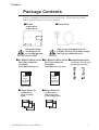


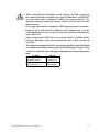


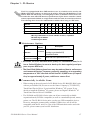


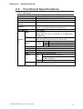


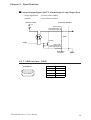
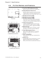
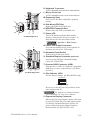
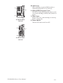
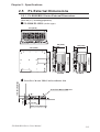

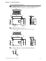

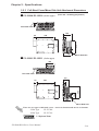


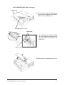


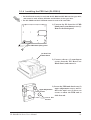
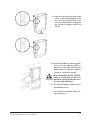


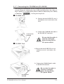


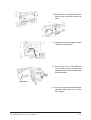


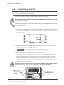


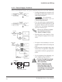
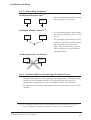


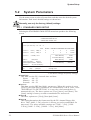

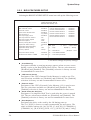
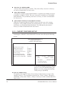
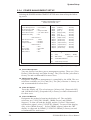


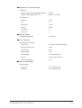


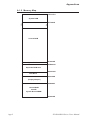
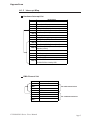


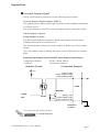
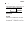
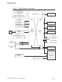

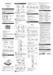

![Installation Manual [PDF 2.5 MB]](http://vs1.manualzilla.com/store/data/006019755_1-cd5e1ac77f4b7b55781d3fd4e75d7494-150x150.png)
![Installation Manual [PDF 3.2 MB]](http://vs1.manualzilla.com/store/data/006030502_1-1df8339044a93376c13535e606991dae-150x150.png)