1
User’s
Manual
Models SR10001/SR10002/SR10003/SR10004/
SR10006
SR10000 Recorder
Yokogawa Electric Corporation
IM 04P03B01-01E
2nd Edition
Foreword
Thank you for purchasing the YOKOGAWA SR10000 Recorder.
This user’s manual explains how to use the SR10000 recorder excluding the
communication functions. To ensure correct use, please read this manual thoroughly
before operation.
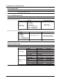
The following three manuals including this manual are available for the SR10000
Recorder.
• Paper Manual
Manual Title
Manual No.
Description
SR10000 Recorder
Operation Guide
IM 04P03B01-02E
Explains concisely the operations of the
SR10000 Recorder. It is also provided in the
CD-ROM.
• Electronic Manuals Provided on the Accompanying CD-ROM
Manual Title
Manual No.
Description
SR10000 Recorder
Operation Guide
IM 04P03B01-02E
Explains concisely the operations of the
SR10000 Recorder. This is the electronic
version of the paper manual.
SR10000 Recorder
User’s Manual
IM 04P03B01-01E
This manual.
SR10000
IM 04P03B01-17E
Communication Interface
User’s Manual
Explains the communication functions of the
SR10000 Recorder using Ethernet interface and
the RS-422A/485 communication interface.
Notes
• The contents of this manual are subject to change without prior notice as a result of
continuing improvements to the instrument’s performance and functions.
• Every effort has been made in the preparation of this manual to ensure the accuracy
of its contents. However, should you have any questions or find any errors, please
contact your nearest YOKOGAWA dealer as listed on the back cover of this manual.
• Copying or reproducing all or any part of the contents of this manual without the
permission of Yokogawa Electric Corporation is strictly prohibited.
• The TCP/IP software of this product and the document concerning the TCP/IP
software have been developed/created by YOKOGAWA based on the BSD
Networking Software, Release 1 that has been licensed from the University of
California.
Trademarks
• All the brands or names of Yokogawa Electric’s products used in this manual are
either trademarks or registered trademarks of Yokogawa Electric Corporation.
• Microsoft, MS-DOS, Windows, Windows NT, and Windows XP are either registered
trademarks or trademarks of Microsoft Corporation in the United States and/or other
countries.
• Adobe, Acrobat, and PostScript are trademarks of Adobe Systems incorporated.
• For purposes of this manual, the TM and ® symbols do not accompany their
respective trademark names or registered trademark names.
• Company and product names that appear in this manual are trademarks or registered
trademarks of their respective holders.
Revisions
1st Edition
2nd Edition
February 2006
October 2006
2nd Edition: October 2006 (YK)
All Rights Reserved, Copyright © 2006 Yokogawa Electric Corporation
IM 04P03B01-01E
i
How to Use This Manual
Structure of the Manual
Read the Operation Guide first to familiarize yourself with the basic operation, and
then read this manual. For a description of the communication function, see the
SR10000 Communication Interface User's Manual (IM 04P03B01-17E).
This user's manual consists of the following sections.
Chapter
Title and Description
1
Functional Explanation and Setup Guide
Describes the functions of the SR10000 Recorder and provides a function setup
guide. Refer to this chapter when you are unsure of the details of the function that
you are operating.
2
Frequently Used Setup Operations (Setting Mode)
Describes how to change the input range, alarms, chart speed, etc.
3
Setup Operations for Convenient Functions (Setting Mode)
Describes the setup operations for convenient functions such as how to assign tags
to channels and how to set message strings that are to be printed.
4
Setup Operations for Changing/Adding Functions (Basic Setting Mode)
Describes the setup operations for changing or adding functions such as setting the
recorder to detect sensor burnouts and changing the contents that are printed on the
chart paper.
5
Troubleshooting
Describes error message and troubleshooting measures of the SR10000 Recorder.
6
Maintenance
Describes periodic inspection, calibration, and pen adjustment/printer carriage
adjustment.
7
Specifications
Gives the specifications of the SR10000 Recorder.
Appendix Describes the printout contents.
Index
Note
•
This user’s manual covers information regarding the recorders with English as the printout
font (suffix code “2”).
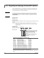
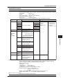
Recorder’s Version and Functions Described in This Manual
The contents of this manual corresponds to the recorder with version 1.31.
SR10000 Versions and Functions
Version
Suffix Code
1.21 or earlier –
1.31
/BT1
Added or Modified Functions
–
(Added)
Header printout
• Checking the Version Number
Press the FUNC key,
key, or
key to select VER (
Hold down the FUNC key to return to Operation mode.
Reference
–
Section 1.3
), then press the
key.
Software (Sold Separately)
The table below shows the relationship between the RXA10 Configuration Software
revisions and the SR10000 recorder versions.
Recorder version
RXA10 Configuration R3.01
Software revision
Yes:
ii
1.21 or earlier
Yes
1.31
Yes
Compatible
IM 04P03B01-01E
How to Use This Manual
1
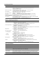
Conventions Used in This Manual
Unit
K ........ Denotes 1024. Example: 768 KB (file size)
k ........ Denotes 1000.
2
Safety Markings
The following markings are used in this manual.
3
Improper handling or use can lead to injury to the user or
damage to the instrument. This symbol appears on the
instrument to indicate that the user must refer to the user’s
manual for special instructions. The same symbol appears in
the corresponding place in the user’s manual to identify those
instructions. In the manual, the symbol is used in conjunction
with the word “WARNING” or “CAUTION.”
WARNING
4
5
Calls attention to actions or conditions that could cause serious
or fatal injury to the user, and precautions that can be taken to
6
prevent such occurrences.
CAUTION
Calls attentions to actions or conditions that could cause light
injury to the user or damage to the instrument or user’s data,
and precautions that can be taken to prevent such occurrences.
Note
Calls attention to information that is important for proper
App
operation of the instrument.
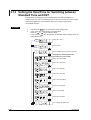
Subheadings
On pages that describe the operating procedures in Chapter 2 through 4 and 6, the
following symbols are used to distinguish the procedures from their explanations.
Procedure
Index
Follow the numbered steps. All procedures are written with
inexperienced users in mind; depending on the operation, not
all steps need to be taken.
Explanation
This subsection describes the setting parameters and the
limitations on the procedures. It does not give a detailed
explanation of the function. For details on the function, see
chapter 1.
IM 04P03B01-01E
7
iii
Contents
Foreword ......................................................................................................................................... i
How to Use This Manual ................................................................................................................. ii
Chapter 1 Functional Explanation and Setup Guide
1.1
1.2
1.3
1.4
1.5
1.6
Measuring Input Section .................................................................................................. 1-1
Alarms .............................................................................................................................. 1-6
Recording ......................................................................................................................... 1-8
Remote Control Function (/R1 Option) .......................................................................... 1-19
Other Functions ............................................................................................................. 1-21
Function Setup Guide .................................................................................................... 1-23
Chapter 2 Frequently Used Setup Operations (Setting Mode)
2.1
2.2
2.3
2.4
2.5
Setting the Input Range ................................................................................................... 2-1
Setting the Alarm .............................................................................................................. 2-9
Setting the Unit on Linearly Scaled Channels ................................................................ 2-11
Changing the Chart Speed ............................................................................................ 2-12
Setting the Date/Time .................................................................................................... 2-13
Chapter 3 Setup Operations for Convenient Functions (Setting Mode)
3.1
3.2
3.3
3.4
3.5
3.6
3.7
3.8
3.9
3.10
3.11
3.12
3.13
3.14
Setting the Trend Recording Interval (Dot Model) ............................................................ 3-1
Setting the Filter (Pen Model) .......................................................................................... 3-2
Setting the Moving Average (Dot Model) ......................................................................... 3-3
Setting Recording Zones for Each Channel (Zone Recording) ........................................ 3-4
Setting the Partial Expanded Recording .......................................................................... 3-5
Turning Trend Recording (Dot Model) and Periodic Printout ON/OFF for Each Channel 3-6
Setting Tags on Channels ................................................................................................ 3-7
Setting the Message String .............................................................................................. 3-8
Setting the Secondary Chart Speed (Remote Control Function, /R1) ............................. 3-9
Applying a Bias on the Measuring Input Signal ............................................................. 3-10
Performing Calibration Correction (/CC1 Option) .......................................................... 3-11
Setting Up Start Printout and End printout (/BT1 Option) .............................................. 3-13
Regarding the Message Format (/BT1 Option) .............................................................. 3-18
Setting the Date/Time for Switching between Standard Time and DST ......................... 3-20
Chapter 4 Setup Operations for Changing/Adding Functions
(Basic Setting Mode)
4.1
4.2
4.3
4.4
4.5
4.6
4.7
4.8
4.9
4.10
4.11
iv
Changing the Auxiliary Alarm Function ............................................................................ 4-1
Changing the Integration Time of the A/D Converter ....................................................... 4-3
Setting the Burnout Detection Function ........................................................................... 4-4
Setting the RJC Function on TC Input Channels ............................................................. 4-5
Changing the Channel Recording Color (Dot Model) ...................................................... 4-6
Recording by Compensating for the Pen Offset along the Time Axis (Pen Model) .......... 4-7
Turning Printouts ON/OFF (Selecting the Channel/Tag Printout and Turning ON/OFF the
Channel, Alarm, Recording Start, New Chart Speed, Scale, and Pen Color
Printouts) .............................................................................................................. 4-8
Turning Periodic Printout ON and OFF and Setting the Interval .................................... 4-10
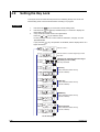
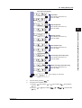
Setting the Key Lock ...................................................................................................... 4-12
Enabling the Moving Average Function (Dot Model) ...................................................... 4-15
Enabling the Filter Function (Pen Model) ....................................................................... 4-16
IM 04P03B01-01E
Contents
4.12
4.13
4.14
4.15
4.16
4.17
4.18
4.19
4.20
4.21
4.22
4.23
4.24
Enabling the Partial Expanded Recording Function ...................................................... 4-17
Changing the Printout Font ............................................................................................ 4-18
Changing the Print/Display Format of the Date ............................................................. 4-19
Enabling the Bias, Low-Cut, and Calibration Correction (/CC1 Option) Functions ........ 4-20
Changing the Time Printout Format ............................................................................... 4-22
Initializing the Settings ................................................................................................... 4-24
Assigning Functions to the Remote Control Input Terminals (/R1 Option) ..................... 4-25
Selecting to Show/Hide the FUNC Key Menus .............................................................. 4-27
Selecting to Show/Hide Setting Mode Menus ................................................................ 4-29
Enabling/Disabling the Customized Menu ..................................................................... 4-31
Setting the Calibration Correction Function (/CC1 Option) ............................................ 4-34
Enabling Start Printout, End printout, and Message Format (/BT1 Option) ................... 4-35
Changing the Temperature Unit ..................................................................................... 4-37
Chapter 5 Troubleshooting
5.1
5.2
A List of Error Messages .................................................................................................. 5-1
Troubleshooting Flow Charts ........................................................................................... 5-4
Chapter 6 Maintenance
6.1
6.2
6.3
6.4
6.5
Periodic Inspection ........................................................................................................... 6-1
Cleaning the Recorder ..................................................................................................... 6-2
Calibrating the Recorder .................................................................................................. 6-3
Adjusting the Pen Position (Pen Model) .......................................................................... 6-5
Adjusting the Dot Printing Position (Dot Model) ............................................................... 6-7
1
2
3
4
5
6
7
Chapter 7 Specifications
7.1
7.2
7.3
7.4
7.5
7.6
Input Specifications .......................................................................................................... 7-1
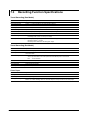
Alarm Function Specifications .......................................................................................... 7-3
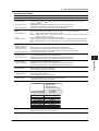
Recording Function Specifications ................................................................................... 7-4
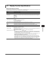
Display Function Specifications ....................................................................................... 7-7
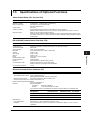
Specifications of Optional Functions ................................................................................ 7-9
General Specifications ................................................................................................... 7-13
Appendix
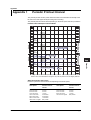
Appendix 1
Periodic Printout Interval ................................................................................ App-1
Index
IM 04P03B01-01E
v
App
Index
Chapter 1 Functional Explanation and Setup Guide
1.1
1
Measuring Input Section
Functional Explanation and Setup Guide
Input Section
Number of Measurement Channels and Scan Interval
The recorder samples the input signals on the measurement channels at the scan
interval to obtain the measured values.
Model
Number of Channels
Scan Interval
1-pen model
2-pen model
3-pen model
4-pen model
Dot model
1
2
3
4
6
125 ms
125 ms
125 ms
125 ms
1s
(However, the scan interval is 2.5 s when the
integration time of the A/D converter is 100 ms.)
Input Type, Measurable Range, and Computation
The recorder can measure the following types of inputs.
Input Type
Measurable Range
DC voltage
DC voltage in the range of ±20 mV to ± 50 V
1-5V
See “1-5V” below.
Thermocouple Temperature range corresponding to each type: R, S, B, K, E, J, T, N, W, L, U,
and WRe
RTD
Temperature range corresponding to each type: Pt100Ω and JPt100Ω
ON/OFF input Contact input: Open contact is OFF (0). Closed contact is ON (1).
Voltage input: Less than 2.4 V is OFF (0). Greater than or equal to 2.4 V is ON (1).
Within ±6 V.
• 1-5V
1-5V is scaled to values in the appropriate unit to be used as measured values. Also,
the low-cut function (input less than 0% is fixed to 0% (scale left value)) can be used.
• Current Input
A shunt resistor is attached to the input terminal. The current signal is converted to a
voltage signal and measured. The measurable range is the range equivalent to the
“DC voltage” range indicated above after converting the current to the voltage signal.
Note
Three types of shunt resistors (250 Ω, 100 Ω, and 10 Ω) are available for current input (See
“Optional Accessories (Sold Separately)” in the Operation Guide). For example, a 250-Ω
shunt resistor is used to convert the signal to the range of 1 to 5 V for 4 to 20 mA input.
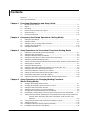
• Range Type, Measurable Range, and Recording Span
Various “range type” are available for the different types of inputs (for example
thermocouple type R). Each range type has a preset measurable range (0.0 to
1760.0°C for thermocouple type R). Measurement can be made by specifying an
arbitrary range within the measurable range as the input range. The measured values
in the input range are recorded on the chart paper. The range of measured values
that are recorded is called the recording span.
Measurable range (Thermocouple Type R example)
1760.0°C
Input range or recording span
1500.0°C (rightmost value of span)
300.0°C (leftmost value of span)
0.0°C
<Related Topics> Setting the input range: Section 5.1
For the procedure to set the functions, see section 1.6, “Function Setup Guide.”
IM 04P03B01-01E
1-1
1.1 Measuring Input Section
• Delta Computation
The value obtained by subtracting the measured value of another channel (called the
reference channel) from the input value of the channel set to delta computation is used
as the measured value of that channel. The reference channel must be assigned to a
channel whose channel number is less than that of the channel on which delta
computation is specified. The channel on which delta computation is specified is
automatically set to the same range type as the reference channel.
Channel set to delta computation
Input
value
Measured value
–
Measured value on the reference channel
Note
A channel whose input type is set to DC voltage, TC, or RTD can be designated as a
reference channel. However, channels set to scaling or square root computation cannot be
designated.
• Scaling
The input values are scaled to values in the appropriate unit to be used as measured
values.
Input value
10 V
Measured value
300.0°C
0V
−100.0°C
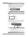
• Square Root Computation
When the input type is DC voltage, the square root of the input value is calculated, the
result is scaled to a value in the appropriate unit, and used as the measured value of
the channel. Also, the low-cut function (input less than a given measured value is
fixed to 0% (scale left value)) can be used.
Channel set to square root computation
Input value
√
Scaling
Measured value
Measured value
Result of square
root computation
Low-cut value
Input value
Note
The square root computation on the recorder uses the following formula.
Fx = ( Fmax - Fmin )
Vx - Vmin
Vmax - Vmin
+ Fmin
where Vmin (leftmost value of span) < Vmax (rightmost value of span)
Fmin (leftmost value of scale after scaling) < Fmax (rightmost value of scale after
scaling)
Vx is the input voltage and Fx is the scaled value
<Related Topics> Setting the input range: Section 5.1
For the procedure to set the functions, see section 1.6, “Function Setup Guide.”
1-2
IM 04P03B01-01E
1.1 Measuring Input Section
1
Biased channel
Input value
Measured value
+
Bias value
<Related Topics> Setting the bias: Sections 4.15 and 3.10
• Calibration Correction (/CC1 Option)
Corrects the measured value of each channel using segment linearizer approximation
and makes the resultant value the measured value of the channel. You can set
arbitrary correction values for 2 to 16 points of arbitrary measured values. Linear
approximation is used between two segment points. Correction values can be
assigned using revise values or absolute values.
Scale value
B5
Measured value
A5
A4
Correction
value
B3
B4
B2
A3
B1
A2
A1
Correction using
revise values
Measured value = A
Correction value = B – A
Correction using
absolute values
Measured value = A
Correction value = B
A1 to A5: Measured value (measured value before correction)
B1 to B5: Correction value (measured value after correction)
Calibration point
<Related Topics> Setting the calibration correction function: Sections 4.15, 4.22, and
3.11
Burnout Detection of Thermocouples
This function makes the recording go off the scale to the right or left when the
thermocouple burns out while measuring temperature with a thermocouple. This function
can also be used on 1-5V. The burnout detection function can be set for each channel.
By default, this function is disabled.
Note
For 1-5V, a burnout occurs when the input value is less than or equal to 0.2 V.
<Related Topics> Setting the burnout detection function: Section 4.3
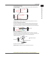
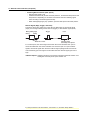
Reference Junction Compensation of Thermocouple Input
When measuring the temperature using a thermocouple, the reference junction
compensation on the recorder can be used. When using external reference junction
compensation, you can set the reference voltage. The reference junction compensation
can be set for each channel.
By default, the recorder is configured to use the internal reference junction compensation
function.
For the procedure to set the functions, see section 1.6, “Function Setup Guide.”
IM 04P03B01-01E
1-3
Functional Explanation and Setup Guide
• Bias
A given value (bias value) is added to the input value and used as the measured
value of that channel.
1.1 Measuring Input Section
Note
When using external reference junction compensation, set an appropriate reference junction
compensation voltage. For example, if the reference junction temperature of the external
reference compensation is T0 °C, set the reference compensation junction voltage to the
thermoelectromotive force of the 0°C reference of T0 °C.
Example when using external reference junction compensation
External reference junction compensation
Recorder
(Hold the contact point of the thermocouple
and copper wire at T0°C)
Copper wire
Thermocouple
<Related Topics> Setting the reference junction compensation function: Section 4.4
Noise Elimination from Input Signals
Filter and Moving Average
This function used to suppress the effects of noise that is riding on the signal. The pen
model and dot model are equipped with a filter function and a moving average function,
respectively. The function can be set for each measurement channel. However, it does
not operate on channels set to ON/OFF input.
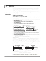
• Filter (Pen Model)
The filter is a low-pass filter. The time constant can be set to 2 s, 5 s, or 10 s.
Filter result (output for a step input)
Input signal
63.2% of the output value
Output response curve
(when using the filter)
2, 5, 10 s (time constant, the time it takes
to reach 63.2% of the output value)
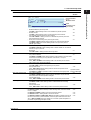
• Moving Average (Dot Model)
The average value of the m most recent values acquired at the scan interval is used
as the measured value of the channel. The number of moving-averaged data points
(m) can be set in the range 2 to 16. The figure below shows an example indicating the
operation of the buffer for the moving average computation when the number of
moving averaged data points is set to 5.
Buffer data for the
nth sampling time
Buffer data for the
n+1th sampling time
Buffer data for the
n+2th sampling time
Most recent data
Most recent data
1
10.0 mV
15.0 mV
10.0 mV
2
5.0 mV
10.0 mV
15.0 mV
3
0.0 mV
5.0 mV
10.0 mV
4
–5.0 mV
0.0 mV
5.0 mV
5
–10.0 mV
–5.0 mV
Deleted
Moving
average
0.0 mV
0.0 mV
Deleted
5.0 mV
8.0 mV
<Related Topics> Setting the filter: Sections 4.11 and 3.2
Setting the moving average: Sections 4.10 and 3.3
For the procedure to set the functions, see section 1.6, “Function Setup Guide.”
1-4
IM 04P03B01-01E
1.1 Measuring Input Section
1
Integration Time of the A/D Converter
Model
Integration Time of the A/D Converter
Pen model
Select 16.7 ms (60 Hz), 20 ms (50 Hz), or Auto
Dot model
Select 16.7 ms (60 Hz), 20 ms (50 Hz), 100 ms or Auto
• If Auto is selected, the recorder detects the power supply frequency and automatically
selects 16.7 ms or 20 ms.
• If Auto is specified when using the 24-VDC power supply on a recorder with the 24VDC/AC power supply (/P1 option), the integration time is fixed to 20 ms (50 Hz).
• Because 100 ms is an integer multiple of 16.7 ms and 20 ms, this setting can be used
to suppress the power frequency noise for either frequency, 50 Hz or 60 Hz.
• The scan interval on the dot model is 1 s when the integration time is set to 16.7 ms or
20 ms and 2.5 s when the integration time is set to 100 ms.
<Related Topics> Setting the A/D integration time: Section 4.2
For the procedure to set the functions, see section 1.6, “Function Setup Guide.”
IM 04P03B01-01E
1-5
Functional Explanation and Setup Guide
The recorder uses an A/D converter to convert the sampled analog signal to a digital
signal. By setting the integration time of the A/D converter to match the time period
corresponding to one cycle of the power supply or an integer multiple of one cycle, the
power supply frequency noise can be effectively suppressed.
The integration time of the A/D converter is selected according to the model from the
table below.
1.2
Alarms
This function generates an alarm when the measured data meets a certain condition.
The alarm status is displayed on the screen while recording the alarm occurrence/
release on the chart paper.
Also, alarm output relays can be used to output contact signals when alarms occur (/A1,
/A2, and /A3 options).
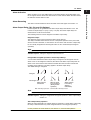
Alarm Types
Number of Alarm Point Marks
Up to four alarms can be set for each channel.
Alarm Conditions
The following four conditions are available: The alphanumeric character or symbol inside
the parentheses is used on the recorder to denote each alarm.
• High Limit Alarm (H/ )
An alarm occurs when the input value exceeds the alarm value.
• Low Limit Alarm (L/ )
An alarm occurs when the input value falls below the alarm value.
Low limit alarm
High limit alarm
Alarm
value
Alarm occurrence
Alarm release
Measured value
Measured Alarm release
value
Alarm occurrence
Alarm value
• Difference High Limit Alarm (h/ )*
An alarm occurs when the difference in the input values of two channels is greater
than or equal to the specified value.
• Difference Low Limit Alarm (l/ )*
An alarm occurs when the difference in the input values of two channels is less than
or equal to the specified value.
*
Can be specified on channels set to delta computation.
Alarm Hysteresis
Hysteresis can be specified to the values for activating and releasing the alarm. The
hysteresis applies only to high limit alarm (H) and low limit alarm (L). The hysteresis
width can be set in the range of 0.0% (OFF) to 1.0% of the recording span in 0.1 steps.
The setting applies to all high limit alarms and low limit alarms. By default, the hysteresis
width is set to 0.5%.
Low limit alarm
High limit alarm
Alarm occurrence
Alarm
value
Measured
value
Alarm release
Hysteresis
(1% or less)
Measured value
Alarm release
Alarm value
Alarm occurrence
<Related Topics> Setting alarms: Section 2.2
Setting the alarm hysteresis: Section 4.1
For the procedure to set the functions, see section 1.6, “Function Setup Guide.”
1-6
IM 04P03B01-01E
1.2 Alarms
1
Alarm Indication
Alarm Recording
The alarm occurrence/release can be recorded on the chart paper. See section 1.3.
Alarm Output Relay (/A1, /A2, and /A3 Options)
Contact signals can be generated from alarm output relays when alarms occur. The
number of output relays is 2 (/A1), 4 (/A2), or 6 (/A3). The alarm output relays are
denoted as I01 to I06 on the recorder.
The following functions can be assigned to the alarm output relay.
Diagnosis Output
The diagnosis output can be assigned to alarm output relay I01.
The relay is activated when there is an error in the plotter operation on the pen model,
when a burnout is detected, or when there is an error in the A/D converter. Output relay
I01 is normally energized and de-energizes when an error is detected (de-energized
operation).
Note
If diagnosis output is enabled, I01 becomes a relay dedicated to diagnosis output.
<Related Topics> Setting the diagnosis output: Section 4.1
Energized/De-energized Operation of Alarm Output Relays
You can select whether the alarm output relay is energized or de-energized when an
alarm occurs. If de-energized is selected, the status of the alarm output relay when an
alarm occurs is the same as the status that results when the recorder is turned OFF
(including power failures). The setting applies to all alarm output relays.
The default setting is energized.
Energize
NO
C
NC
De-energize NO
C
NC
When power is
turned OFF
NO
C
NC
NO
C
NC
When an alarm
is not occurring
(During normal
operation)
NO
NO
C
NC
C
NC
When an alarm
is occurring
(During a
malfunction)
NO : Normally Opened, C : Common, NC : Normally Closed
Note
If diagnosis output is enabled, I01 is fixed to de-energized operation.
<Related Topics> Setting the energized/de-energized operation of alarm output relays:
Section 4.1
Alarm Output Relay Operation
When the output destination of multiple alarms is assigned to a single alarm output relay,
the relay is activated when any of the assigned alarms is occurring (OR operation).
For the procedure to set the functions, see section 1.6, “Function Setup Guide.”
IM 04P03B01-01E
1-7
Functional Explanation and Setup Guide
When an alarm occurs, the ALM indicator in the status display section illuminates, and
the 2nd digit of the LED shows the alarm status for each channel. When the alarm clears,
the indicator and the LED turn OFF.
1.3
Recording
The recorder is capable of recording the measured values with pens or dots (trend
recording) as well as various other types of information.
Trend Recording
The measured values are printed within a width of 100 mm.
Recording Method (Pen Model)
• The measured value is updated every scan interval and continuously recorded.
• The recording colors in order from channel 1 are red, green, blue, and violet.
Recording Method (Dot Model)
• The most recent measured value is recorded with a dot every dot printing interval.
The dot printing interval is in the range of 10 s to 90 s. There are two recording
methods from which you can select. One method automatically adjusts the dot
printing interval according to the chart speed so that the dots do not overlap. The
other method records at the fastest dot printing interval at all times.
• The recording colors in order from channel 1 are purple, red, green, blue, brown, and
black. The recording color of each channel can be changed among these six colors.
• For each channel, trend recording can be enabled or disabled.
<Related Topics> Setting the trend recording interval: Section 3.1
Changing the recording color: Section 4.5
Enabling/Disabling trend recording for each channel: Section 3.6
Chart Speed
On the pen model, the chart speed can be selected from 40 settings in the range of 10 to
12000 mm/h.
On the dot model, the chart speed can be selected from 28 settings in the range of 10 to
1500 mm/h.
The default setting is 20 mm/h.
<Related Topics> Setting the chart speed: Section 2.4
Zone Recording
A recording zone is assigned to each channel. This function is useful such when the
recording results overlap making them difficult to be viewed.
Zone 1
Zone 2
Zone 3
Zone 4
<Related Topics> Setting the zone recording: Section 3.4
For the procedure to set the functions, see section 1.6, “Function Setup Guide.”
1-8
IM 04P03B01-01E
1.3 Recording
1
Compressed
Functional Explanation and Setup Guide
Partial Expanded Recording
This function expands a section of the recording range. By default, partial expanded
recording is disabled.
Expanded
<Related Topics> Setting the partial expanded recording: Sections 4.12 and 3.5
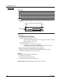
Pen Offset Compensation (Pen Model)
This function compensates for the pen offset (phase difference) along the time axis.
On 2-pen, 3-pen, and 4-pen recorders, there are offsets along the time axis (phase
difference) between the pens. This offset is corrected when pen offset compensation is
used.
Same time
Below is an explanation for the 2-pen model.
The recording of these two pens are offset by an amount of phase P. If pen offset
compensation is enabled, the measured values of pen 1 are stored in the memory, and
recorded when the chart paper is fed by an amount corresponding to P.
Reference pen (pen 2)
Pen 1
Recorder front panel
Chart paper
P
Chart feeding direction
By default, this function is disabled.
<Related Topics> Setting the pen offset compensation: Section 4.6
For the procedure to set the functions, see section 1.6, “Function Setup Guide.”
IM 04P03B01-01E
1-9
1.3 Recording
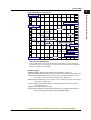
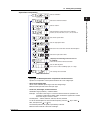
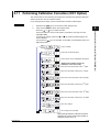
Printout
The figure below is used to explain the printout contents. The actual printout and font are
different from those illustrated in the figure. The printout positions are also slightly
different.
Printout Example on the Pen Model
Manual printout
Jan.31.05 15:00
1
223.5mg/cm3
3 H 591.6˚C
2
4d
437.2µS/cm
−0.222V
New chart speed printout
50mm/h 14:55
Periodic printout
Time tick cancel mark
Jan.31.05!
13:50*
Pen offset compensation mark
1
218.7mg/cm3
2
390.6µS/cm
3
H 598.4˚C
4
d −0.222V
0.0
1CH
Alarm
RED
Delta computation
50mm/h_
Time tick
Recording color
Scale
500.0
mg/cm3
Buffer overflow mark
Alarm printout
1H3*10:09
1H3 10:05
Message printout
09:52*START#205 ABCDEF
Recording start printout
08:00 25mm/h
Time tick
The time ticks are marks that indicate the positions of the date/time on the chart paper.
Time tick cancel mark
An exclamation point (!) is printed when the periodic printout time tick was not printed at the
correct position.
Channel number or tag printout
Channel numbers or tags can be printed.
<Related Topics>
Switching between channel number printout and tag printout: Section 4.7
Setting the periodic printout (interval, reference time, and periodic printout ON/OFF): Section 4.8
Turning printout ON/OFF (alarm printout, recording start printout, new chart speed printout, scale
printout for periodic printout, and recording color printout for periodic printout) : Section 4.7
Setting the time format (alarm printout, message printout, recording start printout, and new chart
speed printout): Section 4.16
Turning periodic printout ON/OFF for each channel: Section 3.6
Setting the message string: Section 3.8
Executing manual printouts, executing message printouts, clearing the alarm printout
buffer, and printing out settings: see the Operation Guide)
For the procedure to set the functions, see section 1.6, “Function Setup Guide.”
1-10
IM 04P03B01-01E
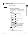
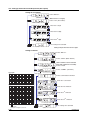
1.3 Recording
1
Printout Example on the Dot Model
Jan.31.05 16:00
1
223.5mg/cm3
3 H 591.6˚C
5
−0.665V
Functional Explanation and Setup Guide
Manual printout
2
437.2µS/cm
4d −0.222V
6 L −0.448V
New chart speed printout
_50mm/h 14:55
Periodic printout
Jan.31.05
13:50
Time tick
1
218.7mg/cm3
2
390.6µS/cm
3
H 598.4˚C
4
d −0.222V
5
−0.995V
6
L −0.448V
0.0
1CH
Delta computation
50mm/h_
Alarm
Scale
500.0
mg/cm3
Buffer overflow mark
Time tick
Alarm printout
1H3*10:09
1H3 10:05
Message printout
09:52*START#205 ABCDEF
Recording start printout
Channel printout
Time tick
_08:00 25mm/h
Channel Printout (Dot Model Only)
Prints the channel No. or tag by the trend recording. The channel No. or tag is printed every
approximately 25 mm on the chart paper. The channel printout can be enabled or disabled. By
default, the channel printout is enabled.
<Related Topics>
Switching between channel number printout and tag printout: Section 4.7
Setting the periodic printout (interval, reference time, and periodic printout ON/OFF): Section 4.8
Turning printout ON/OFF (channel printout, alarm printout, recording start printout, new chart
speed printout, and scale printout for periodic printout): Section 4.7
Setting the time format (alarm printout, message printout, recording start printout, and new chart
speed printout): Section 4.16
Turning recording and printout ON/OFF for each channel (trend recording and periodic
printout): Section 3.6
Setting the message string: Sections 3.8
Executing manual printouts, executing message printouts, clearing the alarm printout
buffer, and printing out settings: see the Operation Guide)
For the procedure to set the functions, see section 1.6, “Function Setup Guide.”
IM 04P03B01-01E
1-11
1.3 Recording
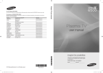
Periodic Printout
Values such as the measured values are printed at a determined interval. The contents
of the printout vary between the pen model and dot model.
Printout cannot be performed at the following chart speeds.
Pen model: 1800 mm/h or higher; Dot model: 120 mm/h or higher
Channel No.
or tag
Date
Time
Channel data
Scale
Recording color
Chart speed
Measured
value
Unit
Time tick cancel mark
Offset compensation mark
Mar.31.2006!
15:50*
TAG-001
1.000V
2
-1.000V
3
H-2.1050UNIT03
4
d
2.000V
0.000
TAG-001
RED
50mm/h_
Time tick
Prints the letter “d” for channels set to
delta computation.
2.000
V
Alarm
The font used in the figure differs from that of the actual printout. The printout positions may
also differ from those of the actual printout.
• Printout Contents
• Date/Time:
The date/time when the periodic printout was executed.
• Time ticks:
Marks that indicate the first pen position of the date/time on the
chart paper. If the time tick is not printed in the correct position, the
pen model prints a time tick cancel mark (!), and the dot model does
not print the time tick.
• Offset compensation mark: When pen offset is being executed on the pen model,
asterisks (∗) are printed.
• Channel data: Prints the channel numbers or tags, measured values
(instantaneous values), and units.
• Alarm status: Prints the alarm that is occurring. Prints the letter “d” on channels
set to delta computation. If multiple alarms are occurring, the alarm
with the highest precedence is printed.
Alarm printout precedence: (Higher) H, L, h, and l (lower)
• Scale:
Prints the leftmost and rightmost values of the recording span and
the channel number or tag for channels that have scale printout
specified. The scale is printed for one channel at each periodic
printout. The channel whose scale is printed changes in ascending
order. The scale of channels that are being zone recorded is printed
within the recording range of the zone for 40 mm or greater.
• Recording color (pen model): Prints the recording colors of channels that have
scale printout and recording color printout specified.
• Chart speed: The chart speed can be printed.
• For the measured values and alarm status, you can select whether to print them for
each channel. For the scale and recording color (pen model), you can select
whether to print them.
• Interval (for details, see appendix 1)
The printout interval can be set by specifying the value or set automatically in sync
with the chart speed.
• Turning ON/OFF the Periodic Printout
Periodic printout can be turn ON/OFF. By default, periodic printout is enabled with the
interval synchronized to the chart speed.
For the procedure to set the functions, see section 1.6, “Function Setup Guide.”
1-12
IM 04P03B01-01E
1.3 Recording
1
Time of alarm occurrence/release
Indicates that there are alarms that are not
printed because the alarm printout buffer is full.
Level number
Alarm type (H: high limit, L: low limit, h: difference high limit,
and l: difference low limit)
Channel No. or tag
: Alarm occurrence,
: Alarm release
• The print condition can be set to (1) print when alarms occur and release, (2) print
only when alarms occur, or (3) do not print.
• Alarms that occur while an alarm printout is in progress are temporarily saved to the
buffer memory in a printout-wait condition. Alarms are cleared from the buffer memory
when they are printed.
• The number alarms that can be stored in the buffer is 8 and 12 on the pen model and
dot model, respectively. Alarms that occur while the buffer is full are not printed. A
buffer overflow mark is printed when there are alarms that cannot be printed because
the buffer is full.
• The time printout format can be selected.
Manual Printout
Measured values and alarm status can be printed manually using the keys. When
manual printout is executed, trend recording stops and restarts when manual printout is
complete.
<For the operation procedure, see the Operation Guide.>
Message Printout
Printout cannot be performed at the following chart speeds.
Pen model: 1800 mm/h or higher; Dot model: 120 mm/h or higher
Preset messages can be printed on the chart paper using the keys. Five messages,
each within 16 characters, can be registered in advance.
• If message printout is executed while another message is being printed, the most
recent message is temporarily stored to the buffer memory in a printout-wait condition.
Messages are cleared from the buffer memory when they are printed.
• The number of messages that can be stored in the buffer is 5. If message printout is
executed when the buffer is full, the message is not printed. A buffer overflow mark is
printed when there are messages that cannot be printed because the buffer is full.
• The time printout format can be selected.
New Chart Speed Printout
Printout cannot be performed at the following chart speeds.
Pen model: 1800 mm/h or higher; Dot model: 120 mm/h or higher
• When the chart speed is changed, the time tick (dot model), the date/time of change,
and the new chart speed are printed. An asterisk (∗) shows there are messages that
cannot be printed.
• The time printout format can be selected.
For the procedure to set the functions, see section 1.6, “Function Setup Guide.”
IM 04P03B01-01E
1-13
Functional Explanation and Setup Guide
Alarm Printout
Alarm information is printed when an alarm occurs or releases.
Printout cannot be performed at the following chart speeds.
Pen model: 1800 mm/h or higher; Dot model: 120 mm/h or higher
1.3 Recording
Recording Start Printout
Printout cannot be performed at the following chart speeds.
Pen model: 1800 mm/h or higher; Dot model: 120 mm/h or higher
When recording is started, the time tick (dot model), the time, and the chart speed can
be printed. An asterisk (∗) shows there are messages that cannot be printed.
• The recording start printout can be enabled or disabled. By default, the recording start
printout is disabled.
• The time printout format can be selected.
Printout/Display Format of the Date.
The printout/display format of the date can be selected from the list below.
Selectable
Settings
Type
Printout Format
Example
Display Format
Example
Notes
Year/Month/Day
Month/Day/Year
Day/Month/Year
Day.Month.Year
Month.Day.Year
2006/03/31
03/31/2006
31/03/2006
31.03.2006
Mar.31.2006
06
03
31
31
03
Default value
03
31
03
03
31
31
06
06
06
06
*1 These do not apply for the date printout format for message printouts that include measured
values (/BT1 option). Specify that in the message format.
Printout Format of the Time
The printout format of the time can be selected from the list below.
Selectable
Settings
Type
Printout Format
Example
Notes
Hour:Minute
Hour:Minute:Second
Month/Day Hour:Minute
Month/Day Hour:Minute:Second
Year/Month/Day Hour:Minute:Second
10:00
Default value
10:00:00
03/31 10:00
03/31 10:00:00
2006/03/31 10:00:00
*1: The year/month/day format varies depending on the printout/display format of the date.
*2: Can be set to the alarm printout, message printout, recording start printout, and new chart
speed printout.
*3 These do not apply for the date printout format for message printouts that include measured
values (/BT1 option). Specify that in the message format.
<Related Topics> Setting the printout/display format of the date: Section 4.14
Setting the printout format of the time: Section 4.16
For the procedure to set the functions, see section 1.6, “Function Setup Guide.”
1-14
IM 04P03B01-01E
1.3 Recording
The printout examples may appear differently from the actual printout as a result of functional
improvements made on the recorder after this manual was written.
For the procedure to set the functions, see section 1.6, “Function Setup Guide.”
IM 04P03B01-01E
1-15
1
Functional Explanation and Setup Guide
Setting Printout
List or setup list can be printed. When setting printout is executed, trend recording stops
and restarts when the printout is complete.
List printout contains Setting Mode settings such as the input range and alarm for each
channel.
Setup List contains Basic Setting Mode settings such as the alarm output relay operation
and printout method.
• Printout Example of List on the Pen Model
1.3 Recording
• Printout Example of List on the Dot Model
The printout examples may appear differently from the actual printout as a result of functional
improvements made on the recorder after this manual was written.
For the procedure to set the functions, see section 1.6, “Function Setup Guide.”
1-16
IM 04P03B01-01E
1.3 Recording
1
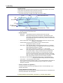
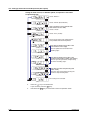
Header Printout (/BT1 Option)
Operation
(Operation
instruction)
1. Chart paper feed
2. Start printout
3. Recording start
(Record start)
Message printout 1
including measured
values
(Message printout 1)
Message printout 2
including measured
values
(Message printout 2)
1. Recording stop
2. End printout
3. Chart paper feed
(Recording stop)
• Example Printout (Dot Model)
End printout
Comment
Batch name (batch number and lot number)
date/time, and chart speed
Message printout 2 including
measured values
Message printout 1 including
measured values
Start printout
Comment
Batch name (batch number and lot number)
date/time, and chart speed
The printout examples may appear differently from the actual printout as a result of functional
improvements made on the recorder after this manual was written.
Start Printout and End printout
You can set “Start printout” and “Start printout 2” for the printout when recording starts.
Also, you can set “End printout” and “End printout 2” for the printout when recording stops.
Printout/Operation
Description
Comment
Prints 32 characters x 5 lines or less.
Notes
Batch name
Batch number
Prints up to 26 characters.
Lot number
Prints a number from 4-digits or 6-digits.
You can automatically increment
by 1 when recording stops.
Date/time
The date format prints out according to the date
printout/display format.
Date and time cannot be turned
On/Off independently.
Chart speed
Prints the current chart paper feed speed.
Chart paper feed
Feeds the chart paper 50 mm or less before Start printout. Steps of 1 mm
Feeds the chart paper 50 mm or less after End printout. Steps of 1 mm
Ejection of pen offset
compensating data
You can record the portion of the data that remains after
recording stops. Also, when recording the remaining
portion of the data, you can change the chart speed to
450 mm/h (fixed).
When pen offset compensating
is On (pen model).
You can select whether to print out the batch name, date/time, and chart speed. By default, the printout is enabled.
For the procedure to set the functions, see section 1.6, “Function Setup Guide.”
IM 04P03B01-01E
1-17
Functional Explanation and Setup Guide
When recording is started, the Start printout is performed, and recording starts. During
trend recording, you can print out messages (up to 5) that include measured values.
When recording is stopped, End printout is performed.
1.3 Recording
• Switching between Start Printout and Start printout 2, and between End printout
and End printout 2
With the remote control function (/R1 option), you can change the items that are
printed out.
For example, when a process ends successfully, End printout is performed and the lot
number is updated. If the process fails, you can have End printout 2 be carried out
and the lot number remain not updated.
Depending on the status of the “batch comment switching signal,” the following
switches occur when the “record start/stop signal” switches:
Batch Comment Switching Signal Status
Level: 0 (Open)
Level: 1 (Closed)
Start printout
Start printout 2
End printout
End printout 2
Record start/Stop Signal Status
Upon start Edge (rising)
Upon stop Edge (falling)
Remote Control Signal
Record start/stop
signal
Start
Stop
Start
Start printout
End printout
Start printout
Stop
Batch comment
switching signal
Concluded
successfully
End printout 2
Concluded
unsuccessfully
Message Printout Including Measured Values
Following the specified message format, the date/time, message strings of the standard
function (5 strings of up to 16 characters), and measured instantaneous values are
printed out together.
• Up to 5 messages of 35 characters can be entered.
• Messages are printed out in the order in which they are set.
• The specified number of characters specified for standard function messages is used,
then if a subsequent character string has been set, it is used next. Also, it can only be
used once for the message format.
Message Example
06/30 10:10 Process-1
134.8°C
Measured value on CH1 (no units)
Character string set for message 1
of the standard function
Date/time
<Related Topics> Setting start printout and stop printout: Sections 4.23 and 3.12
Assigning functions to the remote control input terminals: Section 4.18
Setting the message string: Section 3.8
Enabling the message format: Section 4.23
Regarding the message format: Section 3.13
For the procedure to set the functions, see section 1.6, “Function Setup Guide.”
1-18
IM 04P03B01-01E
1.4
Remote Control Function (/R1 Option)
1
Recorder
Contact
Open collector
Assignable Functions
• Recording start/stop
• Remote input signal: Rising edge signifies start; falling edge signifies stop
• Starts/stops recording.
• Applying a rising edge signal when recording is already in progress produces no
effect. Applying a falling edge signal when recording is stopped produces no effect.
• Chart Speed Switch
• Remote input signal: Level
• The chart paper is fed at the secondary chart speed while a level signal is applied
to the terminal. The secondary chart speed is set in advance.
• Internal Clock Adjustment
• Remote input signal: Trigger
• The internal clock of the recorder is adjusted to the nearest hour depending on the
time when the remote signal is applied.
Time When Signal Is Input
Adjustment
00 min 00 s to 01 min 59 s
Truncates the minutes and seconds.
Example: 10 hours 01 min 50 s becomes 10 hours 00 min 00 s.
02 min 00 s to 57 min 59 s
The time is not changed.
58 min 00 s to 59 min 59 s
Rounds up the minutes and seconds.
Example: 10 hours 59 min 50 s becomes 11 hours 00 min 00 s.
• Message 1 Printout to Message 5 Printout
• Remote input signal: Trigger
• Manual Printout
• Remote input signal: Trigger
• Priority to Remote Recording (/BT1 Option)
• Remote input signal: Edge (rising/start or falling/stop)
• Starts/stops recording.
• When started with a remote signal (on a remote signal rise), stop per key operation
or communication is disabled.
For the procedure to set the functions, see section 1.6, “Function Setup Guide.”
IM 04P03B01-01E
1-19
Functional Explanation and Setup Guide
Specified operations can be carried out by applying remote signals (contact or open
collector signals) to the remote control input terminals.
There are five remote control input terminals. An action can be assigned to each
terminal.
1.4 Remote Control Function (/R1 Option)
• Switching Batch Comment (/BT1 Option)
• Remote input signal: Level
• Switches between Start printout and Start printout 2, and between End printout and
End printout 2 depending on the status of the batch comment switching signal
when recording is started/stopped remotely.
• When starting/stopping by key operation, performs Start printout and End printout.
Remote Signal (Edge, Trigger, and Level)
The above actions are carried out on the rising or falling edge of the remote signal
(edge), the ON signal lasting at least 250 ms (trigger), or the ON/OFF signal (level).
Rising/Falling edge
Rising
Trigger
Level
Falling
250 ms or more
250 ms or more
Operates at the
secondary chart speed
For contact inputs, the remote signal rises when the contact switches from open to
closed and falls when the contact switches from closed to open. For open collector
signals, the remote signal rises when the collector signal (voltage level of the remote
control terminal) goes from high to low and falls when the collector signal goes low to
high.
<Related Topics> Assigning functions to the remote control input terminals: Section 4.18
Setting the secondary chart speed: Section 3.9
For the procedure to set the functions, see section 1.6, “Function Setup Guide.”
1-20
IM 04P03B01-01E
1.5
Other Functions
1
Key lock is a function that prohibits key operations. When key lock is enabled, pressing
keys produces no effect. To release the key lock, a password is entered.
Key Lock Items
Each of the following keys can be included or excluded from the key lock function.
Keys that can be locked
In the case of the FUNC key, each function of the FUNC key can be included or
excluded from the key lock function.
FUNC key functions: Manual printout, list printout, setup list printout, message printout,
printout buffer clear, pen exchange (pen model), and ribbon
cassette exchange (dot model)
<Related Topics> Setting the key lock function: Section 4.9
Using the key lock function: see the Operation Guide)
Customize Menu
The menu can be customized to display only the menus that you use.
• Display only the items that you use on the FUNC key menu.
• Display only the items that you use on the Setting mode menu.
• Lock Basic Setting mode (use a password to enter the mode).
The pen position adjustment (pen model) and dot printing position adjustment (dot
model) can be set so that they can be used without the password.
Hold down
MENU for 3 s
Displays only the
FUNC key menu
items to be used
Basic Setting mode
Setting mode
Operation mode
Displays only the
setup menu items
to be used
Hold down
+
for 3 s
Password
No password
Pen and dot
printing position
adjustment
<Related Topics> Setting the FUNC key menu: Section 4.19
Setting the Setting mode menu: Section 4.20
Enabling/Disabling the customized menu: Section 4.21
Font
The characters used in the printout can be set to English, Japanese, German, or French.
The characters that are available vary depending on the selected font.
English: Alphabet, numbers, and symbols
Japanese: Alphabet, numbers, Katakana, and symbols
German: Alphabet (German), numbers, and symbols
French:
Alphabet (French), numbers, and symbols
<Related Topics> Changing the language: Section 4.13
For the procedure to set the functions, see section 1.6, “Function Setup Guide.”
IM 04P03B01-01E
1-21
Functional Explanation and Setup Guide
Key Lock
1.5 Other Functions
DST
If the recorder is used in a region that has DST, time can be switched automatically
between DST and standard time by setting the date/time when switching from the
standard time to DST and the date/time when switching back from DST to standard time.
When switching from standard time to DST, the clock is set ahead by 1 hour. When
switching back from DST to standard time, the clock is set back by 1 hour.
<Related Topics> Using the DST: Section 3.14
Temperature Unit
The temperature unit can be set to Celsius or Fahrenheit. The setting applies to all
channels.
<Related Topics> Changing the temperature unit: Section 4.24
For the procedure to set the functions, see section 1.6, “Function Setup Guide.”
1-22
IM 04P03B01-01E
1.6
Function Setup Guide
1
Note
This section contains all the settings related to each item. If the desired setting is the same as
the default value, you do not have to set it.
Item
Description
Reference
Section
Date/Time setting
Use CLOCK in Setting mode
2.5
DST
Sets the date/time for switching between DST and standard time using
AUX > DST in Setting mode.
3.14
Setting initialization
Use INIT in Basic Setting mode to initialize the settings of Setting mode
and Basic Setting mode to their default values.
4.17
Measuring input functions
Item
Description
Reference
Section
Range and span of the TC, RTD, or DC voltage
Use RANGE in Setting mode.
2.1
1-5V
• Range, span, and scale
Use RANGE in Setting mode.
• Unit
Use UNIT in setting mode to set the unit after scaling.
• Low-cut
Use PERS. > 1-5V low-cut in Basic Setting mode and select Use or Not.
If Use is selected, turn ON/OFF the low-cut function using RANGE in Setting
mode.
If Not is selected, the Low-cut item does not appear in the RANGE setting.
2.1
• Range, span, and scale
Use RANGE in Setting mode.
• Unit
Use UNIT in setting mode to set the unit after scaling.
2.1
Scaling
2.3
4.15
2.1
2.3
Square Root Computation • Range, span, and scale
Use RANGE in Setting mode.
• Unit
Use UNIT in setting mode to set the unit after scaling.
• Low-cut
Use PERS. > SQRT low-cut in Basic Setting mode and select Use or Not.
If Use is selected, set the low-cut value using RANGE in Setting mode.
If Not is selected, the Low-cut item does not appear in the RANGE setting.
2.1
Unused channels
Use RANGE > SKIP in Setting mode to disabling the trend recording (dot model)
and periodic printout of the target channel.
2.1
Bias
Use PERS. > BIAS in Basic Setting mode and select Use or Not.
If Use is selected, set the bias value that is added to the input using BIAS in
Setting mode. If Not is selected, the BIAS item does not appear.
4.15
3.10
Calibration Correction (/CC1 option)
Use PERS. > CALIB in Basic Setting mode and select Use or Not
If Use is selected,
• Use CALIB in Basic Setting mode to set the correction mode and the number
of calibration points.
• Use CALIB in Setting mode to set the measured value and correction value
for each channel.
If Not is selected, the CALIB item does not appear.
Burnout detection function (TC input and 1-5V input)
Use B_OUT in Basic Setting mode to set the burnout detection function for each
channel.
IM 04P03B01-01E
2.3
4.15
2.1
4.15
4.22
3.11
4.3
1-23
Functional Explanation and Setup Guide
This section explains the settings necessary to use various functions of the recorder.
Read the section corresponding to the function you wish to use.
1.6 Function Setup Guide
Item
Description
Reference
Section
RJC of TC input
Use RJC in Basic Setting mode to select whether to use the internal
RJC function or an external RJC function.
4.4
Filter (pen model)
Use FILTR in Basic Setting mode and select Use or Not.
If Use is selected, set the filter time constant using AUX > FILTR in Setting mode.
If Not is selected, the AUX > FILTR item does not appear.
4.11
3.2
Moving average (dot model)
Use M_AVE in Basic Setting mode and select Use or Not.
If Use is selected, set the number of samples of moving average using AUX >
M_AVE in Setting mode.
If Not is selected, the AUX > M_AVE item does not appear.
4.10
3.3
Integration time of the A/D converter
Use INTG in Basic Setting mode to set the integration time of the A/D converter.
4.2
Temperature Unit
Select the temperature unit using TEMP in Basic Setting mode.
4.24
Item
Description
Reference
Section
Alarms for each channel
Use ALARM in Setting mode.
2.2
Alarm functions
Set a hysteresis on the alarm occurrence/release value of high limit alarm and low limit alarm
Use ALARM > HYS in Basic Setting mode to set the hysteresis to be applied
to the high limit alarm and low limit alarm of measurement channels.
4.1
Diagnosis output
4.1
Use ALARM > DIAG in Basic Setting mode to set the function.
Change the alarm output relay operation
If ALARM > RELAY in Basic Setting mode set to “DE_EN”, alarm output relay is
energized during normal operation and de-energized when an alarm occurs.
4.1
Recording functions
Item
Description
Recording interval (dot model)
Use AUX > TREND in Setting mode to set the recording interval to AUTO or FIX.
Reference
Section
3.1
Change the recording color of measurement channels (dot model).
Use COLOR in Basic Setting mode to set the recording color of measurement
channels.
4.5
Turn trend recording ON/OFF (dot model)
Use AUX > PRINT in Setting mode to turn ON/OFF the trend recording for each
measurement channel.
3.6
Chart speed
2.4
Use CHART in Setting mode to set the chart speed.
Record by setting recording zone
Use AUX > ZONE in Setting mode to set the recording zone for each channel.
Partial expanded recording Use PART in Basic Setting mode and select Use or Not.
If Use is selected, set the display mode using AUX > PART in Setting mode.
If Not is selected, the AUX > PART item does not appear.
3.4
4.12
3.5
Record by compensating for the pen offset along the time axis (pen model)
Use POC in Setting mode to turn ON/OFF offset compensation.
4.6
Date format
Use DATE in Basic Setting mode to set the printout/display format
of the date.
4.14
Time format
Use T_PRN in Basic Setting mode to set the printout format of the time.
4.16
1-24
IM 04P03B01-01E
1.6 Function Setup Guide
Item
Description
1
Functional Explanation and Setup Guide
Reference
Section
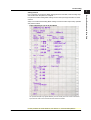
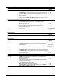
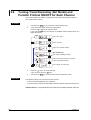
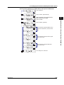
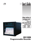
Periodic printout
Mar.31.2006!
15:50*
1
1.000V
2
-1.000V
0.000
1
RED
50mm/h_
Channel number
or tag
Measured value
2.000
V
Scale
Recording color
(pen model)
• Enable/Disable the periodic printout
Use PER. in Basic Setting mode to turn ON/OFF the periodic printout.
• Printout interval
Use PER. in Basic Setting mode to set the periodic printout interval.
• Turn ON/OFF periodic printout for each channel
Use AUX > PRINT in Setting mode to turn ON/OFF the periodic printout for
each measurement channel.
• Scale printout and recording color printout (pen model)
Use PRINT > SCALE in Basic Setting mode to turn scale printout ON/OFF.
Use PRINT > PEN color in Basic Setting mode to turn pen color printout
ON/OFF (pen model).
Tag printout
• Select channel printout or tag printout
Use PRINT > TAG.CH in Basic Setting mode to select whether to use channel
numbers or tags in printouts.
• Set the tag
Use AUX > TAG in Setting mode to set the tag name.
4.8
4.8
3.6
4.7
4.7
3.7
Alarm occurrence/release printout
• Turn printout ON/OFF
4.7
Use PRINT > ALARM in Basic Setting mode to select whether to print the alarm
occurrence and release, print only the alarm occurrence, or not print.
• Time printout format
4.16
Use T_PRN > ALARM in Basic Setting mode to set the time printout format
when printing alarm occurrence/release.
Message printout
• Set the message string
3.8
Use AUX > MSG to set the message string to be printed.
• Time printout format
4.16
Use T_PRN > MSG in Basic Setting mode to set the time printout format.
• Execute the message printout
Operation Guide
Use FUNC key > MSG in Operation mode to execute the message printout. Printing a Message
New chart speed printout
• Turn printout ON/OFF
Use PRINT > SPEED in Basic Setting mode to set whether to print the new
chart speed when the chart speed is changed.
• Time printout format
Use T_PRN > SPEED in Basic Setting mode to set the time printout format.
4.7
• Turn printout ON/OFF
Use PRINT > RCD in Basic Setting mode to enable/disable the recording
start printout.
• Time printout format
Use T_PRN > RCD in Basic Setting mode to set the time printout format.
4.7
Recording Start Printout
Setting Start printout/End printout (/BT1 option)
Use BATCH > DUAL (Dual comment) in Basic Setting mode, and select a LOT
from 4 or 6 digits.
Use BATCH > B.NUM in Setting mode to set the batch number.
Use BATCH > LOT in Setting mode to set the lot number.
Use BATCH > DETAI > START, END, STAT2, and END2 in Setting mode to set
the various comments, printout ON/OFF, and chart paper feed amount for each.
Also, in END and END2, enter the settings for lot number update and ejection of
pen offset compensating data (Pen model).
IM 04P03B01-01E
4.16
4.16
4.23
3.12
3.12
3.12
1-25
1.6 Function Setup Guide
Item
Description
Reference
Section
Switching between Start printout and Start printout 2, and between End printout and End printout 2 (/BT1, /R1 option)
• Switching settings
Assign DUAL (Batch comment switching) to the remote control input terminal.
4.18
Use BATCH > DUAL (Dual comment) in Basic Setting mode and select Use.
4.23
Set BATCH > DETAI > STAT2, and END2 in Setting mode.
3.12
• Executing the switch
The switch occurs according to the status of the DUAL (Batch comment
1.3
switching) signal when RCD or PR.RCD signal assigned to the remote control
input terminal rises or falls.
Printout of messages including measured values (/BT1 option)
• Setting message strings
Use AUX > MSG in Setting mode to enter the message to print out.
• Setting the message format
Use BATCH > MSG_F in Basic Setting mode and select Use.
Set the message format using the PC software (sold separately) or a
communication command.
• Executing the message printout
Execute the message printout by choosing FUNC key > MSG in
Operation mode.
3.8
4.23
Operation Guide
Printing a Message
Display functions
Item
Description
Reference
Section
Date format
Same as the Date format in “Recording functions.”
4.14
Item
Description
Reference
Section
Key lock
• Target keys and password
Use LOCK in Basic Setting mode to set the keys to be key-locked and the
password.
• Enable the key lock
Use FUNC key > LOCK in Operation mode to turn key lock ON/OFF.
4.9
Other functions
Operation Guide
Activating/Releasing
the Key Lock
Customize menu
• FUNC key target menu selection
4.19
Use S.MENU > FUNC in Basic Setting mode to select the menus to be displayd.
• Setting mode target menu selection
4.20
Use S.MENU > SET in Basic Setting mode to select the menus to be displayd.
• Customize menu execution
4.21
Use CUST.M in Basic Setting mode to select whether to use the customized menu.
Font
Use FONT in Basic Setting mode to set the characters used in the recording.
4.13
Remote control function
(/R1 option)
• Assign functions to the remote control input terminals
Use REM in Basic Setting mode to set the function to be assigned to the
remote control input terminal.
• Secondary chart speed
If “chart speed switching” is assigned, use AUX > SPD_2 in Setting mode to
set the secondary chart speed.
• Switching between Start printout and Start printout 2, and between End
printout and End printout 2 (/BT1 option)
If DUAL (Batch comment switching) is assigned,
Use BATCH > DUAL (Dual comment) in Basic Setting mode. Set BATCH >
DETAI > STAT2, and END2 in Setting mode.
4.18
1-26
3.9
4.23
3.12
IM 04P03B01-01E
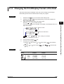
Chapter 2 Frequently Used Setup Operations (Setting Mode)
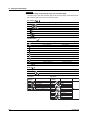
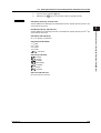
2.1
Setting the Input Range
Input range can be set for each measurement channel. Set unused channels to Skip.
If you change the input range, set the bias, alarm, partial expanded recording, and
calibration correction again.
2
TC, RTD, and DC Voltage
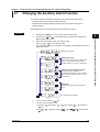
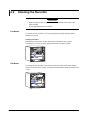
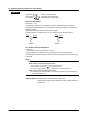
1.
2.
Hold down the MENU key for 3 seconds to enter Setting mode.
Carry out the procedure shown in the figure below.
Press the
or
key to select the value.
For the procedure on how to enter values or characters, see page 19 in the
Operation Guide.
To change the polarity, press the
or
key when the leftmost digit of the
value is blinking.
If you press the
key, the operation is cancelled, and the display returns to a
higher level menu.
Select “RANGE.”
(RANGE)
Select the channel number.
(CH1)
Select the input type.
(TC)
Channel number
Select the range.
(R)
Set the left span value.
Span left
Set the right span value.
Span right
The settings are activated.
(OK)
3.
4.
IM 04P03B01-01E
Press the
key to set other channels.
If you are done, press the
key.
Hold down the MENU key for 3 seconds to return to Operation mode.
2-1
Frequently Used Setup Operations (Setting Mode)
Procedure
2.1 Setting the Input Range
Description
• Selectable Range of Input Range, Span Left, and Span Right
The input range, span left, and span right can be set in the range shown below. Span
left and span right cannot be set to the same value.
DC voltage (
)
Range Type
Selectable Span Range
20 mV(
)
60 mV(
)
200 mV(
–20.00 to 20.00 mV
–60.00 to 60.00 mV
)
2 V(
)
6 V(
)
–200.0 to 200.0 mV
–2.000 to 2.000 V
–6.000 to 6.000 V
20 V(
)
–20.00 to 20.00 V
50 V(
)
–50.00 to 50.00 V
Thermocouple (
)
Range Type
Selectable Span Range (°C)
Selectable Span Range (°F)
R(
)
0.0 to 1760.0°C
32 to 3200°F
S(
)
0.0 to 1760.0°C
32 to 3200°F
B(
)
0.0 to 1820.0°C
32 to 3308°F
K(
)
–200.0 to 1370.0°C
–328 to 2498°F
E(
)
–200.0 to 800.0°C
–328.0 to 1472.0°F
J(
)
–200.0 to 1100.0°C
–328.0 to 2012.0°F
T(
)
–200.0 to 400.0°C
–328.0 to 752.0°F
N(
)
0.0 to 1300.0°C
32 to 2372°F
W(
)
0.0 to 2315.0°C
32 to 4199°F
L(
)
–200.0 to 900.0°C
–328.0 to 1652.0°F
U(
)
–200.0 to 400.0°C
–328.0 to 752.0°F
0.0 to 2400.0°C
32 to 4352°F
Selectable Span Range (°C)
Selectable Span Range (°F)
–200.0 to 600.0°C
–328.0 to 1112.0°F
–200.0 to 550.0°C
–328.0 to 1022.0°F
WRe (
)
RTD (
)
Range Type
PT (Pt100) (
JPT(JPt100) (
)
)
/N1 option
Selectable
Settings
Cu1
Cu2
Cu3
Cu4
Cu5
Cu6
Cu25
2-2
Input Type
Cu10 (GE)
Cu10 (L&N)
Cu10 (WEED)
Cu10 (BAILEY)
Cu10: a = 0.00392 at 20°C
Cu10: a = 0.00393 at 20°C
Cu25*: a = 0.00425 at 0°C
/N3 option
Selectable
Setting
PR
PLATI
NiMo
W/WRe
N2
Kp
Pt4
Pt3
Ni1
Ni2
Ni3
J263
Cu8
Cu9
Input Type
Notes
PR40-20
Thermocouple
PLATINEL
NiNiMo
W/WRe26
Type N (AWG14)
Kp vs Au7Fe
Pt25
RTD
Pt50
Ni100 (SAMA)
Ni100 (DIN)
Ni120
J263*B
Cu53
Cu100: a = 0.00425 at 0°C
IM 04P03B01-01E
2.1 Setting the Input Range
1-5V Input
Select “RANGE.”
(RANGE)
2
Select the channel number.
Select “1-5V.”
(1-5V)
Channel number
Set the left span value.
Span left
Set the right span value.
Span right
Select the left scale value and the decimal place.
Scale left Decimal point
Select the right scale value.
Scale right
(When low-cut is enabled)
Select whether to use low-cut.
(ON)
Low-cut
The settings are activated.
(OK)
Description
• Span Left and Span Right
Selectable span left range: 0.8 to 1.2 V
Selectable span right range: 4.8 to 5.2 V
• Scale Left, Scale Right, and Decimal Place
Selectable range (mantissa): –19999 to 30000
Example: The value in the range of –100.00 to 350.00 cannot be specified. The
mantissa of scale right is 35000, which exceeds the upper limit to 30000.
Set in the range of –100.0 to 350.0.
Decimal place: XXXXX, XXXX.X, XXX.XX, XX.XXX, X.XXXX
To set the decimal place for the left scale setup item, press the
key to make
blink, then press the
or
key.
The decimal position is the position specified by scale left.
Make sure that left scale is less than scale right.
• Low-Cut
ON (
):
OFF (
):
Cuts values less than or equal to 0% of the recording span (sets
such values to 0% (scale left value)).
Does not apply the low-cut function.
<Related Topics> Setting the unit: Section 2.3
Enabling the low-cut function: Section 4.15
IM 04P03B01-01E
2-3
Frequently Used Setup Operations (Setting Mode)
(CH1)
2.1 Setting the Input Range
Linear Scaling
Select “RANGE.”
(RANGE)
Select the channel number.
(CH1)
Select “SCALE.”
(SCALE)
Channel number
Select the input type.
(VOLT)
Select the range.
(2V)
Set the left span value.
Span left
Set the right span value.
Span right
Select the left scale value and the decimal place.
Scale left
Decimal point
Select the right scale value.
Scale right
The settings are activated.
(OK)
Description
• Span Left and Span Right
Same as the selectable span range of the DC voltage, Thermocouple, and RTD
range.
• Scale Left, Scale Right, and Decimal Place
Selectable range (mantissa): –19999 to 30000
Example: The value in the range of –100.00 to 350.00 cannot be specified. The
mantissa of scale right is 35000, which exceeds the upper limit to 30000.
Set in the range of –100.0 to 350.0.
Decimal place: XXXXX, XXXX.X, XXX.XX, XX.XXX, X.XXXX
To set the decimal place for the left scale setup item, press the
key to make
blink, then press the
or
key.
The decimal position is the position specified by scale left.
<Related Topics> Setting the unit: Section 2.3
2-4
IM 04P03B01-01E
2.1 Setting the Input Range
Delta Computation
Select “RANGE.”
(RANGE)
2
Select the channel number.
Frequently Used Setup Operations (Setting Mode)
(CH2)
Select “DELTA.”
(DELTA)
Channel number
Select the reference channel.
(CH1)
Set the left span value.
Span left
Set the right span value.
Span right
The settings are activated.
(OK)
Description
• Reference Channel
The reference channel must be a channel that is smaller in channel number than the
channel being set.
• Span Left and Span Right
The range type is the same as the reference channel. The span left and span right
can be set in the range shown below. Span left and span right cannot be set to the
same value.
Input Type
Range Type
DC voltage
(
)
20 mV (
60 mV (
200 mV (
2V(
)
6V(
)
20 V (
50 V (
Selectable Span Range (°C)
)
)
)
)
Thermocouple R ( )
(
)
S( )
B( )
K( )
E( )
J( )
T( )
N( )
W( )
L( )
U( )
WRe (
RTD
(
IM 04P03B01-01E
)
PT(Pt100) (
JPT(JPt100) (
Selectable Span Range (°F)
–20.00 to 20.00 mV
–60.00 to 60.00 mV
) –200.0 to 200.0 mV
–2.000 to 2.000 V
–6.000 to 6.000 V
–20.00 to 20.00 V
–50.00 to 50.00 V
)
)
)
–1760.0 to 1760.0°C
–1760.0 to 1760.0°C
–1820.0 to 1820.0°C
–1570.0 to 1570.0°C
–1000.0 to 1000.0°C
–1300.0 to 1300.0°C
–600.0 to 600.0°C
–1300.0 to 1300.0°C
–1999.9 to 2315.0°C
–1100.0 to 1100.0°C
–600.0 to 600.0°C
–1999.9 to 2400.0°C
–3168 to 3168°F
–3168 to 3168°F
–3276 to 3276°F
–2826 to 2826°F
–1800 to 1800°F
–1999.9 to 2340.0°F
–1080.0 to 1080.0°F
–2340 to 2340°F
–4167 to 4167°F
–1980 to 1980°F
–1080.0 to 1080.0°F
–4320 to 4320°F
–800.0 to 800.0°C
–750.0 to 750.0°C
–1440.0 to 1440.0°F
–1350.0 to 1350.0°F
2-5
2.1 Setting the Input Range
ON/OFF Input
Select “RANGE.”
(RANGE)
Select the channel number.
(CH1)
Select “DI.”
(DI)
Channel number
Select contact or level.
(CONT)
Set the left span value.
Span left
Set the right span value.
Span right
The settings are activated.
(OK)
Description
• Selectable Range of Input Range, Span Left, and Span Right
The input range, span left, and span right can be set in the range shown below. Span
left and span right cannot be set to the same value.
Range Type
2-6
Selectable Span Values
Level (
)
0: Less than 2.4 V, 1: 2.4 V or higher, within ±6 V
Contact (
)
0: Open, 1: Closed
IM 04P03B01-01E
2.1 Setting the Input Range
Square Root Computation
Select “RANGE.”
(RANGE)
2
Select the channel number.
Select “SQRT.”
(SQRT)
Channel number
Select from the range types of DC voltage.
20 mV, 60 mV, 200 mV, 2 V, 6 V, 20 V, or 50 V
(2V)
Set the left span value.
Span left
Set the right span value.
Span right
Select the left scale value and the decimal place.
Scale left Decimal point
Select the right scale value.
Scale right
(ON)
(Displays the following when the low-cut
is enabled)
Turn ON or OFF the low-cut function.
Low-cut
Set the low-cut point.
0.0 to 5.0% of the recording span, 0.1 steps.
The settings are activated.
(OK)
Description
• Input Type on Which Square Root Computation Can Be Performed
Square root computation can be performed when set to DC voltage input.
• Span Left and Span Right
Same as the selectable span range of the DC voltage range.
Make sure that span left is less than span right.
• Scale Left, Scale Right, and Decimal Place
Selectable range (mantissa): –19999 to 30000
Example: The value in the range of –100.00 to 350.00 cannot be specified. The
mantissa of scale right is 35000, which exceeds the upper limit to 30000.
Set in the range of –100.0 to 350.0.
Decimal place: XXXXX, XXXX.X, XXX.XX, XX.XXX, X.XXXX
To set the decimal place for the left scale setup item, press the
key to make
blink, then press the
or
key.
The decimal position is the position specified by scale left.
Make sure that scale left is less than scale right.
IM 04P03B01-01E
2-7
Frequently Used Setup Operations (Setting Mode)
(CH1)
2.1 Setting the Input Range
• Low-Cut and Low-Cut Point
If low-cut is set to ON, set the low-cut point.
Selectable range of the low-cut point: 0.0 to 5.0% of the recording span
Values below the low-cut point is set to 0% of the recording span (scale left value).
<Related Topics> Setting the unit: Section 2.3
Enabling the low-cut function: Section 4.15
Skip (Unused Channels)
Select “RANGE.”
(RANGE)
Select the channel number.
(CH1)
Select “SKIP.”
(SKIP)
Channel number
The settings are activated.
(OK)
Note
Do not use channels set to skip as a reference channel of delta computations.
2-8
IM 04P03B01-01E
2.2
Setting the Alarm
An alarm can be set for each channel.
If you change the input range, set the alarm again.
2
1.
2.
Hold down the MENU key for 3 seconds to enter Setting mode.
Carry out the procedure shown in the figure below.
Press the
or
key to select the value.
For the procedure on how to enter values or characters, see page 19 in the
Operation Guide.
To change the polarity, press the
or
key when the leftmost digit of the
value is blinking.
If you press the
key, the operation is cancelled, and the display returns to a
higher level menu.
Select the “ALARM.”
(ALARM)
Select the channel number.
(CH1)
Select the level number between 1 and 4.
(L4)
Channel number
Select ON to set the alarm.
(ON)
Level number
(H)
(Displays the following when the alarm
is ON)
Select the alarm type.
Set the value used to turn ON the alarm.
(ON)
Select ON to set the alarm relay output.
This setting is valid only on models with
the /A1, /A2, or /A3 option.
Relay output
(When the alarm output is ON)
Specify the alarm output relay number.
(I01)
The settings are activated.
(OK)
3.
4.
IM 04P03B01-01E
Press the
key to set other channels.
If you are done, press the
key.
Hold down the MENU key for 3 seconds to return to Operation mode.
2-9
Frequently Used Setup Operations (Setting Mode)
Procedure
2.2 Setting the Alarm
Explanation
Alarm Type
Symbol
Name
H(
)
High limit alarm
L(
)
Low limit alarm
h(
)
Difference high limit alarm
Can be specified on channels set to delta computation.
Difference low limit alarm
Can be specified on channels set to delta computation.
l(
)
Notes
Note
On channels set to delta computation, alarms can be detected on the values illustrated in the
figure below.
Alarm on a channel set to delta computation
Alarm
H, L
Alarm
h, l
Input value
Measured value
−
Measured value on the reference channel
Alarm Value
• High Limit Alarm/Low Limit Alarm
The following values can be specified.
• For DC voltage, thermocouple, or RTD:
Values within the measurable range in the input range (example: –2.000 to
2.000 V for the 2 V input range).
• For ON/OFF input (DI): 0 or 1.
• For linear scaling (1-5V, scaling, and square root):
A value within –5 to 105% of the scaling span and within the range of
–19999 to 30000 (excluding the decimal point).
• Difference High Limit Alarm/Difference Low Limit Alarm
Values in the measurable range can be specified.Measurable range refers to
“Selectable Span Range” in the table on page 2-5.
Relay No.
The selectable relay numbers are listed below.
I01 and I02 on the /A1 option
I01, I02, I03, and I04 on the /A2 option
I01, I02, I03, I04, I05, and I06 on the /A3 option
<Related Topics> Setting the auxiliary alarm function: Section 4.1
2-10
IM 04P03B01-01E
2.3
Setting the Unit on Linearly Scaled Channels
Units can be assigned on channels whose input range is set to Scale, 1-5V, or
SQRT.The assigned unit is added when printing to the chart paper or during data
transmission.
2
1.
2.
Hold down the MENU key for 3 seconds to enter Setting mode.
Carry out the procedure shown in the figure below.
Press the
or
key to select the value.
For the procedure on how to enter values or characters, see page 19 in the
Operation Guide.
If you press the
key, the operation is cancelled, and the display returns to a
higher level menu.
Select “UNIT.”
(UNIT)
For English
Lower
Upper
0 1
2 3
4 5
6 7 8
#
3
C
S
c
s
%
5
E
U
e
u
(
8
H
X
h
x
20 SP
30
0 1 2
40 @ A B
P Q R
a b
70 p q r
50
60
4
D
T
d
t
6
F
V
f
v
7
G
W
g
w
9 A B C D E F
)
9
I
Y
i
y
∗ +
−
.
(CH1)
J K L M N O
Z
°
j k l m n o
z µ Ω 2 3
0
1 2 3
#
0 1 2 3
40 @ A B C
50 P Q R S
a b c
60
70 p q r s
4 5
20 SP
30
4
D
T
d
t
%
5
E
U
e
u
6 7 8
6
F
V
f
v
7
G
W
g
w
(
8
H
X
h
x
2
3
)
9
I
Y
i
y
∗ +
-
.
/
J K L M N O
Z
\
j k l m n o
z
Ω
D0
E0
à
â
F0
2nd char. 2nd character ASCII code
Enter the ASCII code of the 3rd
character.
3rd character ASCII code
:
:
µ
Ä
C0
Enter the ASCII code of the 2nd
character.
9 A B C D E F
A0
B0 °
Enter the ASCII code of the 1st
character.
1st char. 1st character ASCII code
For German or French
Lower
Upper
Select the channel number.
/
ä
ô
Ë
Ç
Ö
Ü
ö
ç è é ê ë
ù
û ü
Ï
ß
î ï
Enter the ASCII code of the 6th
character.
6th character ASCII code
Only German
Only French
The settings are activated.
SP = Space
Example: To register A, enter 41.
(OK)
3.
4.
Press the
key to set other channels.
If you are done, press the
key.
Hold down the MENU key for 3 seconds to return to Operation mode.
Explanation
Characters That Can Be Used for Units
A unit is set using up to six characters.
IM 04P03B01-01E
2-11
Frequently Used Setup Operations (Setting Mode)
Procedure
2.4
Changing the Chart Speed
The chart speed can be changed.
Procedure
1.
2.
Hold down the MENU key for 3 seconds to enter Setting mode.
Carry out the procedure shown in the figure below.
Press the
or
key to select the value.
If you press the
key, the operation is cancelled, and the display returns to a
higher level menu.
Select the “CHART.”
(CHART)
Select the chart speed.
The settings are activated.
(OK)
3.
4.
If you are done, press the
key.
Hold down the MENU key for 3 seconds to return to Operation mode.
Explanation
Chart Speed
• Pen model:
• Dot model:
Select from the 40 settings shown below.
Select from the 28 settings in the thick frame shown below.
Chart speed (the chart speed of the dot model is inside the thick frame)
10
90
375
3000
15
100
450
3600
20
120
600
4500
25
150
720
4800
30
160
750
5400
40
180
900
6000
50
200
1200
7200
60
240
1500
9000
(Unit: mm/h)
75
80
300
1800
10800
360
2400
12000
<Related Topics> Setting the secondary chart speed: Section 3.9
Turning the new chart speed printout ON and OFF: Section 4.7
2-12
IM 04P03B01-01E
2.5
Setting the Date/Time
The date/time can be set.
2
1.
2.
Hold down the MENU key for 3 seconds to enter Setting mode.
Carry out the procedure shown in the figure below.
Press the
or
key to select the value.
For the procedure on how to enter values or characters, see page 19 in the
Operation Guide.
If you press the
key, the operation is cancelled, and the display returns to a
higher level menu.
Select “CLOCK.”
(CLOCK)
Set the year, month, and day.
Year
Month
Day
Sets the hour, minute, and second.
Hour
Minute
Second
The settings are activated.
(OK)
3.
4.
If you are done, press the
key.
Hold down the MENU key for 3 seconds to return to Operation mode.
Explanation
Date/Time
Set the lower two digits of the year.
Values in the range 80 and 99 correspond to 1980 to 1999.
Note
When setting the date/time, the year, month, day, hour, minute, and second are displayed in the
order shown above regardless of the printout/display format of the date (see section 4.14).
<Related Topics> Changing the printout/display format of the date: Section 4.14
Changing the printout format of the time: Section 4.16
IM 04P03B01-01E
2-13
Frequently Used Setup Operations (Setting Mode)
Procedure
Chapter 3
3.1
Setup Operations for Convenient Functions (Setting Mode)
Setting the Trend Recording Interval (Dot
Model)
The trend recording interval (dot printing interval) on the dot model can be set.
Procedure
1.
2.
Select the “AUX.”
(AUX)
Select “TREND.”
(TREND)
Set the dot printing interval to AUTO or FIX.
(AUTO)
The settings are activated.
(OK)
3.
4.
If you are done, press the
key.
Hold down the MENU key for 3 seconds to return to Operation mode.
Explanation
Trend Recording Interval
): The trend recording interval is set according to the chart speed so
AUTO (
that the dots do not overlap.
FIX (
):
The trend recording interval is fixed to 10 s/6 dots.
When set to AUTO
When set to FIX
Dot
Recording Intervals When AUTO Is Selected
Chart speed
Integration Time Set to 50Hz/60Hz/AUTO Integration Time Set to 100 ms
10 mm/h
90 s
90 s
15 mm/h
60 s
60 s
20 mm/h
45 s
45 s
25 mm/h
36 s
35 s
30 mm/h
30 s
30 s
40 mm/h
22 s
22.5 s
50 mm/h
18 s
17.5 s
60 mm/h
15 s
15 s
75 mm/h
12 s
10 s
80 mm/h
11 s
10 s
90 mm/h or higher
10 s
10 s
IM 04P03B01-01E
3-1
3
Setup Operations for Convenient Functions (Setting Mode)
Hold down the MENU key for 3 seconds to enter Setting mode.
Carry out the procedure shown in the figure below.
Press the
or
key to select the value.
If you press the
key, the operation is cancelled, and the display returns to a
higher level menu.
3.2
Setting the Filter (Pen Model)
A filter can be set on the measurement channels on the pen model.
Procedure
1.
2.
Hold down the MENU key for 3 seconds to enter Setting mode.
Carry out the procedure shown in the figure below.
Press the
or
key to select the value.
If you press the
key, the operation is cancelled, and the display returns to a
higher level menu.
Select the “AUX.”
(AUX)
Select “FILTR.”
(FILTR)
Select the channel number.
(CH1)
Select the filter time constant.
(OFF)
Channel number
The settings are activated.
(OK)
3.
4.
Press the
key to set other channels.
If you are done, press the
key.
Hold down the MENU key for 3 seconds to return to Operation mode.
Explanation
Filter Time Constant
The time constant is selectable from 2 s, 5 s, and 10 s. Select OFF when not using the
filter.
<Related Topics> Enabling the filter function: Section 4.11
3-2
IM 04P03B01-01E
3.3
Setting the Moving Average (Dot Model)
The moving average function can be set on the measurement channels on the dot
model.
Procedure
1.
2.
Select the “AUX.”
(AUX)
Select “M_AVE.”
(M_AVE)
Select the channel number.
(CH1)
Select the number of samples of the
moving average.
(OFF)
Channel number
The settings are activated.
(OK)
3.
4.
Press the
key to set other channels.
If you are done, press the
key.
Hold down the MENU key for 3 seconds to return to Operation mode.
Explanation
Number of Samples of Moving Average
The number of samples can be set to an integer between 2 and 16. Select OFF when
not using the moving average function.
<Related Topics> Enabling the moving average: Section 4.10
IM 04P03B01-01E
3-3
3
Setup Operations for Convenient Functions (Setting Mode)
Hold down the MENU key for 3 seconds to enter Setting mode.
Carry out the procedure shown in the figure below.
Press the
or
key to select the value.
If you press the
key, the operation is cancelled, and the display returns to a
higher level menu.
3.4
Setting Recording Zones for Each Channel
(Zone Recording)
A recording zone can be set for each measurement channel.
Procedure
1.
2.
Hold down the MENU key for 3 seconds to enter Setting mode.
Carry out the procedure shown in the figure below.
Press the
or
key to select the value.
For the procedure on how to enter values or characters, see page 19 in the
Operation Guide.
If you press the
key, the operation is cancelled, and the display returns to a
higher level menu.
Select the “AUX.”
(AUX)
Select “ZONE.”
(ZONE)
Select the channel number.
(CH1)
Channel number
Set the leftmost position of the recording
zone.
Leftmost position
Set the rightmost position of the recording
zone.
Rightmost position
The settings are activated.
(OK)
3.
4.
Press the
key to set other channels.
If you are done, press the
key.
Hold down the MENU key for 3 seconds to return to Operation mode.
Explanation
Recording Zone
The recording zone can be set in the following range.
Leftmost position: 0 mm to 95 mm
Rightmost position: 5 mm to 100 mm
Set a larger value for the rightmost position than the leftmost position.
Set at least 5 mm for the recording zone width.
Note
If the recording zone is set to a value less than 40 mm, scale printout of periodic printout cannot
be executed.
3-4
IM 04P03B01-01E
3.5
Setting the Partial Expanded Recording
A section of the recording range can be expanded.
If you change the input range, set the partial expanded recording again.
Procedure
1.
2.
Select the “AUX.”
(AUX)
Select the “PART.”
(PART)
Select the channel number.
(CH1)
Select ON to set the partial expanded
recording function.
(ON)
Channel number
(When partial expanded recording is ON)
Set the boundary position. (A value when
the record span is assumed to be 100%)
Boundary position
Set the boundary value within the
recording span.
Boundary value
The settings are activated.
(OK)
3.
4.
Press the
key to set other channels.
If you are done, press the
key.
Hold down the MENU key for 3 seconds to return to Operation mode.
Explanation
Boundary Position
Set a value between 1 and 99%. One percent corresponds to 1 mm, because the record
width is 100 mm.
Example: To record 0 to 8 V in the 0 to 50% position and 8 to 10 V in the 50% to 100%
position with a span of 0 to 10 V, set the boundary position to 50% and the
boundary value to 8.00 V.
<Related Topics> Enabling the partial expanded recording function: Section 4.12
IM 04P03B01-01E
3-5
3
Setup Operations for Convenient Functions (Setting Mode)
Hold down the MENU key for 3 seconds to enter Setting mode.
Carry out the procedure shown in the figure below.
Press the
or
key to select the value.
For the procedure on how to enter values or characters, see page 19 in the
Operation Guide.
To change the polarity, press the
or
key when the leftmost digit of the
value is blinking.
If you press the
key, the operation is cancelled, and the display returns to a
higher level menu.
3.6
Turning Trend Recording (Dot Model) and
Periodic Printout ON/OFF for Each Channel
This section explains the details of setting the trend recording and periodic printout for
each measurement channel.
Procedure
1.
2.
Hold down the MENU key for 3 seconds to enter Setting mode.
Carry out the procedure shown in the figure below.
Press the
or
key to select the value.
key, the operation is cancelled, and the display returns to a
If you press the
higher level menu.
Select the “AUX.”
(AUX)
Select “PRINT.”
(PRINT)
Select the channel number.
(CH1)
(Dot model only)
Turn trend recording ON/OFF.
(ON)
Trend recording
Select whether to print the measured
values in periodic printout.
(ON)
Periodic printout
The settings are activated.
(OK)
3.
4.
Press the
key to set other channels.
If you are done, press the
key.
Hold down the MENU key for 3 seconds to return to Operation mode.
Explanation
The following settings can be entered for each channel.
• Turn trend recording ON/OFF (dot model only).
• Yurn the printing of measured values/alarm statuses ON/OFF during periodic printout.
<Related Topics> Turning Periodic Printout ON and OFF and Setting the Interval: Section 4.8
3-6
IM 04P03B01-01E
3.7
Setting Tags on Channels
Tags can be assigned to measurement channels.
Procedure
1.
2.
Select the “AUX.”
(AUX)
Select “TAG.”
(TAG)
For English
Lower
Upper
0 1
2 3
4 5
6 7 8
#
3
C
S
c
s
%
5
E
U
e
u
(
8
H
X
h
x
20 SP
30
0 1 2
40 @ A B
P Q R
a b
70 p q r
50
60
4
D
T
d
t
6
F
V
f
v
7
G
W
g
w
9 A B C D E F
)
9
I
Y
i
y
∗ +
−
.
(CH1)
J K L M N O
Z
°
j k l m n o
z µ Ω 2 3
0
1 2 3
#
0 1 2 3
40 @ A B C
50 P Q R S
a b c
60
70 p q r s
4 5
20 SP
30
4
D
T
d
t
%
5
E
U
e
u
6 7 8
6
F
V
f
v
7
G
W
g
w
(
8
H
X
h
x
)
9
I
Y
i
y
∗ +
-
.
/
J K L M N O
Z
\
j k l m n o
z
Ω
2nd char. 2nd character ASCII code
Enter the ASCII code of the 3rd
character.
3rd character ASCII code
°
2
3
D0
à
â
F0
:
:
µ
Ä
C0
E0
Enter the ASCII code of the 2nd
character.
9 A B C D E F
A0
B0
Enter the ASCII code of the 1st
character.
1st char. 1st character ASCII code
For German or French
Lower
Upper
Select the channel number.
/
ä
ô
Ë
Ç
Ö
Ü
ö
ç è é ê ë
ù
û ü
Ï
ß
î ï
Enter the ASCII code of the 7th
character.
7th character ASCII code
Only German
Only French
The settings are activated.
SP = Space
Example: To register A, enter 41.
(OK)
3.
4.
Press the
key to set other channels.
If you are done, press the
key.
Hold down the MENU key for 3 seconds to return to Operation mode.
Explanation
Characters That Can Be Used for Tags
Set a tag using up to seven characters.
<Related Topics> Printing tags in place of channel numbers: Section 4.7
IM 04P03B01-01E
3-7
3
Setup Operations for Convenient Functions (Setting Mode)
Hold down the MENU key for 3 seconds to enter Setting mode.
Carry out the procedure shown in the figure below.
Press the
or
key to select the value.
For the procedure on how to enter values or characters, see page 19 in the
Operation Guide.
If you press the
key, the operation is cancelled, and the display returns to a
higher level menu.
3.8
Setting the Message String
Message strings to be printed on the chart paper can be set. Up to five message strings
can be registered.
Procedure
1.
2.
Hold down the MENU key for 3 seconds to enter Setting mode.
Carry out the procedure shown in the figure below.
Press the
or
key to select the value.
For the procedure on how to enter values or characters, see page 19 in the
Operation Guide.
If you press the
key, the operation is cancelled, and the display returns to a
higher level menu.
Select the “AUX.”
(AUX)
Select “MSG.”
(MSG)
For English
Lower
Upper
0 1
2 3
4 5
6 7 8
#
3
C
S
c
s
%
5
E
U
e
u
(
8
H
X
h
x
20 SP
30
0 1 2
40 @ A B
P Q R
a b
70 p q r
50
60
4
D
T
d
t
6
F
V
f
v
7
G
W
g
w
9 A B C D E F
)
9
I
Y
i
y
∗ +
−
.
(MSG1)
J K L M N O
Z
°
j k l m n o
z µ Ω 2 3
0
1 2 3
4 5
6 7 8
#
3
C
S
c
s
%
5
E
U
e
u
(
8
H
X
h
x
20 SP
30
0 1 2
40 @ A B
P Q R
a b
60
70 p q r
50
4
D
T
d
t
6
F
V
f
v
7
G
W
g
w
)
9
I
Y
i
y
∗ +
-
.
/
J K L M N O
Z
\
j k l m n o
z
Ω
2
3
Enter the ASCII code of the 3rd
character.
Ä
à
â
:
:
µ
D0
F0
2nd char. 2nd character ASCII code
3rd character ASCII code
°
C0
E0
Enter the ASCII code of the 2nd
character.
9 A B C D E F
A0
B0
Enter the ASCII code of the 1st
character.
1st char. 1st character ASCII code
For German or French
Lower
Upper
Select the message number.
/
ä
ô
Ë
Ç
Ö
Ü
ö
ç è é ê ë
ù
û ü
Ï
ß
î ï
Enter the ASCII code of the 16th
character.
16th character ASCII code
Only German
Only French
The settings are activated.
SP = Space
Example: To register A, enter 41.
(OK)
3.
4.
Press the
key to set other message numbers.
If you are done, press the
key.
Hold down the MENU key for 3 seconds to return to Operation mode.
Explanation
Characters That Can Be Used for Messages
Set a message using up to 16 characters.
<Related Topics> Printing a message: “Printing a Message” in the Operation Guide
3-8
IM 04P03B01-01E
3.9
Setting the Secondary Chart Speed (Remote
Control Function, /R1)
The secondary chart speed when the chart speed is to be switched using the remote
control function (/R1 option) can be set.
Procedure
1.
2.
Select the “AUX.”
(AUX)
Select “SPD_2.”
(SPD_2)
Select the secondary chart speed.
The settings are activated.
(OK)
3.
4.
If you are done, press the
key.
Hold down the MENU key for 3 seconds to return to Operation mode.
Explanation
Chart Speed
See section 2.4.
<Related Topics> Setting the remote control function: Section 4.18
IM 04P03B01-01E
3-9
3
Setup Operations for Convenient Functions (Setting Mode)
Hold down the MENU key for 3 seconds to enter Setting mode.
Carry out the procedure shown in the figure below.
Press the
or
key to select the value.
key, the operation is cancelled, and the display returns to a
If you press the
higher level menu.
3.10 Applying a Bias on the Measuring Input Signal
A bias can be applied to the scaled value of the measuring input signal.
If you change the input range, set the bias again.
Procedure
1.
2.
Hold down the MENU key for 3 seconds to enter Setting mode.
Carry out the procedure shown in the figure below.
Press the
or
key to select the value.
For the procedure on how to enter values or characters, see page 19 in the
Operation Guide.
To change the polarity, press the
or
key when the leftmost digit of the
value is blinking.
If you press the
key, the operation is cancelled, and the display returns to a
higher level menu.
Select “BIAS.”
(BIAS)
Select the channel number.
(CH1)
Select ON to set the bias.
(ON)
Channel number
(When bias is ON)
Enter the bias value.
The settings are activated.
(OK)
3.
4.
Press the
key to set other channels.
If you are done, press the
key.
Hold down the MENU key for 3 seconds to return to Operation mode.
Explanation
Bias
The range of bias that can be specified is approximately ±10% of the measurable range
of the input range. For example, the range is –0.4 V to 0.4 V for the 2 V input range.
For channels on which scaling is set, the range is approximately ±10% of the scaling
width.
Note
A bias cannot be set on channels set to ON/OFF input (DI). In addition, the bias function cannot
be used on all channels if calibration correction (/CC1 option) is used.
<Related Topics> Enabling the bias function: Section 4.15
3-10
IM 04P03B01-01E
3.11 Performing Calibration Correction (/CC1 Option)
The scaled values of the measuring input signal are corrected using specified segments,
and the results are used as measured values.
If you change the input range, set the measured and correction values again.
Procedure
1.
2.
Select “CALIB.”
(CALIB)
Select the channel number.
(CH1)
Select ON to set the calibration correction.
(ON)
Channel number
(Displays the following when the
calibration correction is ON)
Enter the measured value of the 1st point.
Measured value of the
1st point
Enter the correction value of the 1st point.
Correction value of the
1st point
Enter the measured value of the 2nd point.
Measured value of the
2nd point
Enter the correction value of the 2nd point.
Correction value of the
2nd point
:
:
Enter the measured value of the 16th point.
Measured value of the
16th point
Enter the correction value of the 16th point.
Correction value of the
16th point
Save the settings.
(STORE)
The settings are activated.
(ON)
Setting example when the calibration correction
method is set to revise value and the number of
calibration points is set to 16
IM 04P03B01-01E
3-11
3
Setup Operations for Convenient Functions (Setting Mode)
Hold down the MENU key for 3 seconds to enter Setting mode.
Carry out the procedure shown in the figure below.
Press the
or
key to select the value.
For the procedure on how to enter values or characters, see page 19 in the
Operation Guide.
To change the polarity, press the
or
key when the leftmost digit of the
value is blinking.
If you press the
key, the operation is cancelled, and the display returns to a
higher level menu.
3.11 Performing Calibration Correction (/CC1 Option)
3.
4.
Press the
key to set other channels.
key.
If you are done, press the
Hold down the MENU key for 3 seconds to return to Operation mode.
Explanation
Setting Measured and Corrected Values
• Using revise values
Measured
value
A3
B4
A4
Scale value
B2
A1
Correction
B3 value
Correction using revise values
Correction point (measured value) = A
Correction value = B – A
A2
Calibration point
B1
• Using absolute values
Scale value
Measured
value
A3
B1
A4
Correction
B3 value
B2
A1
B4
Correction using absolute values
Correction point (measured value) = A
Correction value = B
A2
Calibration point
Example of a two-point correction
Correction Value
Calibration Corrected Measured
Point
Value
value (A) Revise Value Absolute
(B – A)
Value (B)
1
10.0°C
9.8°C
0.2°C
10.0°C
2
90.0°C
90.5°C
– 0.5°C
90.0°C
Setup Conditions of Measured and Correction Values
• Setting range of measured and correction values when using revise values
A1 < A2 ≤ A3 ≤ ... ≤ A16
(A1 + B1) < (A2 + B2) < (A3 + B3) < ... < (A16 + B16)
A and B are within the measurable range or scaling range of the range type*
* Within the scaling range:
–5% to 105% of the scale value or –19999 to 30000 (the decimal
place is the same as the setting for the scale value)
• Setting range of measured and correction values when using absolute values
A1 < A2 ≤ A3 ≤ ... ≤ A16
B1 < B2 < B3 < ... < B16
A and B are within the measurable range or scaling range of the range type*
* Within the scaling range:
–5% to 105% of the scale value or –19999 to 30000 (the decimal
place is the same as the setting for the scale value)
Note
• Make sure that the leftmost value is less than the rightmost value for span and scale.
• Calibration correction cannot be set on ON/OFF input (DI), delta computation, and square root
computation channels. In addition, calibration correction cannot be used on all channels if the
bias function is enabled.
<Related Topics> Enabling the calibration correction function: Section 4.15
Setting the calibration correction method and number of calibration
points: Section 4.22
3-12
IM 04P03B01-01E
3.12 Setting Up Start Printout and End printout
(/BT1 Option)
Enter settings for Start printout/Start printout 2 when starting recording, and for End
printout/End printout 2 when stopping recording.
Before entering settings, enable “Start printout and End printout” in Basic Setting mode.
3
Procedure
Hold down the MENU key for 3 seconds to enter Setting mode.
Carry out the procedure shown in the figure below.
Press the
or
key to select the value.
For the procedure on how to enter values or characters, see page 19 in the
Operation Guide.
key, the operation is cancelled, and the display returns to a
If you press the
higher level menu.
Setting the Batch Number
Select “BATCH.”
(BATCH)
For English
Lower
Upper
0 1
2 3
4 5
6 7 8
#
3
C
S
c
s
%
5
E
U
e
u
(
8
H
X
h
x
20 SP
0 1 2
40 @ A B
50 P Q R
a b
60
70 p q r
30
4
D
T
d
t
6
F
V
f
v
7
G
W
g
w
9 A B C D E F
)
9
I
Y
i
y
∗ +
−
.
J K L M N O
Z
°
j k l m n o
z µ Ω 2 3
0
1 2 3
4 5
6 7 8
#
3
C
S
c
s
%
5
E
U
e
u
(
8
H
X
h
x
20 SP
30
0 1 2
40 @ A B
50 P Q R
a b
60
70 p q r
4
D
T
d
t
6
F
V
f
v
7
G
W
g
w
)
9
I
Y
i
y
∗ +
-
.
Enter ASCII code for the 2nd
character.
/
J K L M N O
Z
\
j k l m n o
z
Ω
2nd char. 2nd character ASCII code
Enter ASCII code for the 3rd
character.
3rd character ASCII code
°
2
3
:
:
µ
Ä
C0
D0
E0
Enter ASCII code for the 1st
character.
9 A B C D E F
A0
B0
(B.NUM.)
1st char. 1st character ASCII code
For German or French
Lower
Upper
Select “B.NUM” (batch number).
/
à
â
F0
ä
ô
Ç
Ë
Ö
Ü
ö
ç è é ê ë
ù
û ü
Ï
ß
î ï
Enter ASCII code for the 26th
character.
26th character ASCII code
Only German
Only French
SP = Space
Example: To register A, enter 41.
IM 04P03B01-01E
The settings are activated.
(OK)
3-13
Setup Operations for Convenient Functions (Setting Mode)
1.
2.
3.12 Setting Up Start Printout and End printout (/BT1 Option)
Setting the Lot Number
Select “BATCH.”
(BATCH)
(When LOT is 4 or 6 digits)
Select “LOT” (lot number).
(LOT)
Enter the 1st digit.
1st digit
Enter the 2nd digit.
2nd digit
:
:
Enter the 6th digit.
6th digit
The settings are activated.
(OK)
Setting example when the LOT is 6 digits.
Setting Comments
Select “BATCH.”
(BATCH)
Select “DETAI” (Batch details).
(DETAI)
(Start 2 and End 2 can be selected
when dual comment is set to USE)
Select a mode.
(START)
Select “COMMT” (comment).
(COMMT)
For English
Lower
Upper
0 1
2 3
4 5
6 7 8
#
3
C
S
c
s
%
5
E
U
e
u
(
8
H
X
h
x
20 SP
30
batch details
0 1 2
40 @ A B
P Q R
a b
60
70 p q r
50
4
D
T
d
t
6
F
V
f
v
7
G
W
g
w
9 A B C D E F
)
9
I
Y
i
y
∗ +
−
.
J K L M N O
Z
°
j k l m n o
z µ Ω 2 3
0
1 2 3
4 5
6 7 8
#
3
C
S
c
s
%
5
E
U
e
u
(
8
H
X
h
x
20 SP
30
0 1 2
40 @ A B
P Q R
a b
70 p q r
50
60
4
D
T
d
t
6
F
V
f
v
Enter the 1st character.
1st char. 1st character ASCII code
For German or French
Lower
Upper
Select a comment line number.
/
7
G
W
g
w
Enter the 2nd character.
9 A B C D E F
)
9
I
Y
i
y
∗ +
-
.
/
J K L M N O
Z
\
j k l m n o
z
Ω
2nd char. 2nd character ASCII code
Enter the 3rd character.
3rd character ASCII code
A0
°
B0
2
3
:
:
µ
Ä
C0
Ç
Ö
D0
E0 à
F0
â
ä
ô
Ë
Ü
ç è é ê ë
ö
ù
û ü
Ï
ß
î ï
Enter the 32nd character.
32nd character ASCII code
Only German
Only French
SP = Space
Example: To register A, enter 41.
3-14
The settings are activated.
(OK)
IM 04P03B01-01E
3.12 Setting Up Start Printout and End printout (/BT1 Option)
Selecting Printout ON/OFF for the Batch Name, Chart Speed, and Date/Time.
Select “BATCH.”
(BATCH)
Select “DETAI” (Batch details).
(DETAI)
(Start 2 and End 2 can be selected when
dual comment is set to USE)
Setup Operations for Convenient Functions (Setting Mode)
(START)
3
Select a mode.
Select “PRINT” (printout).
(PRINT)
batch details
(B.NAME)
Select whether to printout Batch name
(Batch No. and Lot No.). Select ON or
OFF.
(ON)
(C_SPD)
Select whether to printout chart speed.
Select ON or OFF.
(ON)
(CLOCK)
Select whether to printout date/time.
Select ON or OFF.
(ON)
The settings are activated.
(OK)
IM 04P03B01-01E
3-15
3.12 Setting Up Start Printout and End printout (/BT1 Option)
Setting the Feed Amount, Lot Number Update, and Ejection of Pen Offset
Compensating Data
Select “BATCH.”
(BATCH)
Select “DETAI” (Batch details).
(DETAI)
(Start 2 and End 2 can be selected when
dual comment is set to USE)
(START)
Select a mode.
Select “ACT” (action).
(ACT)
batch details
Set the chart paper feed amount before
Start printout and after End printout.
feed
(LOT)
(Only when the mode is End or End 2 and
the lot number is 4 or 6 digits)
Select to update the lot number when
recording stops.
(INCRE)
(POC)
(Only when the mode is End or End 2 and
pen offset compensating is ON on pen models.)
Select to eject the pen offset compensating
data when recording stops.
(ON)
(SPEED)
(Only when pen offset compensating data
ejection is ON)
Select the chart speed when ejecting the
pen offset compensating data.
(CR.SPD)
The settings are activated.
(OK)
3.
4.
3-16
Press the
key to set other items.
If you are done, press the
key.
Hold down the MENU key for 3 seconds to return to Operation mode.
IM 04P03B01-01E
3.12 Setting Up Start Printout and End printout (/BT1 Option)
Explanation
Batch Number
You can enter up to 26 characters.
Lot Number
Enter using a 4 or 6 digit number. Select which number of digits to use (4 or 6) under
“Lot No.” in Basic Setting mode.
Comment
You can enter up to 32 characters.
Comment Line Number
1 to 5 lines can be printed out.
Chart Paper Feed Amount
The available setting range is 0 to 50 mm.
Lot Number Update
Update (
):
Do not update (
):
Increments the lot number when recording stops.
Do not update the lot number.
Ejection of Pen Offset Compensating Data (pen model)
You can eject the portion that is not recorded when recording stops.
ON (
):
Eject
OFF (
): Do not eject
Chart Speed When Ejecting Pen Offset Compensating Data (pen model)
Select the chart speed when ejecting the portion that was not recorded.
Current chart speed (
): Feeds at the specified chart speed.
450 (
):
Fixed to feed at 450 mm/h.
Note
The following operations are performed when using the header printout function (/BT1 option).
• When the power is interrupted and is reintroduced, recording always stops. End
printout/End printout 2 is not performed.
• Until Start printout/Start printout 2 and End printout/End printout 2 finishes, the instrument
cannot transition to the next operation.
• When recording is started, the alarm and message printout information stored in the buffer
prior to recording stop is cleared.
<Related Topics> Enabling start printout and stop printout: Section 4.23
Setting the number of lot number digits and enabling start 2 printout
and stop 2 printout: Section 4.23
IM 04P03B01-01E
3-17
3
Setup Operations for Convenient Functions (Setting Mode)
Mode
Select Start (
), End (
), Start 2 (
), or End 2 (
). Start
2 and End 2 become available when you enable “Dual comment” in Basic Setting mode.
3.13 Regarding the Message Format (/BT1 Option)
In the 5 message printouts, up to 35 characters can be printed out including the date/
time and measured values. Messages including measured values can be printed out
even when start printout or stop printout is disabled.
Procedure
The message format cannot be set by key operation. Set the format using the
communication command or a RXA10-03 or RXA10-04 Configuration software
(sold separately).
Explanation
Message Number
Select from 1 to 5.
Message Format
Choose a message format. Measured values, message strings, and date/time can be set
arbitrarily.
Example: Based on the message 1 string of the standard function, you can set a
combination with message format 1 and print it out as message 1 including
measured values.
Standard function
Message 1 string:
Process-1°C
Message 1 printout result: 06/30 10:10
Message format 1:
Process-1
134.8°C
M/D H:M L09 01L02
10th and 11th character of the message
string (9 characters already used, so this
represents the next characters)
Measured value on CH1 (no units)
Space
1-9th characters of the message string
Space (number of characters: 1)
Date/time
• Date/Time Format and Number of Characters Used
H:M
H:M:S
M/D H:M
M/D H:M:S
D/M H:M
D/M H:M:S
D.M H:M
D.M H:M:S
M.D H:M
M.D H:M:S
Y/M/D H:M:S
M/D/Y H:M:S
D/M/Y H:M:S
D.M.Y H:M:S
M.D.Y H:M:S
(Hour:Minute)
(Hour:Minute:Second)
(Month/Day Hour:Minute)
(Month/Day Hour:Minute:Second)
(Day/Month Hour:Minute)
(Day/Month Hour:Minute:Second)
(Day.Month Hour:Minute)
(Day.Month Hour:Minute:Second)
(Month.Day Hour:Minute)
(Month.Day Hour:Minute:Second)
(Year/Month/Day Hour:Minute:Second)
(Month/Day/Year Hour:Minute:Second)
(Day/Month/Year Hour:Minute:Second)
(Day.Month.Year Hour:Minute:Second)
(Month.Day.Year Hour:Minute:Second)
5 characters
8 characters
11 characters
14 characters
11 characters
14 characters
11 characters
14 characters
12 characters
15 characters
19 characters
19 characters
19 characters
19 characters
20 characters
• Measured Value Format and Number of Characters Used
The format for measured values is 01, 02, ...06. No units are added. 7 characters are
used.
3-18
IM 04P03B01-01E
3.13 Regarding the Message Format (/BT1 Option)
• Character String Format
The format for message strings is L01 (1 character), L02 (2 characters), .... L16 (16
characters).
In the example on the previous page, L09 indicates “Process-1” and L02 indicates “°C .”
<Related Topics> Enabling the message format: Section 4.23
Setting message strings: Section 3.8
3
Setup Operations for Convenient Functions (Setting Mode)
IM 04P03B01-01E
3-19
3.14 Setting the Date/Time for Switching between
Standard Time and DST
The date/time for switching from the standard time to DST and the date/time for
switching back from DST to standard time can be set, if the recorder is used in a region
that has DST. When the preset date/time arrives, the recorder internal clock
automatically switches.
Procedure
1.
2.
Hold down the MENU key for 3 seconds to enter Setting mode.
Carry out the procedure shown in the figure below.
Press the
or
key to select the value.
If you press the
key, the operation is cancelled, and the display returns to a
higher level menu.
Select the “AUX.”
(AUX)
Select “DST.”
(DST)
Select whether to use the DST function.
(USE)
(Displays the following when the
DST function is set to USE)
Select the start month.
Start month
Select the start week.
(LAST)
Start week
Select the start day.
(SUN)
Start day
Select the start hour.
Start hour
Select the end month.
End month
Select the end week.
(LAST)
End week
Select the end day.
End day
(SUN)
Select the end hour.
End hour
The settings are activated.
(OK)
3-20
IM 04P03B01-01E
3.14 Setting the Date/Time for Switching between Standard Time and DST
3.
4.
If you are done, press the
key.
Hold down the MENU key for 3 seconds to return to Operation mode.
Explanation
Start Month, Start Day, and Start Time
Set the date/time for switching from standard time to DST. Specify the day as the nth day
of the week of the month.
Start Month and End Month
01 to 12: January to December
Start Week and End Week
1: 1st week
2: 2nd week
3: 3rd week
4: 4th week
: Last week
Start Day and End Day
: Sunday
: Monday
: Tuesday
: Wednesday
: Thursday
: Friday
: Saturday
Start Time and End Time
00 to 23: Hour 00 to hour 23
IM 04P03B01-01E
3-21
3
Setup Operations for Convenient Functions (Setting Mode)
End Month, End Day, and End Time
Set the date/time for switching from DST to standard time. Specify the day as the nth day
of the week of the month.
Chapter 4
4.1
Setup Operations for Changing/Adding Functions (Basic Setting Mode)
Changing the Auxiliary Alarm Function
This section explains the details of setting the alarm system items listed below.
• Diagnosis output using the alarm output relay (I01)
• Energized/De-energized operation of alarm output relays when alarms occur
• Alarm hysteresis
Basic Setting mode cannot be entered when recording is in progress.
Procedure
1.
2.
Select the “ALARM.”
(RANGE)
Diagnosis output
Select ON to set relay I01 to diagnosis
output. This setting is valid only on
models with the /A1, /A2, or /A3 option.
(DIAG)
(ON)
Output relay energize/de-energize
Select the relay’s energized or
de-energized operation. This setting is
valid only on models with the /A1, /A2,
or /A3 option.
(RELAY)
(ENERG)
Hysteresis
Select the hysteresis (0.0% (OFF) to
1.0%).
(HYS)
(OFF)
The settings are activated.
(OK)
4.
5.
IM 04P03B01-01E
If you are done, press the
key.
To return to the Operation mode,
1. Press the
key, use the
or
key.
2. Press the
or
key to select
key.
key to select
or
, and press the
, and press the
4-1
4
Setup Operations for Changing/Adding Functions (Basic Setting Mode)
3.
Hold down the MENU key for 3 seconds to enter Setting mode.
Hold down the
and
keys simultaneously for 3 seconds to display the
Basic Setting mode screen.
Carry out the procedure shown in the figure below.
Press the
or
key to select the value.
If you press the
key, the operation is cancelled, and the display returns to a
higher level menu.
4.1 Changing the Auxiliary Alarm Function
Explanation
Diagnosis Output
When set to ON, alarm output relay I01 becomes a dedicated diagnosis output relay, and
the operation is fixed to de-energized. Diagnosis output is a function which outputs a
relay signal when an error is detected in the recording section, burnout detection
function, or the A/D converter.
Output Relay Energize/De-Energize Operation
Sets whether the output relay is energized or de-energized when an alarm occurs.
Energize (
):
Energizes the relay when an alarm occurs. The relay is deenergized during normal operation.
De-energize (
): De-energizes the relay when an alarm occurs. The relay is
energized during normal operation.
Hysteresis
Sets the alarm hysteresis of the measurement channels.
The hysteresis width can be set in the range of 0.0% (OFF) to 1.0% of the recording
span in 0.1 steps.
The hysteresis applies to all high limit and low limit alarms of measurement channels.
<Related Topics> Setting the alarm: Section 2.2
4-2
IM 04P03B01-01E
4.2
Changing the Integration Time of the A/D
Converter
The integration time of the A/D converter can be set. Basic Setting mode cannot be
entered when recording is in progress.
Procedure
1.
2.
3.
Select “INTG.”
(INTG)
Select the integration time of the
A/D converter.
(AUTO)
The settings are activated.
(OK)
4.
5.
If you are done, press the
key.
To return to the Operation mode,
1. Press the
key, use the
or
key.
2. Press the
or
key to select
key.
key to select
or
, and press the
, and press the
Explanation
Integration Time
Selects the integration time of the A/D converter.
Selectable Settings
Integration Time
Scan Interval
(Pen Model)
Recording Interval
(Dot Model)
50 Hz (
60 Hz (
Auto (
100 ms (
20 ms
16.7 ms
20 ms or 16.7 ms*2*3
100 ms
125 ms
125 ms
125 ms
–
1s
1s
1s
2.5 s
)
)
)
)*1
*1 Selectable only on the dot model.
*2 Automatically switch by detecting the power supply frequency.
*3 The integration time is fixed to 20 ms if “Auto” is selected when using the DC power supply on
a model with the /P1 option.
IM 04P03B01-01E
4-3
4
Setup Operations for Changing/Adding Functions (Basic Setting Mode)
Hold down the MENU key for 3 seconds to enter Setting mode.
Hold down the
and
keys simultaneously for 3 seconds to display the
Basic Setting mode screen.
Carry out the procedure shown in the figure below.
Press the
or
key to select the value.
If you press the
key, the operation is cancelled, and the display returns to a
higher level menu.
4.3
Setting the Burnout Detection Function
The burnout detection function of thermocouples can be set on 1-5V or TC input
channels. Basic Setting mode cannot be entered when recording is in progress.
Procedure
1.
2.
3.
Hold down the MENU key for 3 seconds to enter Setting mode.
Hold down the
and
keys simultaneously for 3 seconds to display the
Basic Setting mode screen.
Carry out the procedure shown in the figure below.
Press the
or
key to select the value.
If you press the
key, the operation is cancelled, and the display returns to a
higher level menu.
Select “B_OUT.”
(B_OUT)
Select the channel number.
(CH1)
Select the recording operation that is
carried out when a burnout is detected.
(OFF)
Channel number
The settings are activated.
(OK)
4.
5.
Press the
key to set other channels.
If you are done, press the
key.
To return to the Operation mode,
1. Press the
key, use the
or
key to select
key.
2. Press the
or
key to select
or
key.
, and press the
, and press the
Explanation
Burnout
Selects the action taken when a burnout is detected at the 1-5V input or the
thermocouple input.
Upscale (
):
Records off the scale on the 100% side.
Downscale (
): Records off the scale on the 0% side.
OFF (
):
Disables the burnout detection function.
4-4
IM 04P03B01-01E
4.4
Setting the RJC Function on TC Input
Channels
The RJC mode can be set on TC input channels. Basic Setting mode cannot be entered
when recording is in progress.
Procedure
1.
2.
3.
Selects “RJC.”
(RJC)
Select the channel number.
(CH1)
Select the RJC mode of the
thermocouple input.
(INT)
Channel number
(When external (EXT) is selected)
Set the compensation voltage when
using the external RJC function.
The settings are activated.
(OK)
4.
5.
Press the
key to set other channels.
If you are done, press the
key.
To return to the Operation mode,
1. Press the
key, use the
or
key to select
key.
2. Press the
or
key to select
or
key.
, and press the
, and press the
Explanation
RJC
Sets the RJC mode.
Internal (
): Uses the RJC function of the recorder.
External (
): Uses an external RJC function. If external is selected, set the
compensation voltage.
Compensation Voltage
Sets the compensation voltage when using an external RJC function.
The compensation voltage can be set in the range of –19999 µV to 20000 µV.
IM 04P03B01-01E
4-5
4
Setup Operations for Changing/Adding Functions (Basic Setting Mode)
Hold down the MENU key for 3 seconds to enter Setting mode.
Hold down the
and
keys simultaneously for 3 seconds to display the
Basic Setting mode screen.
Carry out the procedure shown in the figure below.
Press the
or
key to select the value.
For the procedure on how to enter values or characters, see page 19 in the
Operation Guide.
To change the polarity, press the
or
key when the leftmost digit of the
value is blinking.
If you press the
key, the operation is cancelled, and the display returns to a
higher level menu.
4.5
Changing the Channel Recording Color (Dot
Model)
The trend recording color on the dot model can be changed. Basic Setting mode cannot
be entered when recording is in progress.
Procedure
1.
2.
3.
Hold down the MENU key for 3 seconds to enter Setting mode.
Hold down the
and
keys simultaneously for 3 seconds to display the
Basic Setting mode screen.
Carry out the procedure shown in the figure below.
Press the
or
key to select the value.
If you press the
key, the operation is cancelled, and the display returns to a
higher level menu.
Select “COLOR.”
(COLOR)
Select the channel number.
(CH1)
Select the recording color.
(PRPLE)
Channel number
The settings are activated.
(OK)
4.
5.
Press the
key to set other channels.
If you are done, press the
key.
To return to the Operation mode,
1. Press the
key, use the
or
key to select
key.
2. Press the
or
key to select
or
key.
, and press the
, and press the
Explanation
Color
Sets the recording color of measurement channels.
By default, the recording colors are set as follows:
Channel 1: Purple (
)
Channel 2: Red (
)
Channel 3: Green (
)
Channel 4: Blue (
)
Channel 5: Brown (
)
Channel 6: Black (
)
4-6
IM 04P03B01-01E
4.6
Recording by Compensating for the Pen Offset
along the Time Axis (Pen Model)
The pen offset along the time axis (pen model) can be compensated. Basic Setting mode
cannot be entered when recording is in progress.
Procedure
1.
2.
3.
Select “POC.”
(POC)
Select ON to record by compensating for
the pen offset along the time axis.
(OFF)
The settings are activated.
(OK)
4.
5.
If you are done, press the
key.
To return to the Operation mode,
1. Press the
key, use the
or
key.
2. Press the
or
key to select
key.
key to select
or
, and press the
, and press the
Explanation
When pen offset compensation is turned ON, an asterisk is printed by the time on the
periodic printout.
Note
When pen offset compensation is enabled, all pens are aligned with the reference pen (pen that
is furthest to the back: pen 2 on the 2-pen model, pen 3 on the 3-pen model, and pen 4 on the 4pen model) for recording. When recording is started, only the reference pen moves until the
offset is compensated. This is not a malfunction.
IM 04P03B01-01E
4-7
4
Setup Operations for Changing/Adding Functions (Basic Setting Mode)
Hold down the MENU key for 3 seconds to enter Setting mode.
Hold down the
and
keys simultaneously for 3 seconds to display the
Basic Setting mode screen.
Carry out the procedure shown in the figure below.
Press the
or
key to select the value.
If you press the
key, the operation is cancelled, and the display returns to a
higher level menu.
4.7
Turning Printouts ON/OFF
(Selecting the Channel/Tag Printout and Turning ON/OFF the Channel,
Alarm, Recording Start, New Chart Speed, Scale, and Pen Color Printouts)
Select whether to print using channel numbers or tags and set whether to print the
various printout items. Basic Setting mode cannot be entered when recording is in
progress.
Procedure
1.
2.
3.
Hold down the MENU key for 3 seconds to enter Setting mode.
Hold down the
and
keys simultaneously for 3 seconds to display the
Basic Setting mode screen.
Carry out the procedure shown in the figure below.
Press the
or
key to select the value.
key, the operation is cancelled, and the display returns to a
If you press the
higher level menu.
Select “PRINT.”
(PRINT)
(CH.TAG)
Select the channel/tag printout
Select whether to use the channel
numbers (CH) or tags (TAG) for the
printout.
(CH)
(CHPRN)
Channel printout (Dot model only)
Select whether to print the channel
number or tag by the trend recording.
Select ON or OFF.
(ON)
(ALARM)
Alarm printout
Select whether to print the alarm
occurrence/release (ON1, ON2 or OFF).
(ON1)
(RCD)
Recording start printout
Select whether to perform recording
start printout. Select ON or OFF.
(OFF)
(SPEED)
New chart speed printout
Select whether to perform new chart
speed printout. Select ON or OFF.
(ON)
To the next page
4-8
IM 04P03B01-01E
4.7 Turning Printouts ON/OFF
From the previous page
Scale printout
Select whether to print the channel scale
in periodic printout. Select ON or OFF.
(SCALE)
(ON)
Recording color printout
(pen model only)
Select whether to print the recording color
in periodic printout. Select ON or OFF.
This is valid on channels whose scale
printout is turned ON.
(PEN)
The settings are activated.
(OK)
4.
5.
If you are done, press the
key.
To return to the Operation mode,
1. Press the
key, use the
or
key.
2. Press the
or
key to select
key.
key to select
or
, and press the
, and press the
Explanation
Channel/Tag Printout
Channel (
): Prints the channel number.
Tag (
): Prints the tag.
Alarm Printout
ON1 (
): Prints the alarm information when an alarm occurs or releases.
ON2 (
): Prints the alarm information only when an alarm occurs.
OFF (
): Does not print alarm information.
Note
Channel, alarm, recording start, and new chart speed printouts are not performed when the
chart speed is higher than or equal to 1800 mm/h and 120 mm/h on the pen model and dot
model, respectively.
IM 04P03B01-01E
4-9
Setup Operations for Changing/Adding Functions (Basic Setting Mode)
(ON)
4
4.8
Turning Periodic Printout ON and OFF and
Setting the Interval
The periodic printout settings can be specified. Basic Setting mode cannot be entered
when recording is in progress.
Procedure
1.
2.
3.
Hold down the MENU key for 3 seconds to enter Setting mode.
Hold down the
and
keys simultaneously for 3 seconds to display the
Basic Setting mode screen.
Carry out the procedure shown in the figure below.
Press the
or
key to select the value.
For the procedure on how to enter values or characters, see page 19 in the
Operation Guide.
If you press the
key, the operation is cancelled, and the display returns to a
higher level menu.
Select “PER.”
(PER.)
Select the periodic printout interval
mode.
(AUTO)
Set the reference time for the printout.
(00:00)
(When the interval mode is manual)
Select the periodic printout interval.
(1H)
Select whether to enable (INST) or
disable (OFF) the periodic printout.
(INST)
The settings are activated.
(OK)
4.
5.
If you are done, press the
key.
To return to the Operation mode,
1 . Press the
key, use the
or
key.
2. Press the
or
key to select
key.
key to select
or
, and press the
, and press the
Explanation
Periodic Printout
Selects the periodic printout interval mode.
Auto (
): Automatically sets the printout interval in sync with the chart speed.
Manual (
): Set the printout interval manually.
Reference Time
Sets the reference time for determining the times for executing the periodic printout.
The reference time is set in the range of 00 to 23 in 1 hour steps. Minutes cannot be
specified.
4-10
IM 04P03B01-01E
4.8 Turning Periodic Printout ON and OFF and Setting the Interval
Interval
Select the interval from 10, 12, 15, 20, 30 minutes, 1, 2, 3, 4, 6, 8, 12, and 24 hours
(
to
). However, printout might not take place at the specified interval
depending on the chart speed and items printed (for details, see appendix 1).
Turning ON/OFF the Periodic Printout
ON (instantaneous value) (
): Prints the measured value at that point.
OFF (
):
Disables periodic printout.
4
Setup Operations for Changing/Adding Functions (Basic Setting Mode)
IM 04P03B01-01E
4-11
4.9
Setting the Key Lock
The keys that can be locked and the password for releasing the key lock can be set.
Basic Setting mode cannot be entered when recording is in progress.
Procedure
1.
2.
3.
Hold down the MENU key for 3 seconds to enter Setting mode.
Hold down the
and
keys simultaneously for 3 seconds to display the
Basic Setting mode screen.
Carry out the procedure shown in the figure below.
Press the
or
key to select the value.
For the procedure on how to enter values or characters, see page 19 in the
Operation Guide.
If you press the
key, the operation is cancelled, and the display returns to a
higher level menu.
Select “LOCK.”
(LOCK)
Select "USE" to set the target keys of the
key lock.
(USE)
(Displays the following when the target
key setting is set to USE)
Set the password.
(****)
(RCd)
RCD key
Select whether to lock the key
(LOCK or FREE).
(FREE)
(FEED)
FEED key
Select whether to lock the key
(LOCK or FREE).
(FREE)
(MENU)
MENU key
Select whether to lock the key
(LOCK or FREE).
(FREE)
(M_PRN)
Manual printout
Select whether to lock the key
(LOCK or FREE).
(FREE)
To the next page
4-12
IM 04P03B01-01E
4.9 Setting the Key Lock
From the previous page
List printout
Select whether to lock the key
(LOCK or FREE).
(LIST)
(FREE)
Setup list printout
Select whether to lock the key
(LOCK or FREE).
(SLIST)
4
Setup Operations for Changing/Adding Functions (Basic Setting Mode)
(FREE)
Message printout
Select whether to lock the key
(LOCK or FREE).
(MSG)
(FREE)
Printout buffer clear
Select whether to lock the key
(LOCK or FREE).
(B-CLR)
(FREE)
Pen exchange (Pen model only)
Select whether to lock the key
(LOCK or FREE).
(PEN)
(FREE)
Ribbon exchange (Dot model only)
Select whether to lock the key
(LOCK or FREE).
(RIBON)
(FREE)
The settings are activated.
(OK)
4.
5.
IM 04P03B01-01E
If you are done, press the
key.
To return to the Operation mode,
1. Press the
key, use the
or
key.
2. Press the
or
key to select
key.
key to select
or
, and press the
, and press the
4-13
4.9 Setting the Key Lock
Explanation
Key Lock
Select the target keys (
Not use the key lock (
)
)
Password
Sets the password for releasing the key lock. Set the password using a four-digit
number.
Operation of Keys to Be Key-Locked
Sets the operation of the keys to be key-locked. Select Lock (
) or Free
(
) for each key operation.
RCD key
RCD:
FEED key
FEED:
MENU: MENU key
M_PRN: FUNC key + manual printout operation
LIST:
FUNC key + list printout operation
SLIST: FUNC key + setup list printout operation
MSG:
FUNC key + message printout operation
B_CLR: FUNC key + clear operation of the printout buffer memory
PEN:
FUNC key + the operation of moving the pen to an easily accessible position of
replacement (pen model)
RIBON: FUNC key + the operation carried out when replacing the ribbon cassette with
the power turned ON (dot model)
<Related Topics> Activating/Releasing the Key Lock: “Activating/Releasing the Key
Lock” in the Operation Guide
4-14
IM 04P03B01-01E
4.10 Enabling the Moving Average Function (Dot
Model)
The moving average function can be enabled/disabled on the dot model. Basic Setting
mode cannot be entered when recording is in progress.
Procedure
1.
2.
3.
Select “M_AVE.”
(M_AVE)
Select whether to use moving average
function.
(NOT)
The settings are activated.
(OK)
4.
5.
If you are done, press the
key.
To return to the Operation mode,
1. Press the
key, use the
or
key.
2. Press the
or
key to select
key.
key to select
or
, and press the
, and press the
Explanation
Moving Average
Enable (
): Enables the setting of the number of samples of the moving average
in Setting mode.
Disable (
): The “M_AVE” item does not appear in Setting mode.
<Related Topics> Setting the moving average: section 3.3
IM 04P03B01-01E
4-15
4
Setup Operations for Changing/Adding Functions (Basic Setting Mode)
Hold down the MENU key for 3 seconds to enter Setting mode.
Hold down the
and
keys simultaneously for 3 seconds to display the
Basic Setting mode screen.
Carry out the procedure shown in the figure below.
Press the
or
key to select the value.
If you press the
key, the operation is cancelled, and the display returns to a
higher level menu.
4.11 Enabling the Filter Function (Pen Model)
The input filter function on the pen model can be enabled/disabled. Basic Setting mode
cannot be entered when recording is in progress.
Procedure
1.
2.
3.
Hold down the MENU key for 3 seconds to enter Setting mode.
Hold down the
and
keys simultaneously for 3 seconds to display the
Basic Setting mode screen.
Carry out the procedure shown in the figure below.
Press the
or
key to select the value.
If you press the
key, the operation is cancelled, and the display returns to a
higher level menu.
Select “FILTR.”
(FILTR)
Select whether to use the filter function.
(NOT)
The settings are activated.
(OK)
4.
5.
If you are done, press the
key.
To return to the Operation mode,
1. Press the
key, use the
or
key.
2. Press the
or
key to select
key.
key to select
or
, and press the
, and press the
Explanation
Filter
Enable (
Disable (
): Enables the setting of the filter and the time constant in Setting mode.
): The “FILTR” item does not appear in Setting mode.
<Related Topics> Setting the filter: Section 3.2
4-16
IM 04P03B01-01E
4.12 Enabling the Partial Expanded Recording
Function
The partial expanded recording function can be enabled/disabled. Basic Setting mode
cannot be entered when recording is in progress.
Procedure
1.
2.
3.
Select the “PART.”
(PART)
Select whether to use the partial
expanded recording function.
(NOT)
The settings are activated.
(OK)
4.
5.
If you are done, press the
key.
To return to the Operation mode,
1. Press the
key, use the
or
key.
2. Press the
or
key to select
key.
key to select
, and press the
or
, and press the
Explanation
Partial Expanded Recording
Enable (
): Enables the setting of the boundary position and boundary value of
the partial expanded recording function in Setting mode.
Disable (
): The “PART” item does not appear in Setting mode.
<Related Topics> Setting the partial expanded recording: Section 3.5
IM 04P03B01-01E
4-17
4
Setup Operations for Changing/Adding Functions (Basic Setting Mode)
Hold down the MENU key for 3 seconds to enter Setting mode.
Hold down the
and
keys simultaneously for 3 seconds to display the
Basic Setting mode screen.
Carry out the procedure shown in the figure below.
Press the
or
key to select the value.
If you press the
key, the operation is cancelled, and the display returns to a
higher level menu.
4.13 Changing the Printout Font
The printout font can be changed. Changing the font changes the characters that can be
used for message printouts, tags, and header printouts (/BT1 option). Basic Setting
mode cannot be entered when recording is in progress.
Procedure
1.
2.
Hold down the MENU key for 3 seconds to enter Setting mode.
Hold down the
and
keys simultaneously for 3 seconds to display the
Basic Setting mode screen.
Carry out the procedure shown in the figure below.
Press the
or
key to select the value.
If you press the
key, the operation is cancelled, and the display returns to a
higher level menu.
3.
Select “FONT.”
(FONT)
Select the printout font.
(ENG.)
The settings are activated.
(OK)
4.
5.
If you are done, press the
key.
To return to the Operation mode,
1. Press the
key, use the
or
key.
2. Press the
or
key to select
key.
key to select
, and press the
or
, and press the
Explanation
Font
English (
Japanese (
German (
French (
):
Uses the alphabet, numbers, and symbols for printout.
): Uses the alphabet, Katakana, numbers, and symbols for printout.
): Uses the German alphabet, numbers, and symbols for printout.
):
Uses the French alphabet, numbers, and symbols for printout.
For English or Japanese
Lower
Upper
2
3
4
5
6
7
0 1
2
3
4 5
SP
#
0 1 2 3
@ A B C
P Q R S
a b c
p q r s
%
5
E
U
e
u
4
D
T
d
t
For German or French
6
7 8
6
F
V
f
v
(
8
H
X
h
x
7
G
W
g
w
9 A B C D E F
)
9
I
Y
i
y
∗ +
−
.
/
J K L M N O
Z
°
j k l m n o
z µ Ω 2 3
Lower
Upper
3
4 5
SP
#
3 0 1 2 3
4 @ A B C
5 P Q R S
a b c
6
7 p q r s
%
5
E
U
e
u
A
A
B
B
C
C
D
D
Only Japanese
0
1 2
2
E
F
°
2
4
D
T
d
t
3
6
6
F
V
f
v
â
8
9 A B C D E F
7
G
W
g
w
(
8
H
X
h
x
)
9
I
Y
i
y
∗ +
-
.
/
J K L M N O
Z
\
j k l m n o
z
Ω
µ
Ä
à
7
ä
ô
Ç
Ë
Ö
Ü
ö
ç è é ê ë
ù
û ü
Ï
ß
î ï
Only German
Only French
4-18
IM 04P03B01-01E
4.14 Changing the Print/Display Format of the Date
The format of the printout and display of the year, month, and day can be changed.
Basic Setting mode cannot be entered when recording is in progress.
Procedure
1.
2.
3.
Select “DATE.”
(DATE)
Select the date format.
(YMD)
The settings are activated.
(OK)
4.
5.
If you are done, press the
key.
To return to the Operation mode,
1. Press the
key, use the
or
key.
2. Press the
or
key to select
key.
key to select
or
, and press the
, and press the
Explanation
Type
Selectable
Settings
IM 04P03B01-01E
Type
Printout Format
Example
Display Format
Example
Notes
Y/M/D
M/D/Y
D/M/Y
D.M.Y
M.D.Y
2006/03/31
03/31/2006
31/03/2006
31.03.2006
Mar.31.2006
06
03
31
31
03
Default value
03
31
03
03
31
31
06
06
06
06
4-19
4
Setup Operations for Changing/Adding Functions (Basic Setting Mode)
Hold down the MENU key for 3 seconds to enter Setting mode.
Hold down the
and
keys simultaneously for 3 seconds to display the
Basic Setting mode screen.
Carry out the procedure shown in the figure below.
Press the
or
key to select the value.
If you press the
key, the operation is cancelled, and the display returns to a
higher level menu.
4.15 Enabling the Bias, Low-Cut, and Calibration
Correction (/CC1 Option) Functions
The bias, low-cut, and calibration correction functions can be enabled/disabled. Basic
Setting mode cannot be entered when recording is in progress.
Procedure
1.
2.
3.
Hold down the MENU key for 3 seconds to enter Setting mode.
Hold down the
and
keys simultaneously for 3 seconds to display the
Basic Setting mode screen.
Carry out the procedure shown in the figure below.
Press the
or
key to select the value.
If you press the
key, the operation is cancelled, and the display returns to a
higher level menu.
Select “PERS.”
(PERS.)
Bias function
Select enable (USE) or disable (NOT).
(BIAS)
(NOT)
Low-cut function of the channel on
which square root computation is
assigned
Select enable (USE) or disable (NOT).
(SQRT)
(USE)
Low-cut function of the channel on
which 1-5V signal is assigned
Select enable (USE) or disable (NOT).
(1-5V)
(NOT)
Calibration correction function
(Models with the /CC1 option)
Select enable (USE) or disable (NOT).
(CALIB)
(NOT)
The settings are activated.
(OK)
4.
5.
4-20
If you are done, press the
key.
To return to the Operation mode,
1. Press the
key, use the
or
key.
2. Press the
or
key to select
key.
key to select
or
, and press the
, and press the
IM 04P03B01-01E
4.15 Enabling the Bias, Low-Cut, and Calibration Correction (/CC1 Option) Functions
Explanation
Bias
Enable (
Disable (
): Enables the setting of the bias value in Setting mode.
): The “BIAS” item does not appear in Setting mode.
SQRT Low-Cut
Sets the low-cut function for the square root computation.
Enable (
): Enables the setting of the low-cut function when a channel is set to
square root computation in Setting mode.
Disable (
): The “SQRT” item does not appear in Setting mode.
Calibration Correction (/CC1 Option)
Enable (
): Enables the setting of the calibration correction function in Basic
Setting and Setting modes.
Disable (
): The “CALIB” item does not appear in Basic Setting or Setting mode.
Note
The bias and calibration correction functions (/CC1 option) cannot be enabled simultaneously.
<Related Topics> Setting the bias value: Section 3.10
Setting the low-cut function: Section 2.1
Setting the calibration correction method and number of calibration
points: Section 4.22
Performing calibration correction: Section 3.11
IM 04P03B01-01E
4-21
4
Setup Operations for Changing/Adding Functions (Basic Setting Mode)
1-5V Low-Cut
Sets the low-cut function for the 1-5V input.
Enable (
): Enables the setting of the low-cut function when a channel is set to 15V in Setting mode.
Disable (
): The “1-5V” item does not appear in Setting mode.
4.16 Changing the Time Printout Format
The time printout format can be changed on the alarm printout, message printout,
recording start printout, and new chart speed printout. Basic Setting mode cannot be
entered when recording is in progress.
Procedure
1.
2.
3.
Hold down the MENU key for 3 seconds to enter Setting mode.
Hold down the
and
keys simultaneously for 3 seconds to display the
Basic Setting mode screen.
Carry out the procedure shown in the figure below.
Press the
or
key to select the value.
If you press the
key, the operation is cancelled, and the display returns to a
higher level menu.
Select “T_PRN.”
(T_PRN)
Alarm printout
Select the time printout format.
(ALARM)
(HM)
(MSG)
Message printout
Select the time printout format.
(HM)
(RCD)
Recording start printout
Select the time printout format.
(HM)
(SPEED)
New chart speed printout
Select the time printout format.
(HM)
The settings are activated.
(OK)
4.
5.
4-22
If you are done, press the
key.
To return to the Operation mode,
1. Press the
key, use the
or
key.
2. Press the
or
key to select
key.
key to select
or
, and press the
, and press the
IM 04P03B01-01E
4.16 Changing the Time Printout Format
Explanation
Selecting the Printout Format
Select the time format of the alarm printout, message printout, recording start printout,
and new chart speed printout.
• Alarm Printout, Recording Start Printout, and New Chart Speed Printout
H:M (
):
Hour:Minute
):
Hour:Minute:Second
H:M:S (
M/D H:M (
):
Month/Day Hour:Minute
M/D H:M:S (
): Month/Day Hour:Minute:Second
):
Year/Month/Day Hour:Minute:Second
Y/M/D H:M:S (
4
Note
The printout format of the year, month, and day varies depending on the print/display format of
the date (see section 4.14).
IM 04P03B01-01E
4-23
Setup Operations for Changing/Adding Functions (Basic Setting Mode)
• Message Printout
H:M (
):
Hour:Minute
H:M:S (
):
Hour:Minute:Second
M/D H:M (
):
Month/Day Hour:Minute
): Month/Day Hour:Minute:Second
M/D H:M:S (
Y/M/D H:M:S (
):
Year/Month/Day Hour:Minute:Second
NONE (
):
Does not print the date/time.
4.17 Initializing the Settings
This section explains the details of initializing the recorder settings to their factory
default.
Be careful, because all settings except the date/time and the adjustment values of the
pen position and printer carriage position will be initialized. Basic Setting mode cannot be
entered when recording is in progress.
Procedure
1.
2.
3.
Hold down the MENU key for 3 seconds to enter Setting mode.
Hold down the
and
keys simultaneously for 3 seconds to display the
Basic Setting mode screen.
Carry out the procedure shown in the figure below.
Press the
or
key to select the value.
If you press the
key, the operation is cancelled, and the display returns to a
higher level menu.
Select “INIT.”
(INIT)
Select the range to be initialized.
(SETUP)
(NO)
Select “YES” and press
to execute
the initialization and return to Operation
mode.
Explanation
Initialization
Set (
):
Setup (
Initializes the settings in Setting mode.
): Initializes the settings in Basic Setting mode and Setting mode.
Items That Are Not Initialized
The following items are not initialized.
• Adjustment value of the pen position and the adjustment value of the printer carriage
position (Basic Setting mode)
• Date/Time (Setting mode)
4-24
IM 04P03B01-01E
4.18 Assigning Functions to the Remote Control
Input Terminals (/R1 Option)
Functions can be assigned to the remote control input terminals. Basic Setting mode
cannot be entered when recording is in progress.
Procedure
1.
2.
3.
Select “REM.”
(REM)
Select the remote control terminal number.
(REM1)
Select the function to be assigned.
(RCD)
Remote control terminal number
The settings are activated.
(OK)
4.
5.
IM 04P03B01-01E
Press the
key to set other remote numbers.
If you are done, press the
key.
To return to the Operation mode,
1. Press the
key, use the
or
key to select
key.
2. Press the
or
key to select
or
key.
, and press the
, and press the
4-25
4
Setup Operations for Changing/Adding Functions (Basic Setting Mode)
Hold down the MENU key for 3 seconds to enter Setting mode.
and
keys simultaneously for 3 seconds to display the
Hold down the
Basic Setting mode screen.
Carry out the procedure shown in the figure below.
Press the
or
key to select the value.
If you press the
key, the operation is cancelled, and the display returns to a
higher level menu.
4.18 Assigning Functions to the Remote Control Input Terminals (/R1 Option)
Explanation
Remote Numbers
The remote control input terminal numbers are from 1 to 5.
Functions to Be Assigned
RCD (
):
Starts/stops recording.
): Changes the chart speed.
C_SPD (
T_ADJ (
):
Adjusts the internal clock to the nearest hour.
M_PRN (
): Executes a manual printout.
):
Prints message 1.
MSG1 (
MSG2 (
):
Prints message 2.
MSG3 (
):
Prints message 3.
):
Prints message 4.
MSG4 (
MSG5 (
):
Prints message 5.
PR.RCD (
): Starts/stops recording (/BT1 option).
):
Start printout and Start printout 2, End printout and End printout
DUAL (
2 switches according to the status of the “PR.RCD” signal
during the rising or falling of the “RCD” or “PR.RCD” signal (/
BT1 option).
NONE (
):
No function is assigned.
Note
When you select “PR.RCD” and start recording remotely, you cannot stop recording using key
operation or communications.
<Related Topics> Setting the secondary chart speed: Section 3.9
4-26
IM 04P03B01-01E
4.19 Selecting to Show/Hide the FUNC Key Menus
Select the menu for showing/hiding the FUNC key menus.
Basic Setting mode cannot be entered when recording is in progress.
Procedure
1.
2.
3.
Select “S.MENU.”
(S.MENU)
Select “FUNC.”
(FUNC)
(M_PRN)
Select whether to display the manual
printout FUNC key. Select ON or OFF.
(ON)
(SLIST)
Select whether to display the setup list
FUNC key. Select ON or OFF.
(ON)
(MSG)
Select whether to display the message
FUNC key. Select ON or OFF.
(ON)
(B_CLR)
Select whether to display the buffer
clear FUNC key. Select ON or OFF.
(ON)
The settings are activated.
(OK)
IM 04P03B01-01E
4-27
4
Setup Operations for Changing/Adding Functions (Basic Setting Mode)
Hold down the MENU key for 3 seconds to enter Setting mode.
Hold down the
and
keys simultaneously for 3 seconds to display the
Basic Setting mode screen.
Carry out the procedure shown in the figure below.
Press the
or
key to select the value.
If you press the
key, the operation is cancelled, and the display returns to a
higher level menu.
4.19 Selecting to Show/Hide the FUNC Key Menus
4.
5.
If you are done, press the
key.
To return to the Operation mode,
1. Press the
key, use the
or
key.
or
key to select
2. Press the
key.
key to select
or
, and press the
, and press the
Explanation
ON(
OFF(
):
Shows the FUNC key menu.
): Hides the FUNC key menu when customized menu is enabled.
<Related Topics> Enabling the customized menu: Section 4.21
4-28
IM 04P03B01-01E
4.20 Selecting to Show/Hide Setting Mode Menus
Select the menu for showing/hiding the Setting mode menus.
Basic Setting mode cannot be entered when recording is in progress.
Procedure
1.
2.
3.
Select “S.MENU.”
(S.MENU)
Select “SET.”
(SET)
(RANGE)
Select whether to display RANGE in
Setting mode. Select ON or OFF.
(ON)
(BIAS)
Select whether to display BIAS in
Setting mode. Select ON or OFF.
(ON)
(ALARM)
Select whether to display ALARM
in Setting mode. Select ON or OFF.
(ON)
(UNIT)
Select whether to display UNIT in
Setting mode. Select ON or OFF.
(ON)
(CHART)
Select whether to display CHART
in Setting mode. Select ON or OFF.
(ON)
To the next page
IM 04P03B01-01E
4-29
4
Setup Operations for Changing/Adding Functions (Basic Setting Mode)
Hold down the MENU key for 3 seconds to enter Setting mode.
Hold down the
and
keys simultaneously for 3 seconds to display the
Basic Setting mode screen.
Carry out the procedure shown in the figure below.
Press the
or
key to select the value.
If you press the
key, the operation is cancelled, and the display returns to a
higher level menu.
4.20 Selecting to Show/Hide Setting Mode Menus
From the previous page
Select whether to display AUX in
Setting mode. Select ON or OFF.
(AUX)
(ON)
(Models with the /CC1 option)
Select whether to display CALIB in
Setting mode. Select ON or OFF.
(CALIB)
(ON)
(Models with the /BT1 option)
(B.NAME)
Select whether to display B.NUM and
LOT menus under BATCH in Setting
mode. Select ON or OFF.
(ON)
(Models with the /BT1 option)
(B.DETL)
Select whether to display DETAI
menus under BATCH in Setting mode.
Select ON or OFF.
(ON)
The settings are activated.
(OK)
4.
5.
If you are done, press the
key.
To return to the Operation mode,
1. Press the
key, use the
or
key.
2. Press the
or
key to select
key.
key to select
or
, and press the
, and press the
Explanation
ON (
OFF (
):
Shows the menu in Setting mode.
): Hides the menu in Setting mode when customized menu is enabled.
<Related Topics> Enabling the customized menu: Section 4.21
4-30
IM 04P03B01-01E
4.21 Enabling/Disabling the Customized Menu
When the Customized menu is enabled, the following changes can be made.
• Hide specified menu items from the FUNC key menu.
• Hide specified Setting mode menu items.
• Lock Basic Setting mode.
Basic Setting mode cannot be entered when recording is in progress.
Procedure
Enabling the Customized Menu
3.
Hold down the MENU key for 3 seconds to enter Setting mode.
Hold down the
and
keys simultaneously for 3 seconds to display the
Basic Setting mode screen.
Carry out the procedure shown in the figure below.
Press the
or
key to select the value.
For the procedure on how to enter values or characters, see page 19 in the
Operation Guide.
If you press the
key, the operation is cancelled, and the display returns to a
higher level menu.
Select “CUST.M.”
(CUST.M)
Select whether to enable (USE) the
customized menu.
(USE)
(****)
(Displays the following when the
customized menu is set to USE)
Set the password.
Password
Select whether to use pen/dot printing
position adjustment without the
password. Select ON or OFF.
(P_ADJ)
(ON)
The settings are activated.
(OK)
4.
5.
IM 04P03B01-01E
If you are done, press the
key.
To return to the Operation mode,
1. Press the
key, use the
or
key.
2. Press the
or
key to select
key.
key to select
or
, and press the
, and press the
4-31
4
Setup Operations for Changing/Adding Functions (Basic Setting Mode)
1.
2.
4.21 Enabling/Disabling the Customized Menu
Disabling the Customized Menu
1.
2.
3.
Hold down the MENU key for 3 seconds to enter Setting mode.
Hold down the
and
keys simultaneously for 3 seconds to display the
Basic Setting mode screen.
Carry out the procedure shown in the figure below.
Press the
or
key to select the value.
For the procedure on how to enter values or characters, see page 19 in the
Operation Guide.
If you press the
key, the operation is cancelled, and the display returns to a
higher level menu.
Select “LOCK.”
(LOCK)
Enter the password.
(****)
Enter Basic Setting mode.
Select “CUST.M.”
(CUST.M)
Select NOT.
(NOT)
The settings are activated.
(OK)
4.
5.
4-32
If you are done, press the
key.
To return to the Operation mode,
1. Press the
key, use the
or
key.
2. Press the
or
key to select
key.
key to select
or
, and press the
, and press the
IM 04P03B01-01E
4.21 Enabling/Disabling the Customized Menu
Explanation
Enable (
Disable (
): Locks Basic Setting mode and hides the specified menu items in
Setting mode and FUNC key menu items.
): Releases Basic Setting mode and shows the all menu items in Setting
mode and all FUNC key menu items.
Password
This is the password used to release the customized menu or to enter Basic Setting
mode. Set the password using a four-digit number.
Note
<Related Topics> Selecting to show/hide the FUNC key menus: Section 4.19
Selecting to show/hide setting mode menus: Section 4.20
Adjusting the pen/dot position: Sections 6.4 and 6.5
IM 04P03B01-01E
4-33
4
Setup Operations for Changing/Adding Functions (Basic Setting Mode)
Changing the Settings without Releasing the Basic Setting Mode Lock
The settings in Basic Setting mode can be changed without releasing the customized menu.
Procedure
1. Enter the password in the same manner as described in “Releasing the Customized Menu,”
and press the
key. Enter Basic Setting mode.
2. Change the settings in the same manner as the normal procedure.
3. Return to Operation mode with the customized menu enabled.
4.22 Setting the Calibration Correction Function
(/CC1 Option)
The calibration correction method and the number of correction points can be set. Basic
Setting mode cannot be entered when recording is in progress.
Procedure
1.
2.
3.
Hold down the MENU key for 3 seconds to enter Setting mode.
Hold down the
and
keys simultaneously for 3 seconds to display the
Basic Setting mode screen.
Carry out the procedure shown in the figure below.
Press the
or
key to select the value.
If you press the
key, the operation is cancelled, and the display returns to a
higher level menu.
Select “CALIB.”
(CALIB)
Select the channel number.
(CH1)
(REVIS)
Select whether to perform calibration
correction using revise values or
absolute values.
Channel number
Set the number of calibration points.
The settings are activated.
(OK)
4.
5.
Press the
key to set other channels.
If you are done, press the
key.
To return to the Operation mode,
1. Press the
key, use the
or
key to select
key.
2. Press the
or
key to select
or
key.
, and press the
, and press the
Explanation
Calibration Correction Method
Revise value (
): Specifies the difference between the correction values
and input values.
Absolute value (
): Specifies the correction values.
Number of Calibration Points
Selects the number of points that make up the segments (including the start and end
points) in the range of 2 to 16.
<Related Topics> Enabling the calibration correction function: Section 4.15
Performing calibration correction: Section 3.11
4-34
IM 04P03B01-01E
4.23 Enabling Start Printout, End printout, and
Message Format (/BT1 Option)
This section explains the details of enabling/disabling the Start printout, End printout, and
Message format.
Basic Setting mode cannot be entered when recording is in progress .
Procedure
1.
2.
3.
Select “BATCH.”
(BATCH)
Start printout and End printout
Select to enable (USE) or disable (NOT).
(USE)
(LOT)
(Only when Start printout and End printout
are enabled)
Lot number
Select 4 digits, 6 digits, or disable (NOT).
(DUAL)
(Only when Start printout and End printout
are enabled)
Dual comment
Select to use Start printout 2 and
End printout 2.
(USE)
(MSG_F)
Message format
Select to enable (USE) or disable (NOT).
(USE)
The settings are activated.
(OK)
4.
5.
IM 04P03B01-01E
Press the
key to set other channels.
If you are done, press the
key.
To return to the Operation mode,
1. Press the
key, use the
or
key to select
key.
2. Press the
or
key to select
or
key.
, and press the
, and press the
4-35
4
Setup Operations for Changing/Adding Functions (Basic Setting Mode)
Hold down the MENU key for 3 seconds to enter Setting mode.
Hold down the
and
keys simultaneously for 3 seconds to display the
Basic Setting mode screen.
Carry out the procedure shown in the figure below.
Press the
or
key to select the value.
key, the operation is cancelled, and the display returns to a
If you press the
higher level menu.
4.23 Enabling Start Printout, End printout, and Message Format (/BT1 Option)
Explanation
Start printout and End printout
USE (
): When starting/stopping recording, performs Start printout and End
printout. You can now set “Start printout and End printout” under “Lot
number,” “Dual comment” and in Setting mode.
NOT (
): Do not perform Start printout/End printout.
Lot number
Batch name : Batch No. (character string) and Lot No. (number)
4 ( ):
Prints out a 4-digit lot number. You can now set this under “LOT” in
6(
):
NOT (
Setting mode.
Prints out a 6-digit lot number. You can now set this under “LOT” in
Setting mode.
): Does not print out the lot number.
Dual comment
USE (
): You can now select Start printout 2 and End printout 2 in Setting mode’s
Mode.
NOT (
): There are no Start printout 2 and End printout 2 choices in Setting
mode’s Mode.
Message Format
USE (
): You can now set the message format using the RXA10-03 or RXA10-04
software (sold separately) or a communication command.
): Message format settings cannot be entered.
NOT (
<Related Topics> Setting start printout and stop printout: Section 3.12
Setting batch comment switching: Section 4.18
Regarding the message format: Section 3.13
4-36
IM 04P03B01-01E
4.24 Changing the Temperature Unit
The unit of the temperature measured using the TC or RTD can be changed. Basic
Setting mode cannot be entered when recording is in progress.
Procedure
1.
2.
3.
Select “TEMP.”
(TEMP)
Selects the temperature unit.
(DEG_C)
The settings are activated.
(OK)
4.
5.
If you are done, press the
key.
To return to the Operation mode,
1. Press the
key, use the
or
key.
2. Press the
or
key to select
key.
key to select
or
, and press the
, and press the
Explanation
Temperature Unit
°C (
): Uses Celsius.
°F (
): Uses Fahrenheit.
IM 04P03B01-01E
4-37
4
Setup Operations for Changing/Adding Functions (Basic Setting Mode)
Hold down the MENU key for 3 seconds to enter Setting mode.
Hold down the
and
keys simultaneously for 3 seconds to display the
Basic Setting mode screen.
Carry out the procedure shown in the figure below.
Press the
or
key to select the value.
If you press the
key, the operation is cancelled, and the display returns to a
higher level menu.
Chapter 5 Troubleshooting
5.1
A List of Error Messages
There are cases in which the LED displays an error code during operation. The error
messages and their description are listed below.
Setting Errors
Code
Message Sent via Communication
Explanation/Countermeasures
001
System error.
Contact your nearest YOKOGAWA dealer.
002
Incorrect date or time setting.
Check the setting.
003
A disabled channel is selected.
The channel does not exist.
004
Incorrect function parameter.
Incorrect communication parameter.
005
The input numerical value exceeds the set range.
–
006
Incorrect input character string.
The entered character cannot be used.
007
Too many characters.
–
008
Incorrect input mode.
Incorrect range mode (Volt, TC, Scale, etc.) setting.
009
Incorrect input range code.
Incorrect range type (2 V, R, PT100, etc.) setting.
010
Format error.
Incorrect character string format.
011
Range settings are not same within the selected
channels.
Channels whose range differs cannot be set simultaneously.
012
An invalid characters.
Contains an invalid character.
013
Ref. CH error.
Specify a channel whose range is set to voltage, TC, or RTD for
the reference channel.
015
Too many characters for printout.
Too many characters in the message printout including measured
values.
016
Too many characters for message.
Cannot enter a setting that exceeds the message string (16
characters).
021
Cannot set an alarm for a SKIPPED channel.
–
022
The upper and lower span limits are equal.
This is not allowed.
023
The upper and lower scale limits are equal.
This is not allowed.
024
The lower span limit is greater than the upper span
limit.
–
025
The lower scale limit is greater than the upper scale –
limit.
026
Bias cannot be set to the SKIPPED channel.
–
027
Bias cannot be set to the DI channel.
–
030
The partial boundary value exceeds the range of the –
span.
031
Partial is invalid on the SKIPPED channel.
–
035
The upper and lower limits of the printing zone
are equal.
Set the rightmost value of the zone – the leftmost value ≥ 5
mm.
036
The lower limit of the printing zone is greater
than the upper limit.
Set the rightmost value of the zone – the leftmost value ≥ 5
mm.
037
The printing zone is narrower than the minimum
width (5 mm).
Set the rightmost value of the zone – the leftmost value ≥ 5
mm.
038
Partial is invalid on the DI channel.
–
039
The bias and the calibration cannot be used
simultaneously.
–
040
Datume value (1 >= 2)
Set the measured value of the first point less than that of the
second point in the calibration correction.
041
Datume value (n-1 > n)
Set the measured value of the n–1th point less than or equal to
that of the nth point in the calibration correction.
042
Revise value (n-1 >= n)
Set the correction value of the n–1th point less than that of the nth
point in the calibration correction.
5-1
Troubleshooting
IM 04P03B01-01E
5
5.1 A List of Error Messages
Code
Message Sent via Communication
048
Start = Finish.
Explanation/Countermeasures
The DST start time and end time cannot be set to the same time.
049
Invalid or missing DST time settings.
Since the time gains one hour when the DST starts, the set-up
time does not exist.
081
All space or ‘quit’ string cannot be specified.
–
086
The key-lock release password is incorrect.
Enter the correct password.
087
This key is locked.
–
091
Password is incorrect.
Enter the correct password.
100
IP address doesn’t belong to class A, B, or C.
–
101
The result of the masked IP address is all 0s or 1s.
–
102
SUBNET mask is incorrect.
Set a correct subnet mask.
103
The net part of default gateway is not equal to
that of IP address.
Set the correct default gateway.
161
This action is invalid during pen hold.
–
163
This action is invalid during record.
–
164
This action is invalid during manual printing.
–
165
This action is invalid during list printing.
–
166
This action is invalid during setup list printing.
–
167
This action is invalid during chart feed.
–
169
This action is invalid during ribbon hold.
–
170
This action is invalid during priority remote record.
Recording stop via communications or key operation cannot be
accepted under the current settings. Perform the Stop using the
remote control function.
171
This action is invalid during batch.
Cannot enter Basic Setting mode during header printout (until
End printout is finished).
Operation Errors
Code
Message Sent via Communication
Explanation/Countermeasures
232
There is no available data.
There is no data for periodic printout or data for calculating TLOG
when the timer expired.
Communication Errors
5-2
Code
Message Sent via Communication
Explanation/Countermeasures
300
Command is too long.
–
301
Too many number of commands delimited with ’;’.
Keep the number of commands separated by sub delimiters
under 10.
302
This command has not been defined.
–
303
Data request command can not be enumerated with –
sub-delimiter.
350
Command is not permitted to the current user level.
–
351
This command cannot be specified in the current
mode.
–
352
The option is not installed.
–
353
This command cannot be specified in the current
setting.
–
390
Command error.
–
391
Delimiter error.
–
392
Parameter error.
–
393
No permission.
–
394
No such connection.
–
395
Use “quit” to close this connection.
Attempted to disconnect its own connection.
IM 04P03B01-01E
5.1 A List of Error Messages
Code
Message Sent via Communication
Explanation/Countermeasures
396
Failed to disconnect.
–
397
No TCP control block.
The control block of the specified connection cannot be found.
400
Input username.
–
401
Input password.
–
402
Select username from ‘admin’ or ‘user’.
If the recorder is configured not to use the user name and
password, use user names ‘admin’ or ‘user’.
403
Login incorrect, try again!
–
404
No more login at the specified level is acceptable.
–
420
Connection has been lost.
–
421
The number of simultaneous connection has been
exceeded.
–
422
Communication has timed-out.
–
5
Warning Messages
Message Sent via Communication
Explanation/Countermeasures
600
Initialized.
Settings and measured data have been initialized.
Troubleshooting
Code
System Errors
Code
Message Sent via Communication
Explanation/Countermeasures
902
RAM failure.
Contact your nearest YOKOGAWA dealer.
910
A/D error.
Contact your nearest YOKOGAWA dealer.
921
A/D calibration value error.
Contact your nearest YOKOGAWA dealer.
922
A/D calibration is in the wrong order.
Contact your nearest YOKOGAWA dealer.
930
Memory acquisition failure.
Contact your nearest YOKOGAWA dealer.
940
The ethernet module is down.
Contact your nearest YOKOGAWA dealer.
950
A/D number error.
Contact your nearest YOKOGAWA dealer.
951
EEPROM write error.
Contact your nearest YOKOGAWA dealer.
960
Ribbon error
Contact your nearest YOKOGAWA dealer.
961
Printer error
Contact your nearest YOKOGAWA dealer.
962
Plotter error
Contact your nearest YOKOGAWA dealer.
963
Pen 1 error
Contact your nearest YOKOGAWA dealer.
964
Pen 2 error
Contact your nearest YOKOGAWA dealer.
965
Pen 3 error
Contact your nearest YOKOGAWA dealer.
966
Pen 4 error
Contact your nearest YOKOGAWA dealer.
IM 04P03B01-01E
5-3
5.2
Troubleshooting Flow Charts
Follow the flow charts to correct the problem.
Nothing works (pen and chart paper do not move).
Is the power switch
turned ON? Does the switch
work properly?
NO
See “Power Supply Wiring”
in the Operation Guide.
YES
Is the power supply
connected properly?
NO
Connect properly.
See “Power Supply Wiring”
in the Operation Guide.
YES
Is the power supplied
properly?
Turn ON the power properly.
NO
Supply the power at the specified
voltage and frequency.
YES
Contact your nearest
YOKOGAWA dealer.
• The reading error is large.
• The indication is unstable.
• The pen is off the scale on either the 0% or 100% side.
Does the input meet
the specifications?
NO
Change the input to meet
the specifications.
YES
Are the span and range
settings correct?
NO
Adjust the span and range.
YES
To the next page
5-4
IM 04P03B01-01E
5.2 Troubleshooting Flow Charts
From the previous page
YES
Is the input free of noise?
NO
YES
Is the environmental
temperature kept constant?
NO
•
•
•
•
•
Separate the input wiring from the noise source.
Ground the recorder properly.
Ground the measured object properly.
Insulate the TC from the measured object.
Use shielded cables for input.
Select the integration time of the A/D converter
(See section 4.2).
• Use input filter (pen model: see sections 4.11 and
3.2), moving average (dot model: see sections
4.10 and section 3.3).
• Attach the input terminal cover properly.
• Protect the input terminal from wind or fans.
• Keep the temperature fluctuation near the input
terminal to a minimum.
5
Troubleshooting
YES
• Wire correctly (See “Input Signal Wiring” in the
Operation Guide.).
Is the input wiring correct?
NO
YES
Is the input wiring parallel
with other equipment?
NO
YES
Is the RJC setting
correct (TC input)?
NO
YES
Install the terminal block correctly.
Fasten the terminal screws correctly.
Insulate the RTD from ground.
If burnt, replace the TC.
• Stop the TC burnout upscale/
downscale function of other equipment.
• Ground the recorder and other equipment at the
same grounding pole.
• Disconnect parallel wiring.
(Use a double-element TC, for instance.)
Set correctly.
Section 4.4
YES
Is the pen
position and dot
printing position adjustment
correct?
•
•
•
•
NO
Adjust the pen position or dot printing position
Section 6.4
Section 6.5
Contact your nearest
YOKOGAWA dealer.
IM 04P03B01-01E
5-5
5.2 Troubleshooting Flow Charts
Display and other functions do not work properly.
Is the input free of noise?
NO
YES
• Separate the input and
communication wiring from the
noise source.
• Ground the recorder properly.
• Use shielded cables for input and
communication wiring.
• Insert an isolation transformer
into the power line.
• Insert a power line filter into the
power line.
• If an inductive load is connected
to an alarm contact output, use a
surge suppresser on that line.
Contact your nearest
YOKOGAWA dealer.
Keys do not work.
Is the key lock released?
NO
Release the key lock using the
FUNC key
(See “Activating/Releasing
the Key Lock.”).
YES
Contact your nearest
YOKOGAWA dealer.
• Some of the menus are not displayed.
• Unable enter Basic Setting mode.
Is the customize
menu released?
YES
NO
Cancel hiding of menu items
Section 4.21
Contact your nearest
YOKOGAWA dealer.
5-6
IM 04P03B01-01E
Chapter 6 Maintenance
6.1
Periodic Inspection
Check the operation periodically to keep the recorder in good working order.
Perform the following checks and replace worn parts as needed.
• Is the indication and recording functioning properly? If not, see chapter 5.
• Are recorded lines or printed characters clear (not blurred)?
On the pen model, replace the felt pens and plotter pens. On the dot model, replace
the ribbon cassette. For the procedure, see “Preparing to Record” in the Operation
Guide.
• Is the chart paper feeding properly (no paper jams)? If not, see chapter 5.
• Is there enough chart paper remaining?
Remaining chart length is printed on the left margin of the chart at intervals of 20 cm.
For the replacement procedure of the chart paper, see “Preparing to Record” in the
Operation Guide.
6
Maintenance
Remaining amount of chart paper
IM 04P03B01-01E
6-1
6.2
Cleaning the Recorder
CAUTION
• When cleaning, be sure not to scratch the flexible printed circuit board of the
plotter carriage.
• Do not apply lubricating oil to the shaft.
Pen Model
To maintain smooth operation, it is recommended that the plotter carriage shaft be
cleaned once a year.
Cleaning Procedure
Wipe the dust off the plotter carriage shaft using a soft lint-free cloth or paper.
If the dirt does not come off easily, apply ethyl alcohol to the cloth or paper.
Dot Model
To maintain smooth operation, wipe the dust off the two shafts of the printer carriage
using a soft lint-free cloth or paper. It is recommended that these shafts be cleaned once
a year.
6-2
IM 04P03B01-01E
6.3
Calibrating the Recorder
Calibrate the measured value against the input.
It is recommended that the recorder be calibrated once a year to assure its
measurement accuracy.
For details regarding calibration, contact your nearest YOKOGAWA dealer.
Required Instruments
For information on purchasing the calibration instruments, contact your nearest
YOKOGAWA dealer.
Calibration Procedure
1.
2.
3.
Wire the recorder and the calibration instrument as shown in the following figure,
and adequately warm up the instruments (the warm-up time of the recorder is at
least 30 minutes).
Check that the operating environment such as ambient temperature and
humidity is within the normal operating conditions (see section 7.6).
Apply appropriate input signals corresponding to 0%, 50%, and 100% of the
input range and calculate the errors from the readings.
If the error is outside the accuracy specifications, contact your nearest
YOKOGAWA dealer.
Note
For thermocouple inputs, you must measure the temperature of the input terminal and apply a
voltage taking into account the reference junction temperature.
DC Voltage Measurement
–
+
+
–
DC voltage standard
Input terminals
IM 04P03B01-01E
6-3
6
Maintenance
A calibration instrument with appropriate resolution is required for calibrating the
recorder.
Recommended Instrument
• DC voltage standard: Model 5520A by FLUKE or equivalent
Main Specifications
Output accuracy: ±(0.005% + 1 µV)
• Decade resistance box: Yokogawa Meters & Intruments Model 2793-01 or equivalent
Main Specifications
Accuracy of output range 0.1 to 500 Ω: ±(0.01% + 2 mΩ)
Resolution: 0.001 Ω
• 0°C standard temperature device: ZC-114/ZA-10 by Coper Electronics or equivalent
Main Specifications
Standard temperature stability accuracy: ±0.05°C
6.3 Calibrating the Recorder
Temperature Measurement When Using an RTD
The resistance of three lead wires must be equal.
/b −/B +/A
Decade resistance box
(Model 2793-01 from
Yokogawa Meters & Instruments)
Input terminals
Temperature Measurement When Using a Thermocouple
Copper wires
Thermocouple wires or TC extension wires
−
+
+
–
DC voltage standard
Copper
wires
Thermocouple
Input terminals
wires
(0°C standard temperature device ZC-114/ZA-10 by Coper Electronics)
RJC of TC input
As the measurement terminal of the recorder is generally at room temperature, the
actual output of the thermocouple is different from the values given on the
thermoelectromotive force table based on 0°C. The recorder performs compensation by
measuring the temperature at the input terminal and adding the corresponding
thermoelectromotive force to the actual output of the thermocouple. Therefore, when the
measurement terminal is shorted (equivalent to the case when the detector tip is 0°C),
the measured value indicates the temperature of the input terminal.
When calibrating the recorder, this compensation voltage (thermoelectromotive force of
0°C reference corresponding to the input terminal temperature) must be subtracted from
the output of the DC voltage standard before application. As shown in the figure, by
using the 0°C standard temperature device to compensate the reference junction at 0 °C,
you can input the thermoelectromotive force of 0 °C reference from the DC voltage
standard and perform the calibration.
6-4
IM 04P03B01-01E
6.4
Adjusting the Pen Position (Pen Model)
The pen position on the chart paper can be adjusted.
It is recommended that the position be adjusted once a year to assure its recording
accuracy.
Note
Pen position is adjusted under standard operating conditions when the recorder is shipped from
the factory. Because the chart paper may expand or contract depending on the environment in
which the recorder is used, it is recommended that the position be readjusted before use.
Procedure
1.
2.
3.
4.
5.
Select “P_ADJ.”
(P_ADJ)
Select the zero position (ZERO) or
full position (FULL).
(ZERO)
Select the pen number.
(PEN1)
Enter the adjustment value.
The adjustment value is activated.
(OK)
7.
8.
IM 04P03B01-01E
To repeat the setup, press the
key.
If you are done, press the
key.
To return to the Operation mode,
1. Press the
key, use the
or
key.
2. Press the
or
key to select
key.
key to select
or
, and press the
, and press the
6-5
6
Maintenance
6.
Warm up the recorder for at least 30 minutes.
Check that the operating environment such as ambient temperature and
humidity is within the standard operating conditions (see section 7.6).
Hold down the MENU key for 3 seconds to enter Setting mode.
Hold down the
and
keys simultaneously for 3 seconds to display the
Basic Setting mode screen.
Carry out the procedure shown in the figure below.
Press the
or
key to select the value.
For the procedure on how to enter values or characters, see page 19 in the
Operation Guide.
To change the polarity, press the
or
key when the leftmost digit of the
value is blinking.
If you press the
key, the operation is cancelled, and the display returns to a
higher level menu.
Adjust the zero position first and then the full position.
Increase or decrease the setting to align pen position with the scale line on the
chart paper.
6.4 Adjusting the Pen Position (Pen Model)
Explanation
Zero position (
Full position (
to
): Left edge of the chart paper
): Right edge of the chart paper
:
Pen number 1 to 4
Adjustment
Zero position: 00 to 70, full position: –45 to 15
A value change of 1 corresponds to 0.033 mm change in the pen position. Decreasing
the value moves the pen to the left and increasing the value moves the pen to the right.
Note
The procedure is different when the customized menu is enabled.
• When “P-ADJ” of the customized menu is ON
Carry out steps 1 to 4 in “Adjusting the Pen Position.”
Select “FREE” and press the
key to display “P-ADJ.”
Carry out the steps beginning with 5 in “Adjusting the Pen Position.”
• When “P-ADJ” of the customized menu is OFF
See “Releasing the Customized Menu” or “Changing the Settings without Releasing the
Basic Setting Mode Lock.”
<Related Topics> Releasing the customized menu: Section 4.21
Changing the settings without releasing the basic setting mode lock:
Section 4.21
6-6
IM 04P03B01-01E
6.5
Adjusting the Dot Printing Position (Dot Model)
The dot printing position on the chart paper can be adjusted. Adjust the hysteresis, the
zero position, and then the full position.
It is recommended that the position be adjusted once a year to assure its recording
accuracy.
Note
Dot printing position is adjusted under standard operating conditions when the recorder is
shipped from the factory. Because the chart paper may expand or contract depending on the
environment in which the recorder is used, it is recommended that the position be readjusted
before use.
Procedure
1.
2.
3.
4.
6.
Select “P_ADJ.”
(P_ADJ)
Select hysteresis (HYS), zero position
(ZERO), or full position (FULL).
(HYS)
Enter the adjustment value.
The adjustment value is activated.
(OK)
7.
8.
IM 04P03B01-01E
If you are done, press the
key.
To return to the Operation mode,
1. Press the
key, use the
or
key.
2. Press the
or
key to select
key.
key to select
or
, and press the
, and press the
6-7
6
Maintenance
5.
Warm up the recorder for at least 30 minutes.
Check that the operating environment such as ambient temperature and
humidity is within the standard operating conditions (see section 7.6).
Hold down the MENU key for 3 seconds to enter Setting mode.
Hold down the
and
keys simultaneously for 3 seconds to display the
Basic Setting mode screen.
Carry out the procedure shown in the figure below.
Press the
or
key to select the value.
For the procedure on how to enter values or characters, see page 19 in the
Operation Guide.
To change the polarity, press the
or
key when the leftmost digit of the
value is blinking.
If you press the
key, the operation is cancelled, and the display returns to a
higher level menu.
Hysteresis:
Increase or decrease the setting so that the dots printed
out on the chart paper form a single straight line.
Zero and full positions: Increase or decrease the setting to align the line with
the scale line on the chart paper.
6.5 Adjusting the Dot Printing Position (Dot Model)
Explanation
Hysteresis (
Zero position (
Full position (
):
Center of the chart paper
): Left edge of the chart paper
): Right edge of the chart paper
Hysteresis Adjustment
Adjustment: –7 to 7
A single line is drawn on the chart paper. If the line appears as shown in Figure a,
increase the displayed setting. If the line appears as shown in Figure b, decrease the
displayed setting.
Repeat this procedure until the line becomes straight.
A value change of 1 corresponds to 0.1 mm change in the dot printing position.
Up
Up
Down
Figure a
Down
Figure b
Zero Position and Span Adjustment
Adjustment
Zero position: 00 to 15, full position: –45 to 15
A value change of 1 corresponds to 0.1mm change in the dot printing position.
Decreasing the value moves the line to the left and increasing the value moves the line
to the right.
Note
The procedure is different when the customized menu is enabled.
• When “P-ADJ” of the customized menu is ON
Carry out steps 1 to 4 in “Adjusting the Dot Printing Position.”
Select “FREE” and press the
key to display “P-ADJ.”
Carry out the steps beginning with 5 in “Adjusting the Dot Printing Position.”
• When “P-ADJ” of the customized menu is OFF
See “Releasing the Customized Menu” or “Changing the Settings without Releasing the
Basic Setting Mode Lock.”
<Related Topics> Releasing the customized menu: Section 4.21
Changing the settings without releasing the basic setting mode lock:
Section 4.21
6-8
IM 04P03B01-01E
Chapter 7 Specifications
7.1
Input Specifications
Number of Inputs and Scan Interval on the Pen Model
Item
Specifications
Number of inputs
1, 2, 3, or 4
Scan interval
125 ms
Number of Inputs and Scan Interval on the Dot Model
Item
Specifications
Number of inputs
6
Scan interval
1 s (when the integration time of the A/D converter is 20 ms or 16.7 ms)
2.5 s (when the integration time of the A/D converter is 100 ms)
Input Type
Item
Specifications
Input type
DC voltage, 1-5V, TC, RTD, DI (ON/OFF input), DC current (by adding an external shunt resistor)
Input Range and Measurable Range
Range Type
Measurable Range
Volt
20 mV
60 mV
200 mV
2V
6V
20 V
50 V
1-5V
–20.00 to 20.00 mV
–60.00 to 60.00 mV
–200.0 to 200.0 mV
–2.000 to 2.000 V
–6.000 to 6.000 V
–20.00 to 20.00 V
–50.00 to 50.00 V
(0.800 to 1.200 V range) to (4.800 to 5.200 V range)
TC
R1
S1
B1
K1
E1
J1
T1
N1
W2
L3
U3
WRe4
0.0 to 1760.0°C
0.0 to 1760.0°C
0.0 to 1820.0°C
−200.0 to 1370.0°C
−200.0 to 800.0°C
−200.0 to 1100.0°C
−200.0 to 400.0°C
0.0 to 1300.0°C
0.0 to 2315.0°C
−200.0 to 900.0°C
−200.0 to 400.0°C
0.0 to 2400.0°C
32 to 3200°F
32 to 3200°F
32 to 3308°F
−328 to 2498°F
−328.0 to 1472.0°F
−328.0 to 2012.0°F
−328.0 to 752.0°F
32 to 2372°F
32 to 4199°F
−328.0 to 1652.0°F
−328.0 to 752.0°F
32 to 4352°F
RTD
PT (Pt100)5
JPT (JPt100)5
–200.0 to 600.0°C
–200.0 to 550.0°C
−328.0 to 1112.0°F
−328.0 to 1022.0°F
DI
Level
0: Less than 2.4 V, 1: Greater than or equal to 2.4 V
Within ±6 V
0: Open, 1: Closed
Contact
1
2
3
4
5
IM 04P03B01-01E
7
Specifications
Input
R, S, B, K, E, J, T, N: IEC584-1 (1995), DIN IEC584, JIS C1602-1995
W: W-5% Re/W-26% Re (Hoskins Mfg. Co.), ASTM E988
L: Fe-CuNi, DIN43710, U: Cu-CuNi, DIN43710
WRe: W-3%Re/W-25%Re (Hoskins Mfg. Co.)
Pt100: JIS C1604-1997, IEC751-1995, DIN IEC751-1996
JPt100: JIS C1604-1989, JIS C1606-1989
Measurement current: i = 1 mA (Pt100, JPt100)
7-1
7.1 Input Specifications
Item
Specifications
Input type
Floating unbalanced input.
Isolation between channels (except, b terminal is shared for RTD input).
Burnout Detection of TC
Can be set for each channel.
Upscale/Downscale switchable.
RJC of TC input
A/D converter
Resolution
Integration time
Input Type
Operating Conditions
TC input
2 kΩ or less: normal, 10 MΩ or more: burnout, detection current: approx. 10 µA
1-5V input
0.2 V or less: burnout
Set whether to use the recorder RJC function or an external RJC function for each channel.
Set the compensation voltage when using an external RJC function.
Compensation voltage range: –19999 µV to 20000 µV.
16 bits
Pen model: Selectable from 20 ms (50 Hz), 16.7 ms (60 Hz), and Auto (auto switch between 20 ms
and 16.7 ms according to the power supply frequency).
Dot model: Selectable from 20 ms (50 Hz), 16.7 ms (60 Hz), 100 ms and Auto (auto switch
between 20 ms and 16.7 ms according to the power supply frequency).
Filter function (pen model) Filter ON/OFF switchable for each channel.
Time constant selectable from 2, 5, and 10 s.
Moving average function
(dot model)
Moving average ON/OFF switchable for each channel.
The number of samples of the moving average is selectable between 2 and 16.
Input Computation
Item
Specifications
Delta computation
Calculates the difference between two channel inputs using the following equation.
Delta = (the input value of the channel set to delta computation) – (the input value of the
reference channel)
where (reference channel NO.) < (channel No. set to delta computation).
Computable input type: DC voltage, TC, and RTD. The channel set to delta computation and the
reference channel is set to the same range type.
Linear scaling
Scales the input value to a value with a unit suitable for the application.
Computable input type: DC voltage, TC, RTD, DI
Value after scaling
Mantissa: –19999 to 30000
Decimal position: Can be set arbitrarily
Unit: Can be set arbitrarily (up to 6 characters)
Displayable and printable range
–19999 to 31500
Computation on the 1-5V input
Linear scaling
Linearly scales the 1-5V signal.
Value after scaling: Same as linear scaling.
Displayable and printable range: Same as linear scaling.
Low-cut function
Sets values below 0% of the recording span to the leftmost value of the scale. The leftmost value of
scale must be less than the rightmost value of scale.
Square root computation
Linear scaling
Low-cut function
Bias
7-2
Takes the square root of the input value and linearly scales the result.
Computable input type: DC voltage
Value after scaling: Same as linear scaling.
Displayable and printable range: Same as linear scaling.
Sets values below the low-cut point to the leftmost value of scale. The leftmost value of scale must
be less than the rightmost value of scale.
Low-cut point range: 0.0 to 5.0% of the recording span (0.1% steps)
Adds a bias to the measuring input value.
Bias value range: ±10% of the span of the measurable range at the specified range type.
±10% of the scaling span if linear scaling is used.
IM 04P03B01-01E
7.2
Alarm Function Specifications
Item
Specifications
Number of alarms
Up to four alarms (level) for each measurement channels.
Alarm type
High limit (H), low limit (L), difference high limit (h), and difference low limit (l). The symbol
indicating the alarm is given in parentheses.
Hysteresis
Set a width to the value for detecting alarm occurrence/release (common to all channels and all levels)
Applied to high limit alarm and low limit alarm.
Hysteresis range: Approx. 0.0% to 1.0% of the recording span (0.1% steps)
Display
Indicates the alarm occurrence status on the display.
Display for each channel: Displays the alarm type (display precedence:
Alarm summary display: The ALM indicator illuminates.
,
,
, and
).
Alarm relay contact output (optional specifications)
See section 7.5
7
Specifications
IM 04P03B01-01E
7-3
7.3
Recording Function Specifications
Trend Recording (Pen Model)
Item
Specifications
Recording pen
Disposable felt pen
Step response time
Approx. 1 s (using the IEC61143 measurement method)
Number of pens
Up to 4
Recording color
Pen 1: Red, pen 2: Green, pen 3: Blue, pen 4: Violet
Trend recording
Updates the data at the scan interval. Continuous recording.
Pen offset compensation
Records by compensating for the offset of each pen along the time axis.
Chart speed
10 to 12000 mm/h (40 steps).
Zone recording
Recording zone can be specified for each channel.
Recording width: 5 mm or more (1 mm steps)
Partial expanded recording Records by expanding the right or left side of the boundary position (the other section is reduced).
Boundary position: 1 to 99%
Boundary value: Within the recording span range
Trend Recording (Dot Model)
Item
Specifications
Recording method
Trend recording by a 6-color wire dot printer
Recording color
Channel 1: Purple, channel 2: Red, channel 3: Green, channel 4: Blue, channel 5: Brown,
channel 6: Black
Trend recording interval
Records at the following interval through a raster scan system.
AUTO: Synchronizes to the chart speed and automatically sets to the interval
FIX:
10 s/6 channels
Chart speed
10 to 1500 mm/h (28 steps)
Recording ON/OFF
Recording can be turned ON/OFF for each channel.
Zone recording
Same as the pen model.
Partial expanded recording Same as the pen model.
Chart Paper
Item
Specifications
Printing width
100 mm
Type/Length
Z-fold type. Approx. 16 m.
Chart paper feeding accuracy
Within ±0.1% After feeding 1000 mm and with respect to the print scale on the chart paper.
7-4
IM 04P03B01-01E
7.3 Recording Function Specifications
Printouts (Pen Model)
Item
Specifications
Recording pen (color)
Plotter pen (purple)
Alarm printout
Printout contents
Prints alarm occurrence/release.
Occurrence ( )/release ( ) marks, channel No. or tag, alarm type, alarm level, time, printout
buffer overflow mark.
Selectable from hour:minute, hour:minute:second, month:day:hour:minute,
month:day:hour:minute:second, and year:month:day:hour:minute:second.
Stores 8 occurrences of alarm information waiting to be printed.
Time printout format
Alarm printout buffer
Periodic printout
Interval
(see appendix 1)
Mode
Printout contents
Message printout
Number of messages
Printout contents
Time printout format
Message printout buffer
Prints at specified time intervals from the reference time.
Reference time: 00 hour 00 minute to 23 hour 00 minute (1 hour steps, minute fixed)
Auto:
Automatically determined from the chart speed.
Manual: Select 10 min, 12 min, 15 min, 20 min, 30 min, 1 hour, 2 hours, 3 hours, 4 hours, 6 hours,
8 hours, 12 hours, or 24 hours.
Select no periodic printout or print instantaneous values.
Date/Time, offset compensation ON/OFF, channel information (measured value, alarm status, unit,
delta computation ON/OFF, scale, channel number or tag, recording color), chart speed (with time
ticks)
Prints preset message strings.
5
Time, message (up to 16 characters), printout buffer overflow mark.
Selectable from hour:minute, hour:minute:second, month:day:hour:minute,
month:day:hour:minute:second, year:month:day:hour:minute:second, and not print.
Stores 5 messages waiting to be printed.
Prints at the start of recording.
Time and chart speed, printout buffer overflow mark.
Selectable from hour:minute, hour:minute:second, month:day:hour:minute,
month:day:hour:minute:second, and year:month:day:hour:minute:second.
New chart speed printout
Printout contents
Time printout format
Prints when the chart speed is changed.
Chart speed and time, printout buffer overflow mark.
Selectable from hour:minute, hour:minute:second, month:day:hour:minute,
month:day:hour:minute:second, and year:month:day:hour:minute:second.
Manual printout
Printout contents
Prints the measured values of all channels.
Measured values of all channels at that point.
Trend recording is temporarily suspended.
Setting printout (List)
Printout contents
Prints the settings of items in Setting mode.
Range setting, alarm setting, etc.
Trend recording is temporarily suspended.
7
Specifications
Recording start printout
Printout contents
Time printout format
Setting printout (setup list) Prints the settings of items in Basic Setting mode.
Printout contents
Basic alarm specifications, basic recording specifications, etc.
Trend recording is temporarily suspended.
Items dependent on the chart speed
Chart speed
10 to 1500 mm/h
1800 mm/h or higher
Chart speed
10 to 15 mm/h
20 to 30 mm/h
40 to 60 mm/h
75 to 120 mm/h
150 to 180 mm/h
200 to 300 mm/h
360 to 1500 mm/h
Date printout format
IM 04P03B01-01E
Periodic printout
Alarm printout
Message printout
Recording start printout
New chart speed printout
Printed
Not printed
Periodic printout interval
8 hours
4 hours
2 hours
1 hour
30 minutes
20 minutes
10 minutes
Select the printout format of the date from Y/M/D, M/D/Y, D/M/Y, D.M.Y, and M.D.Y. The format
applies to the date printout of all printout items .
7-5
7.3 Recording Function Specifications
Printout (Dot Model)
Item
Specifications
Recording
Dot printing.
Channel printout
Prints the channel number beside the trend recording every approx. 25 mm of chart paper.
Channel printout ON/OFF selectable.
Alarm printout
Printout contents
Prints alarm occurrence/release.
Occurrence ( , red)/release ( , blue) marks, channel No. or tag, alarm type, alarm level, time,
printout buffer overflow mark.
Selectable from hour:minute, hour:minute:second, month day hour:minute,
month day hour:minute:second, and month day year hour:minute:second.
Stores 12 occurrences of alarm information waiting to be printed.
Time printout format
Alarm printout buffer
Periodic printout
Interval (see appendix 1)
Measured value
Printout contents
Prints at specified time intervals from the reference time.
Same as the pen model.
Same as the pen model.
Same as the pen model except offset compensation ON/OFF and recording color are not printed.
Message printout
Same as the pen model.
Recording start printout
Same as the pen model. With time ticks.
New chart speed printout
Same as the pen model. With time ticks.
Manual printout
Same as the pen model.
Setting printout (List)
Same as the pen model.
Setting printout (Setup)
Same as the pen model.
Items dependent on the chart speed
Chart speed
Channel printout
10 to 100 mm/h
120 mm/h or higher
Printed
Not printed
Chart speed
10 to 15 mm/h
20 to 30 mm/h
40 to 75 mm/h
80 to 100 mm/h
Date printout format
Periodic printout
Alarm printout
Message printout
Recording start printout
New chart speed printout
Printed
Not printed
Periodic printout interval
8 hours
4 hours
2 hours
1 hour
Same as the pen model.
Values for Special Measured Values
Same as “Special values” for the digital display on page 7-7.
7-6
IM 04P03B01-01E
7.4
Display Function Specifications
Display and Displayed Contents
This section explains the specifications of the display functions of measurement channels. Display examples are illustrations used
to explain the displayed contents and differ in appearance from the actual displays.
Item
Specifications
Display
7-segment LED (orange)
Number of screens
5 (switched using keys)
Displayed contents
Display type
Digital display and channel ID alarm status display (automatically/manually switch the displayed
channel)
Date display
Time display
OFF
Display update of measured values / computed values
When displayed channels are fixed
Dot model: Updated at the scan interval
Pen model: Updated every 1 s
When displayed channels are automatically switched
Switches the channel/alarm status and measured value at 2-s intervals.
Status display
RCD
ALM
This indicator turns ON when recording is started and turns OFF when stopped.
The indicator turns ON when an alarm occurs and turns OFF when the alarm is released.
Display type specifications
IM 04P03B01-01E
7-7
7
Specifications
Digital display
Channel number (1st digit) Displayed with 1 character as follows:
Measurement channels: 1, 2, 3, 4, 5, 6
Displayed with the symbols below. If multiple alarms are occurring simultaneously, the alarm with
Alarm (2nd digit)
higher precedence is shown.
(Higher order of precedence)
,
,
,
(lower order of precedence)
Measured value (3rd to 7th digits)
• DC voltage input: Displays values between “the min. measurable value – 5% of the span of the
measurable range” and “the max. measurable value + 5% of the span of the measurable range”
of the range (example: –2.200 to 2.200 V for the 2 V range).
• TC and RTD input: Displays values for input values between “the min. measurable value – 10°C”
and “the max. measurable value + 10°C” (example: –10.0°C to 1770.0°C for TC R)
• ON/OFF input (DI): Displays the input value 0 or 1.
• Linear scaling (1-5V, scaling, and square root): Displays value for input values between “the
leftmost value of scale – 5% of scaling span” and “the rightmost value of scale + 5% of scaling
span” (example: –5.0 to 105.0 when scaled to 0.000 to 100.0). However, the displayable range
during scaling is from –19999 to 31500 (excluding the decimal). Values below –19999 and
values above 31500 are displayed as –Over and +Over, respectively.
7.4 Display Function Specifications
Item
Special values
Specifications
Measurement channel
Status
Display
Description
+Over
OVER
See below.
–Over
–OVER
See below.
Skip
SKIP
A value for channels set to skip.
Error
ERROR
Values such as when both the reference channel and measurement
channel are +Over or –Over in delta computation.
+Burnout
B.OUT
A value displayed when a burnout is detected on a channel set to
burnout up scale.
–Burnout
B.OUT
A value displayed when a burnout is detected on a channel set to
burnout down scale.
+Over and –Over of measurement channels
A condition in which the value is outside the display range indicated in “Measured value or
computed value” above. For example,
• For 2 V range, values below –2.200 V are –Over and values over 2.200 V are +Over.
• For TC R, values below –10.0°C are –Over and values over 1770.0°C are +Over.
• If scaled to 0.0 to 100.0, values below –5.0 are –Over and values above 105.0 are +Over.
However, the displayable range during scaling is from –19999 to 31500 (excluding the decimal).
Values below –19999 and values above 31500 are displayed as –Over and +Over, respectively.
Date/Time display
Displays the date or the time.
The date display format can be selected. The format is common with the date printout format.
Lights off
Displays nothing.
Name
Digital Display
Display Example
Alarm information
Channel number
Date display
Description
Channel number. (1 digit), alarm (1 digit), and
measured value (5 digits)
Measured value
Displays the lower two digits for the year.
Year/Month/Day
Month
Day
Day
Year
Day
Month
Year
Hour
Minute
Second
Year
Month/Day/Year
Month
Day/Month/Year
Time display
7-8
IM 04P03B01-01E
7.5
Specifications of Optional Functions
Alarm Output Relay (/A1, /A2, and /A3)
Item
Specifications
Operation
Number of outputs
Relay contact rating
Outputs relay contact signals from the dedicated terminals on the rear panel when alarms occur.
2 outputs (/A1), 4 outputs (/A2), 6 outputs (/A3)
250 VDC/0.1 A (for resistance load)
250 VAC (50/60 Hz)/3 A
NO-C-NC
Energized/De-energized operation selectable (common to all relays)
Reflash operation (Fixed to relay I01, I02, and I03. Relay release time is approx. 500 ms.)
Relay I01 can be used for diagnosis output.
Diagnosis output: Outputs a relay signal when an error in the recording section (plotter on the
pen model), a burnout, or an error in the A/D converter is detected. Relay operation is fixed to
de-energized.
Output format
Auxiliary functions
Diagnosis output
RS-422A/485 Communication Interface (/C3)
Specifications
Connection
Connection type
Transmission mode
Synchronization
Baud rate
Start bit
Data length
Stop bit
Parity
Received buffer length
Escape sequence
Protocol
Communication mode
Complies with EIA RS-422A/485
Multi-drop connection 1:32 (four-wire system), 1:31 (two-wire system)
Half-duplex
Start-stop synchronization
1200, 2400, 4800, 9600, 19200, or 38400 bps
Fixed to 1 bit
7 bits or 8 bits
Fixed to 1 bit
Odd, even, or none (no parity)
2047 bytes
Open and close
Dedicated protocol, Modbus slave protocol
ASCII for input/output for control and setting
ASCII or binary for input/output of measured data
1.2 km
Communication distance
7
Specifications
Item
Ethernet Communication Interface (/C7)
Item
Specifications
Function
Setting/Measurement server
Uses a dedicated protocol
Measured/computed data, setup data, status byte
Maintenance/Test server
Connection information, network statistics, etc.
Instrument information server Model, serial number, etc.
Electrical and mechanical specifications
Conforms to IEEE 802.3.
Interface
Basic specifications
Connection
Ethernet (10BASE-T)
Protocol
TCP, IP, UDP, ICMP, and ARP
The maximum number of simultaneous connections and the number of simultaneous use
Miscellaneous
User authentication
Keepalive
IM 04P03B01-01E
Function
Administrators
Maximum Number of Number of
Connections Users
Simultaneous Users
Port Number
Setting/Measurement server
3
1
2
Maintenance/Test server
1
1
1
34261/tcp
Instrument information server
-
-
-
34264/udp
34260/tcp
Administrator: 1, users: 6 (limitations placed on users)
Drops the connection if there is no response to an inspection packet. Use or not use is
selectable.
7-9
7.5 Specifications of Optional Functions
Green Display (/D6)
Item
Specifications
Color
1st digit (channel display) and 3rd to 7th digits (data display) of the 7- segment LED: Green
2nd digit (alarm display): Orange
Cu10, Cu25 RTD Input (/N1)
Item
Specifications
Cu10, Cu25 RTD
This option allows Cu10 and Cu25 inputs to be added to the standard input types.
Input type and measurable range
Measurable Range
Input Type
Cu10 (GE)
Cu10 (L&N)
RTD
Cu10 (WEED)
–200 to 300°C
(Measurement
Cu10 (BAILEY)
–328.0 to 572.0°F
current i: 2 mA)
Cu10: α = 0.00392 at 20°C
Cu10: α = 0.00393 at 20°C
Cu25*: α = 0.00425 at 0°C
* Measurement current i = 1 mA
Measurement and recording accuracy
Input Type
Cu10 (GE)
Cu10 (L&N)
Cu10 (WEED)
Cu10 (BAILEY)
Cu10: α = 0.00392 at 20°C
Cu10: α = 0.00393 at 20°C
Cu25: α = 0.00425 at 0°C
Measurement Accuracy
±(0.4% of rdg + 1.0°C)
Recording Accuracy
Measurement accuracy
± (0.3% of recording span)
±(0.3% of rdg + 0.8°C)
Expansion Inputs (/N3)
Item
Specifications
Input type
Adds the input types shown in the table below.
Input Type
PR40-20
PLATINEL
Thermocouple
NiNiMo
W/WRe26
Type N (AWG14)
Kp vs Au7Fe
Pt25
Pt50
Ni100 (SAMA)
RTD
Ni100 (DIN)
(Measuring current
Ni120
i = 1 mA)
J263*B
Cu53
Cu100: α = 0.00425 at 0°C
7-10
Measurement Range
0.0 to 1900.0°C
32 to 3452°F
0.0 to 1400.0°C
32 to 2552°F
0.0 to 1310.0°C
32 to 2390°F
0.0 to 2400.0°C
32 to 4352°F
0.0 to 1300.0°C
32 to 2372°F
0.0 to 300.0 K
–200.0 to 550.0°C
–328.0 to 1022.0°F
–200.0 to 600.0°C
–328.0 to 1112.0°F
–200.0 to 250.0°C
–328.0 to 482.0°F
–60.0 to 180.0°C
–76.0 to 356.0°F
–70.0 to 200.0°C
–94.0 to 392.0°F
0.0 to 300.0 K
–50.0 to 150.0°C
–58.0 to 302.0°F
–50.0 to 150.0°C
–58.0 to 302.0°F
IM 04P03B01-01E
7.5 Specifications of Optional Functions
Item
Specifications
Measurement and recording accuracy
PR40-20
Input Type
0 to 450°C
450 to 750°C
750 to 1100°C
1100 to 1900°C
PLATINEL
NiNiMo
W/WRe26
Type N(AWG14)
Kp vs Au7Fe
Pt25
Pt50
Ni100(SAMA)
Ni100(DIN)
Ni120
J263*B
0 to 400°C
400 to 2400°C
0 to 20 K
20 to 300 K
Measurement Accuracy
Not warranted
±(0.9% of rdg + 3.2°C)
±(0.9% of rdg + 1.3°C)
±(0.9% of rdg + 0.4°C)
±(0.25% of rdg + 2.3°C)
±(0.25% of rdg + 0.7°C)
±15.0°C or less
±(0.2% of rdg + 2.0°C)
±(0.2% of rdg + 1.3°C)
±4.5 K
±2.5 K
±(0.15% of rdg + 0.6°C)
±(0.3% of rdg + 0.6°C)
Recording Accuracy
Measurement
accuracy
±(0.3% of
recording span)
±(0.15% of rdg + 0.4°C)
±3.0 K
±1.0 K
Cu53
±(0.15% of rdg + 0.8°C)
Cu100
±(0.2% of rdg + 1.0°C)
Note) No RJC for PR40-20 (fixed to 0°C)
0 to 40 K
40 to 300 K
7
Item
Specifications
Number of input terminals 5
Input type
Isolated from the main circuitry through a photocoupler, built-in isolated power supply for the input
terminals, and shared common
Input type and signal level
Voltage-free contact
Contact closed at 200 Ω or less and contact open at 100 kΩ or greater
Open collector
ON voltage: 0.5 V or less (sink current 30 mA or more), leakage current when OFF: 0.25 mA or less
Signal type
Edge, level, or trigger (250 ms or more)
Operation
Perform the following control operations by applying a given signal to the remote signal input
terminal.
• Start/stop recording (edge)
• Set the clock (adjust the clock to the nearest hour with the contact input, trigger)
Time When Signal Is Input
Procedure
00 min 00 s to 01 min 59 s
Truncates the minutes and seconds. Example: 10:00:50 → 10:00:00
58 min 00 s to 59 min 59 s
Rounds up the minutes and seconds. Example: 10:59:50 → 11:00:00
02 min 00 s to 57 min to 59 s No operation
•
•
•
•
•
IM 04P03B01-01E
Manual printout (trigger)
Message 1 to 5 printout (trigger)
Switch the chart speed (level)
Priority to remote Recording (/BT1 option) (edge)
Batch comment switching (/BT1 option) (level)
7-11
Specifications
Remote Control 5 Points (/R1)
7.5 Specifications of Optional Functions
24-VDC/AC Power Supply Operation (/P1)
Item
Specifications
Rated supply voltage
24 VDC/AC
Allowable power supply voltage range
21.6 to 26.4 VDC/AC
Withstand voltage
1000 VAC at 50/60 Hz for one minute (between the power terminal and the ground terminal)
Rated power supply frequency
50/60 Hz (for AC operation)
Allowable power supply frequency range
50 Hz ± 2% or 60 Hz ± 2% (for AC operation)
Effects of power supply voltage fluctuation
The fluctuation in the measured values is within ±1 digit and that in the recording is within ±0.1% in
the recording span for the 21.6 to 26.4 VAC/DC range.
Effects of power supply frequency fluctuation
The fluctuation in the measured values and recording is ±(0.1% of rdg + 1 digit) at the rated
frequency ±2 Hz.
Rated power
25 VA (for DC operation) or 35 VA (for AC operation)
Power consumption
Model
24 VDC
24 VAC
Maximum
1 to 4 pen models
Approx. 7 VA*
Approx. 13 VA*
Approx. 35 VA
6 dot model
Approx. 8 VA*
Approx. 13 VA*
Approx. 35 VA
* When balanced
Calibration Correction (/CC1)
Item
Specifications
Number of calibration points 2 to 16 (can be specified for each channel)
Correction mode
Revise or absolute value (can be specified for each channel)
Correctable range
DC input (DC voltage, TC, and RTD) and linear scaling (DC voltage, TC, RTD, and 1-5V)
(Not allowed on ON/OFF input (including linear scaling), delta computation, square root
computation, and computation channels)
Correction range
• (1st correction point + 1st correction value) < (2nd correction point + 2nd correction value) < ...
• Corrected value (revise value: correction point + correction value, absolute value: correction
value) within the measurable range and scaling range (–5% to 105% or –19999 to 30000) of each
input range
• Setting limits
Left span (0%) < Right span (100%)
Left scale (0%) < Right scale (100%)
Others
Calibration correction and bias functions cannot be used simultaneously (common to all channels)
Header Printout (/BT1)
Item
Specifications
Printout function
When recording starts or stops, prints out the batch name, comment, date/time, and chart speed.
Also, messages can be printed out including measured values.
Printed items
Recording start/recording end printouts
Batch name: Batch number (up to 26 characters) and lot number (4 or 6 digit number, or OFF),
Comment (up to 32 characters x 5 lines)
Chart speed
Date/time: Year, month, date, time, minute, second (date format depends on the date printout/
display format)
Printout ON/OFF selection: Batch name, chart speed, and date/time
Message printouts
In the 5 message formats, measured values, strings (up to 16 characters), and date/time can be
arbitrarily combined and printed out (up to 35 characters total). However, message format settings
cannot be entered using the keys.
7-12
IM 04P03B01-01E
7.6
General Specifications
Construction
Item
Specifications
Mounting
Mounting angle
Allowable panel thickness
Material
Flush panel mounting (on a vertical plane)
Inclined backward up to 30 degrees from a horizontal plane.
2 to 26 mm
Case: drawn steel
Front door: Aluminum die-cast
Case: Charcoal gray light (Munsell 10B3.6/0.3 or equivalent)
Front door: Charcoal gray light (Munsell 10B3.6/0.3 or equivalent)
Water and dust-proof (complies with DIN40050-IP54)
144(W) × 144(H) × 220(D) mm (D: depth from the panel mounting plane)
1-pen: approx. 2.1 kg, 2-pen: approx. 2.2 kg, 3-pen: approx. 2.3 kg, 4-pen: approx. 2.4 kg
6-dot: approx. 2.5 kg
Color
Front panel
Dimensions
Weight
Normal Operating Conditions
Item
Specifications
Power Supply
Item
Specifications
Rated supply voltage
100 to 240 VAC
Allowable power supply voltage range
90 to 132, 180 to 264 VAC
Rated power supply frequency
50 Hz, 60 Hz
Rated power
40 VA
Power consumption
Model
100 VAC
240 VAC
Maximum
1- to 4-pen model
Approx. 12 VA*
Approx. 17 VA*
Approx. 40 VA
6-dot model
Approx. 13 VA*
Approx. 18 VA*
Approx. 40 VA
*
IM 04P03B01-01E
When balanced
7-13
7
Specifications
Ambient temperature
0 to 50°C
Ambient humidity
20 to 80%RH (at 5 to 40°C)
Allowable power supply voltage range
90 to 132, 180 to 264 VAC
Power supply frequency
50 Hz ±2%, 60 Hz ±2%
Vibration
10 to 60 Hz 0.2 m/s2 or less
Shock
Not acceptable.
Magnetic field
400 A/m or less (DC and 50/60 Hz)
Noise
Normal mode (50/60 Hz)
Volt: The peak value including the signal must be less than 1.2 times the rated value of the range
(Example: 2 V for 2 V range).
TC: The peak value including the signal must be less than 1.2 times the rated value of the range.
RTD: 50 mV or less
Common mode noise (50/60 Hz): 250 VACrms or less for all ranges
Maximum noise voltage between channels (50/60 Hz): 250 VACrms or less.
Mounting position
Up to 30° of backward tilt angle allowed, no tilt to the left or right
Warm-up time
At least 30 minutes after power on
Altitude
2000 m or less above sea level
7.6 General Specifications
Isolation
Item
Specifications
Insulation resistance
Dielectric strength
Each terminal to ground terminal: 20 MΩ or more (at 500 VDC)
Power supply to ground terminal: 1500 VAC (50/60 Hz), 1 minute
Contact output terminal to ground terminal: 1500 VAC (50/60 Hz), 1 minute
Measuring input terminal to ground terminal: 1000 VAC (50/60 Hz), 1 minute
Between measuring input terminals: 1000 VAC (50/60 Hz), 1 minute (except for RTD input terminal)
Remote input terminal to ground terminal: 500 VDC, 1 minute
Grounding resistance: 100 Ω or less
Grounding
Transport and Storage Conditions
Item
Specifications
Ambient temperature
Ambient humidity
Vibration
Shock
–25 to 60°C
5 to 95%RH (no condensation)
10 to 60 Hz, 4.9 m/s2 maximum
392 m/s2 maximum (in packaged condition)
Supported Standards
Item
Specifications
CSA
Certified by CSA22.2 No. 61010-1 (certified by NRTL/C), Installation category II1, Measurement
category II2, Pollution degree 23
* “US” (USA) and “C” (Canada) are indicated to the right and left of the CSA mark, respectively, to
show that NRTL is included.
CE
EMC
Low voltage directive
C-Tick
EN61326(Emission: Class A, Immunity: Annex A)
EN61000-3-2
EN61000-3-3
EN55011 compliance Class A Group 1
EN61010-1 compliance, Installation category II, Measurement category II, Pollution degree 2
AS/NZS CISPR 11 compliance Class A Group 1
1 Installation category (overvoltage category) describes a number which defines a transient overvoltage condition. It implies
the regulation for impulse withstand voltage. “II” applies to electrical equipment which is supplied from the fixed installation
like a distribution board.
2 Applies to measuring circuits connected to low voltage installation, and electrical instruments supplied with power from fixed
equipment such as electric switchboards.
3 “Pollution degree” describes the degree to which a solid, liquid, or gas which deteriorates dielectric strength or surface
resistivity is adhering. “2” applies to normal indoor atmosphere. Normally, only non-conductive pollution occurs.
7-14
IM 04P03B01-01E
7.6 General Specifications
Standard Performance
Item
Specifications
Measurement and recording accuracy
The following specifications apply to operation of the recorder under standard operation conditions:
Temperature:
23 ± 2°C
Humidity:
55% ± 10%RH
Power supply voltage:
90 to 132 or 180 to 264 VAC
Power supply frequency: 50/60 Hz ± 1%
Warm-up time:
At least 30 minutes.
Other ambient conditions such as vibration should not adversely affect the operation
Input Type
DC voltage
Range Type
Measurement (Digital Display)
Measurement Accuracy
20 mV
60 mV
200 mV
2V
±(0.1% of rdg + 2 digits)
6V
DC voltage
TC
(excludes
RJC
accuracy)
20 V
50 V
1-5 V
R
S
B
except R,S: 0 to 100°C, ±3.7°C
100 to 300°C, ±1.5°C
B: 400 to 600°C, ±2°C
Accuracy not warranted for
values less than 400°C
±(0.15% of rdg + 0.7°C)
except ±(0.15% of rdg + 1°C)
for –200 to –100°C
E
T
±(0.15% of rdg + 0.5°C)
except ±(0.15% of rdg + 0.7°C)
for: –200 to –100°C
N
±(0.15% of rdg + 0.7°C)
W
±(0.15% of rdg + 1°C)
L
±(0.15% of rdg + 0.5°C)
except ±(0.15% of rdg + 0.7°C)
for: –200 to –100°C
U
WRe
Pt100
JPt100
ON/OFF input Level
Contact
7
Specifications
K
J
RTD
±(0.1% of rdg + 3 digits)
±(0.1% of rdg + 2 digits)
±(0.15% of rdg + 1°C)
Recording (Trend)
Highest Res. Recording Accuracy
Resolution
10 µV
Measurement
Pen model:
accuracy
Dead band 0.2%
10 µV
± (0.3% of
of recording span
100 µV
recording span)
Dot model:
1 mV
Resolution 0.1 mm
1 mV
10 mV
10 mV
1 mV
0.1°C
±(0.2% of rdg + 1°C)
±(0.15% of rdg + 0.3°C)
Threshold level (2.4 V)
accuracy ± 0.1 V
≤ 1 kΩ: ON, ≥ 100 kΩ: OFF
(Parallel capacitance
0.01 µF or less)
–
–
Measuring accuracy in case of linear scaling
Accuracy during scaling (digits) = measuring accuracy (digits) × multiplier + 2 digits (rounded up)
where the multiplier = scaling span (digits)/measuring span (digits).
Example: Assuming that
• range type:
1-5 V
• measuring span:
1.000 to 5.000 V
• scaling span:
0.000 to 2.000 Then,
The measuring accuracy for 5 V input value is as follows.
Measuring accuracy = ±(0.1% × 5 V + 2 digits)
= ±(0.005 V [5 digits] + 2 digits)
= ±7 digits
Multiplier = {2000 digits (0.000 to 2.000)}/{4000 digits (1.000 to 5.000)} = 0.5
Accuracy during scaling = ±(7 × 0.5 + 2) digits = 6 digits (rounded up)
Reference junction compensation
Internal/External selectable for each channel
IM 04P03B01-01E
7-15
7.6 General Specifications
Item
Specifications
Reference junction compensation accuracy
Above 0°C with input terminal temperature balanced (60 minutes after power on)
Type R, S, B, W, WRe: ±1.0°C
Type K, J, E, T, N, L, U: ±0.5°C
Maximum input voltage
±10 VDC (continuous) for ranges of 200 mV or less, TC, RTD, and DI ranges
±60 VDC (continuous) for 2 VDC or higher ranges
Input resistance
Approximately 10 MΩ or more for ranges of 200 mV or less and TC
Approximately 1 MΩ for 2 VDC or higher ranges
Input source resistance
Volt, TC:
2 kΩ or less
RTD input:
10 Ω or less per wire (The resistance of all three wires must be equal).
Bias current
10 nA or less (except when burnout detection function is enabled)
Common mode rejection ratio 120 dB (50/60 Hz ± 0.1%, 500 Ω unbalanced, between the minus terminal and ground)
Normal mode rejection ratio 40 dB or more (50/60 Hz ± 0.1%)
Noise rejection
By the integrating A/D converter: The integration time is 16.7 ms, 20 ms, or 100 ms (dot model)
Low-pass filtering (pen model): Filter time constant is 2 s, 5 s, or 10 s
Moving average (dot model):
The number of samples is 2 to 16.
Effects of Operating Conditions
Item
Specifications
Ambient temperature
With temperature variation of 10°C:
Measurement: ±(0.1% of rdg + 1 digit) or less
Recording:
Measurement fluctuation + ±0.2% of the recording span or less
* Excluding the error of reference junction compensation
With variation within 90 to 132 V and 180 to 264 VAC (50/60 Hz):
Measurement: ±1 digit or less
Recording:
±0.1% of the recording span or less
With variation of ±2 Hz from rated power frequency (power supply voltage 90 to 132, 180 to 264 VAC):
Measurement: ±(0.1% of rdg + 1 digit) or less
Recording:
Same as the measurement fluctuation
AC (50/60 Hz) and DC 400 A/m fields:
Measurement: ±(0.1% of rdg 10 digits) or less
Recording:
±0.5% of the recording span or less
Power supply fluctuation
Magnetic field
Input source resistance
DC voltage range
TC range
RTD range
Mounting position
Vibration
With variation of +1 kΩ:
Ranges of 200 mV or less: Within ±10 µV
Ranges of 2V or more:
±0.1% of rdg
With variation of +1 kΩ: ±10 µV or less
With variation of 10 Ω per wire (resistance of all three wires must be equal):
Measurement: ±(0.1% of rdg + 1 digit) or less
Recording:
Measurement fluctuation + ±0.1% of the recording span or less
With maximum difference of 40 mΩ between wires: Approx. 0.1°C (for Pt100)
With a backward tilt of 30° or less
Measurement: ±(0.1% of rdg + 1 digit) or less
Recording:
Indication fluctuation + ±0.1% of the recording span or less
When a sinusoidal vibration along all three axis at a frequency between 10 to 60 Hz and an
acceleration of 0.2 m/s2 is applied for 2 hours
Measurement: ±(0.1% of rdg + 1 digit) or less
Recording:
Indication fluctuation + ±0.1% of the recording span or less
Other Specifications
Item
Specifications
Clock
With a calendar function
Accuracy of clock
±100 ppm, excluding a delay (of 1 second, maximum) caused each time the power is turned on.
DST
The date/time for switching between standard time and DST can be specified.
Memory backup
A built-in lithium battery backs up the setup parameters and runs the clock
(battery life: approximately ten years at room temperature).
Key Lock Function
Key Lock Items
Password for releasing the key lock can be set.
RCD key, MENU key, FEED key, and function under the FUNC key (manual printout, list printout,
setup list printout, message printout, printout buffer clear, and pen/ribbon cassette exchange)
Noise
Machine Noise Information Ordinance 3.GSGV, Jan 18, 1991
Maximum noise level: 60 dB (A) or less (complies with ISO7779)
7-16
IM 04P03B01-01E
Appendix
Appendix 1
Periodic Printout Interval
2.000
V
Periodic printout
2.000
V
2.000
V
Trend recording
Date/Time
Measured values/alarm status
Chart speed printout
Scale
The figure above is used to explain the printout contents. The actual printout and font are
different from those illustrated in the figure. The printout positions are also slightly different.
When the Interval Is Set to Auto
Printout is performed at the interval corresponding to the chart speed.
Pen Model
Chart Speed
10 to 15 mm/h
20 to 30 mm/h
40 to 60 mm/h
75 to 120 mm/h
150 to 180 mm/h
200 to 300 mm/h
360 to 1500 mm/h
1800 mm/h or higher
IM 04P03B01-01E
Periodic Printout
Interval
8 hours
4 hours
2 hours
1 hours
30 minutes
20 minutes
10 minutes
Not printed
Dot Model
Chart Speed
10 to 15 mm/h
20 to 30 mm/h
40 to 75 mm/h
80 to 100 mm/h
120 mm/h or higher
Periodic Printout
Interval
8 hours
4 hours
2 hours
1 hours
Not printed
App-1
App
Appendix
Mar.31.04
11:30
1
0.001V
2
0.000V
3
0.000V
4
0.000V
5
0.000V
6
0.000V
-2.000
1CH
20mm/h_
Mar.31.04
10:00
1
0.001V
2
0.000V
3
0.000V
4
0.000V
5
0.000V
6
0.000V
-2.000
1CH
20mm/h_
Mar.31.04
08:30
1
0.001V
2
0.000V
3
0.000V
4
0.000V
5
0.000V
6
0.000V
-2.000
1CH
20mm/h_
Periodic printout
Interval
Interval
The periodic printout function prints measured values and other data numerically at the
left side of the chart paper while performing trend recording.
The periodic printout interval varies depending on the chart speed and setup conditions.
Periodic Printout Example of the Dot Model
Appendix 1 Periodic Printout Interval
When the Interval Is Set to Manual
If you select Manual, you can set the interval.
• Chart Speeds That Allows Periodic Printout
Pen Model
Chart Speed
Printout Availability
Dot Model
Chart Speed
10 to 1500 mm/h
1800 mm/h or higher
Yes
No
10 to 100 mm/h
Yes
120 mm/h or higher No
Printout Availability
• Interval Settings
Select from 10, 12, 15, 20, 30 minutes, 1, 2, 3, 4, 6, 8, 12, and 24 hours (see section:
4.8).
• Printout Items
Item
Number of Lines Initial Setting
Notes (Ref. Section)
Date/Time
2
-
Always printed.
Measured value and
alarm status
1 line/channel
Printed
Print or not print selectable for
each channel (section 3.6).
Scale
2
Printed
Print or not print selectable
(section 4.7).
Pen color
(Pen model only)
1
Printed
Print or not print selectable
(section 4.7).
Chart speed
1
-
Always printed.
• Relationship between the Printout Items and Interval
The next periodic printout does not start until all items of the previous periodic printout
are printed.
If all items cannot be printed in the specified interval, the printout interval increases by
an integer multiple of the specified interval.
Periodic
P
o c printout
n u
Actual
interval
Periodic
P
o c printout
n u
Sp
pecified interval
Example: Dot model, chart speed: 20 mm/h, interval: 30 minutes, all other settings at
default.
• This setting requires 11 lines to be printed which is equivalent to
approximately 28 mm* of chart paper.
• The length of chart paper that is fed within the interval is 10 mm.
*
The length of chart paper needed in the printout varies depending on the chart
speed and dot printing interval.
Not all items can be printed in the specified interval of 30 minutes.
The actual interval is 1 hour and 30 minutes.
If you want to print at a shorter interval, change the settings as follows:
• Reduce the number of printed items.
• Increase the chart speed within the printable range.
Note
Measurement, display, periodic printout, and trend recording (dot model) are not performed
by setting unused channels to SKIP (see section 2.1).
App-2
IM 04P03B01-01E
Index
Symbols
D
+Over .................................................................................. 7-8
-Over ................................................................................... 7-8
1-5V .................................................................................... 1-1
1-5V input ............................................................................ 2-3
1-5V input, low-cut function for ......................................... 4-21
date format ........................................................................ 4-19
date/time ........................................................................... 2-13
de-energized ....................................................................... 1-7
decimal place .............................................................. 2-4, 2-7
delta computation ................................................................ 1-2
diagnosis output .................................................................. 1-7
diagnosis output relay ......................................................... 4-2
difference high limit alarm ................................................... 1-6
difference low limit alarm .................................................... 1-6
displayed contents .............................................................. 7-7
dot printing interval ...................................................... 1-8, 3-1
dot printing position adjustment .......................................... 6-7
downscale ........................................................................... 4-4
DST ................................................................................... 3-20
A
A/D converter, integration time of ....................................... 4-3
absolute values ................................................................. 3-12
accuracy of clock .............................................................. 7-16
adjusting the dot printing position ....................................... 6-8
adjusting the h ysteresis .................................................... 6-8
adjusting the pen position ................................................... 6-6
alarm ........................................................................... 2-9, 7-3
alarm conditions .................................................................. 1-6
alarm hysteresis .......................................................... 1-6, 4-2
alarm information printout ................................................... 4-9
alarm output relay ............................................................... 4-2
alarm output relays ............................................................. 1-7
alarm printout .................................................................... 1-13
alarm type ......................................................................... 2-10
alarm value ....................................................................... 2-10
B
C
calibration ............................................................................ 6-3
calibration correction ........................................................... 1-3
calibration correction function ................................. 4-21, 4-34
calibration correction, performing of .................................. 3-11
calibration instrument .......................................................... 6-3
channel number printout ..................................................... 4-9
channel printout ................................................................ 1-11
characters that can be used for units ................................ 2-11
chart paper .......................................................................... 7-4
chart speed ............................................................... 1-8, 2-12
cleaning ............................................................................... 6-2
compensation voltage ......................................................... 4-5
construction ....................................................................... 7-13
conventions used in this manual ........................................... iii
correction values ................................................................. 1-3
current input ........................................................................ 1-1
customized menu .................................................... 1-21, 4-31
customized menu, selection of ................................ 4-27, 4-29
IM 04P03B01-01E
edge .................................................................................. 1-20
effects of operating conditions .......................................... 7-16
end printout ............................................................. 1-17, 3-14
end printout 2 .................................................................... 3-14
energize/de-energize operation .......................................... 4-2
energized ............................................................................ 1-7
error messages ................................................................... 5-1
external reference compensation ........................................ 1-4
external RJC function .......................................................... 4-5
F
filter ........................................................................... 1-4, 4-16
filter time constant ............................................................... 3-2
font .................................................................................... 4-18
functions to be assigned (remote control) ......................... 4-26
Index
Index
batch action, setting of ...................................................... 3-16
batch comments ................................................................ 3-14
batch name ....................................................................... 1-17
batch number .......................................................... 1-17, 3-13
batch printout, turning ON/OFF of ..................................... 3-15
bias ........................................................................... 1-3, 3-10
bias function ...................................................................... 4-21
buffer memory ................................................................... 1-13
buffer overflow mark ......................................................... 1-13
burnout detection ................................................................ 1-3
burnout detection function ................................................... 4-4
E
H
header printout .................................................................. 1-17
high limit alarm .................................................................... 1-6
hysteresis ............................................................................ 1-6
hysteresis adjustment ......................................................... 6-8
I
initialization ....................................................................... 4-24
input range .......................................................................... 2-1
input type ............................................................................ 7-1
integration time ................................................................... 4-3
integration time of the A/D converter .................................. 1-5
internal clock adjustment .................................................. 1-19
interval (periodic printout) .............................................. App-1
isolation ............................................................................. 7-14
K
key lock ............................................................................. 1-21
key lock, key operation of ................................................. 4-14
Index-1
Index
L
S
LED ..................................................................................... 7-7
level ................................................................................... 1-20
list ...................................................................................... 1-15
lot number ......................................................................... 1-17
lot number, setting of ........................................................ 3-14
low limit alarm ..................................................................... 1-6
low-cut ............................................................... 2-3, 2-8, 4-21
low-cut point ........................................................................ 2-8
scaling ......................................................................... 1-2, 1-3
scan interval ........................................................................ 1-1
secondary chart speed ........................................................ 3-9
selectable span range ......................................................... 2-2
selectable span range (delta computation) ......................... 2-5
settings necessary to use various functions ..................... 1-23
setup guide ....................................................................... 1-23
setup list ............................................................................ 1-15
shunt resistor ...................................................................... 1-1
skip ...................................................................................... 2-8
square root computation ..................................................... 1-2
square root computation, low-cut function for ................... 4-21
standard performance ....................................................... 7-15
standard temperature device .............................................. 6-4
start printout ............................................................ 1-17, 3-14
start printout 2 ................................................................... 3-14
supported standards ......................................................... 7-14
M
manual printout ................................................................. 1-13
measurable range ............................................................... 1-1
memory backup ................................................................ 7-16
message format ................................................................ 3-18
message printout .............................................................. 1-13
messages, characters that can be used for ........................ 3-8
moving average ........................................................ 1-4, 4-15
moving average, number of samples of .............................. 3-3
N
new chart speed printout ........................................... 1-13, 4-8
normal operating conditions .............................................. 7-13
number of correction points .............................................. 4-34
O
Offset compensation mark ................................................ 1-12
optional functions ................................................................ 7-9
T
tag printout .......................................................................... 4-9
tags, characters that can be used for .................................. 3-7
temperature unit, changing of ........................................... 4-37
time printout format ................................................. 1-13, 4-22
time tick ............................................................................. 1-10
time tick cancel mark ........................................................ 1-10
trend recording .................................................... 1-8, 3-6, 7-4
trend recording color ........................................................... 4-6
trend recording interval ....................................................... 3-1
trigger ................................................................................ 1-20
troubleshooting ................................................................... 5-4
types of inputs ..................................................................... 1-1
P
partial expanded recording ......................................... 1-9, 3-5
partial expanded recording function .................................. 4-17
password ................................................................. 4-14, 4-31
pen offset compensating data, ejection of ........................ 1-17
pen offset compensation ............................................. 1-9, 4-7
pen position adjustment ...................................................... 6-5
periodic inspection .............................................................. 6-1
periodic printout ........................................................ 3-6, 4-10
periodic printout interval ....................................... 4-10, App-1
periodic printout, reference time of ................................... 4-10
power supply ..................................................................... 7-13
printout contents ............................................................... 1-10
printouts .............................................................................. 7-5
U
R
zone recording .................................................................... 1-8
upscale ................................................................................ 4-4
V
versions and functions ........................................................... ii
Y
year ................................................................................... 2-13
Z
range type ........................................................................... 1-1
recording ............................................................................. 1-8
recording color .................................................................... 1-8
recording span .................................................................... 1-1
recording start printout .............................................. 1-14, 4-8
recording zone .................................................................... 3-4
reference junction compensation ........................................ 1-3
reference pen ...................................................................... 1-9
relay No. ............................................................................ 2-10
remaining chart length ........................................................ 6-1
remote control ......................................................... 1-19, 4-25
remote signal .................................................................... 1-20
revise values ..................................................................... 3-12
revisions .................................................................................. i
RJC ..................................................................................... 4-5
Index-2
IM 04P03B01-01E