1
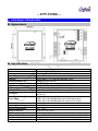
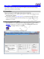
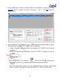
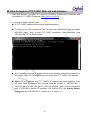
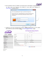
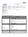
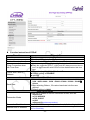
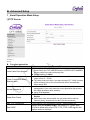
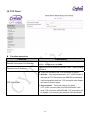
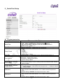
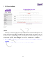
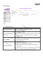
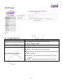
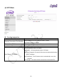
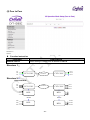
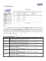
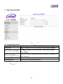
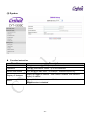
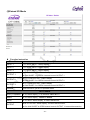
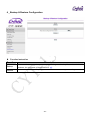
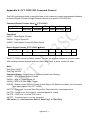
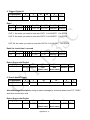
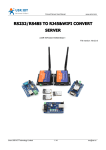
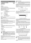
CYT-133SC User Manual Document Version 1.0 Web Version 1.2 2011-03-07 Firmware Version 1.02.00,Mar 8 2011 【Index】 Ⅰ、Hardware Introduction.........................................................................................................1 Ⅱ、Product Overview................................................................................................................3 Ⅲ、WEB Login ..........................................................................................................................4 Ⅳ、Web Function Instruction ..................................................................................................10 One Page Quick Setup .....................................................................................................10 Advanced Setup................................................................................................................13 1、Serial Operation Mode Setup ................................................................................13 (1)TCP Server .......................................................................................................13 (2) TCP Client ........................................................................................................14 (3)UDP ..................................................................................................................15 (4)Extend I/O .........................................................................................................16 2、Serial Port Setup ...................................................................................................17 3、I/O Operation Mode...............................................................................................18 (1)Auto...................................................................................................................18 (2) TCP Server ......................................................................................................20 (3)TCP Client.........................................................................................................21 (4) UDP Mode........................................................................................................22 (5) Peer to Peer .....................................................................................................23 4、I/O State Setup ......................................................................................................24 5、Alert Event E-Mail..................................................................................................25 6、DDNS Setup..........................................................................................................26 (1)TZ0....................................................................................................................26 (2) Dyndns .............................................................................................................27 Management.....................................................................................................................28 1、Device Administration Setting................................................................................28 2、System Status Monitor ..........................................................................................29 3、I/O Status...............................................................................................................30 (1)Non Extend I/O Mode........................................................................................30 (2)Extend I/O Mode ...............................................................................................31 4、Backup & Restore Configuration ...........................................................................32 5、Firmware Upgrade.................................................................................................33 6、PING .....................................................................................................................34 Appendix A- CYT-133SC DIO Command Protocol ..................................................Appendix A-1 Appendix B- Remote reset command..................................................................... Appendix B-1 Appendix C- CGI(URL) command for I/O control ................................................... Appendix C-1 Copyright @ 2011. All Rights Reserved. All trademarks and trade names are the properties of their respective owners. -CYT-133SC- Ⅰ、Hardware Introduction Appearance Specification Item CPU Memory Watchdog Ethernet Communication Port Connectors RS-232 RS-422 RS-485 I/O Control Power Input Operating Temperature Operating Humidity Storage Temperature Surge Protection Electromagnetic protection LED Indicator Weight Dimensions ( L x W x H ) Specification 16 Bits, 100MHZ 256KB Flash & 2MB SDRAM System never halt 10/100 Base-T/Tx/, Automatic MSI/MDI-x port RS232, RS 422, RS 485 DB9(MALE)/RJ-45 TxD, RxD, RTS, CTS, DTR, DSR, DCD,RI,GND Tx+,Tx-, Rx+, Rx-,GND (1200M for the longest distance) Data+, Data-,GND (1200M for the longest distance) 3 Input (short),3 Output – Relay Mode (Maximum Voltage DC30V,1A) Choose one: PWR1: DC9~24V(500MA MAX) 2-pin Separate terminal PWR2: DC9~24V(500MA MAX) DC power to DC socket 0℃ ~ 55℃ 5 ~ 95%RH -20℃ ~ 85℃ Serial port 15KV ESD Ethernet port 1.5KV Power / RXD / TXD / ACT / IN1 / IN2 /IN3 /OUT 1/ OUT2 / OUT3 340g 106.5(86.5 without ear loop)*115(110 without RS232)*28 mm -1- End point -2- Ⅱ、Product Overview CYT-133SC is a RS232/RS485/RS422 converter for the integration of system and Ethernet management, designed and applied to enable traditional industrial serial devices to access data and control devices through Ethernet (intranet or internet) Real time operation system and complete TCP/IP protocol enable CHIYU’s CYT-133SC powerful converter not only providing complete system with highly efficiency but also able to link with network. Easy to install and wire. The Web interface of CYT-133SC is simple, easily to operate, and without operation system limitation. Beside of signal conversion function, CYT-133SC also provides 3 sets of DI and DO to reach the DIO remote control function. Features CYT-133SC support 5 kinds of connection: TCP server, TCP client ,UDP , Real com and Extend I/O ,Users can select suitable connecting way Support DHCP Client, when activate this function, CYT-133SC can get TCP/IP default from DHCP Server when the system activates, Includes IP address, default getaway IP and DNS server. Support PPPoE, PPPoE is an internet protocol for the link simulation of dial-up connection and remote host. Support Dynamic DNS, this enable CYT-133SC connect with dynamic IP by fixed Domain Name, enable hosts situated in different location to get access to CYT-133SC through internet. Auto detecting 10/100 M Ethernet. Enable users to conduct data access or management on CYT-133SC through various operation system of IE , Netscape browser. Allows users to back up and store file system parameter and restore it, for security reasons the backup file will be stored encrypted. The CYT-133SC supports 3 DI/3 DO totally; 3 DI with any combination rule can trigger each DO. By providing a smart and easily setup way via Web, user doesn’t need to have any programmer background. CYT-133SCsupport I/O expansion and can expend to 30 sets of DIO with additional BF-51(DIO BOX). Support Heart Beat function. When CYT-133SC set the Serial Server Mode Setup into UDP, the Heart Beat function will be enabled. Every 30 seconds will send a UDP to server to prove the connection is still enabled. Support Peer to Peer function: Add Peer To Peer function to make the data connection between CYT-133SC. With SMTP client support, you can set system to trigger alarm message via e-mail or SMS (Short Message System) to your mobile phone. Support remote reset command (Command & CGI) and I/O Control CGI command. -3- Ⅲ、WEB Login CYT-133SC contains a HTTP server, thus CYT-133SC can link and connect through Web browser, and then conduct setting. Preparation Before conducting CYT-133SC setting, please assure the following: PC has connected to CYT-133SC, and PC and CYT-133SC are situated in the same WAN with power supplied. If the default IP address (192.168.168.125 ) is occupied by else device, then it is a must to shut down that device first till the setting is over, and then allocate new IP address to CYT-133SC. How to search CYT-133SC 1、After installation of CYT-133SC and network cable is completed, use CYT-133SC’s IP Search to search all CYT-100SC in a certain LAN, or download IP Search tool from CHIYU homepage. Desktop icon as below: 2、Click IP Search icon, will display a window, as shown: -4- 3、While the IP Search window shows up, it will display all CYT-133SC in LAN, and show its Device name, Location, Model Name, IP Address, Subnet Mark, Gateway, Mac Address. Select particular CYT-133SC, then its related information will appear below the window, as shown: 4、The showed information of CYT-133SC can be revised directly in the window, the part can be modified: IP Address, Subnet Mask, Gateway. After modification completed ( MAC Address can not modify ),click Alter then it will display the modified information, as shown: -5- 5、After modification, if want to confirm whether the modification is correct or not, click Refresh button to refresh and check information ( Fig-1 ), click Exit button to leave.(Fig-2) 6、After modification, the IP address of CYT-133SC has matched with its WAN, if want to get access into the Web of CYT-133SC, has two methods: (1)Open IP Search, select and double click particular CTY-133SC, then to enter its webpage. (2)While the internet explorer opened, input CYT-133SC IP address to enter its webpage Remark: WINDOWS XP: 《Step 1》 Click WINDOWS XP my computer , Open Control Pan the left side, please turn to traditional overview and select network link 《Step 2》 on Click LAN, then select content, the link configuration will be shown, click Internet Protocol (TCP/IP) then input the same setting as CYT-133SC, as below figure: -6- WINDOWS 7: 《Step 1》 Click Windows 7 icon, select , open and search for , click Alter Interface Card on the upper-left side. 《Step 2》 Click LAN link, select content, then the LAN settings will be shown, click Internet Protocol(TCP/IPv4), click and input same setting as CYT-133SC, as below figure. -7- How to login to CYT-133SC Web via web browser 1、Start Web browser ( ig: WIN 7 IE ), input CYT-133SC’s IP Address, for example: use the default CYT-133SC IP Address: http://192.168.168.125 2、If connection failed, should check: If CYT-133SC installed and its power supplied properly To examine the LAN connection, can use start toolsExecuteInput cmd open MS-DOS, Input “ ping” to test CYT-133SC connection, input command: ping 192.168.168.125, as shown below: If no response received, it explains the link has troubles either the connection is not proper or the PC’s IP address can not match with CYT-133SC’s IP address Set the PC’s IP address with CYT-133SC’s IP address with same segment, if the PC uses fixed IP address, the address must be ranged in: 192.168.168.1 ~ 192.168.168.65 or 192.168.168.67 ~ 192.168.168.254 , thus it can be compatible with CYT-133SC’s default IP address: 192.168.168.125, the Subnet Mask’s setting must be: 255.255.255.0,please refer to page 6 ~ 7 -8- 3、If the connection with CYT-133SC is successful, then it will display a message window for User name and Password, the default for user name and Password is: admin/admin, as shown below: 4、While the user name and password entered, a Web setting interface of CTY-133SC will be showed, enter it will then display a “ One Page Quick Setup “ page. -9- Ⅳ、Web Function Instruction One Page Quick Setup Function instruction of STATIC IP Function IP Address Subnet mask Gateway Primary DNS Description Set the IP address of the CYT-133SC,default setting is 192.168.168.125 Set the subnet mask of the CYT-133SC,default setting is 255.255.255.0 Set the gateway of the CYT-133SC,default setting is 192.168.168.254 Set the DNS of the CYT-133SC,default setting is 168.95.1.1 Serial Port Mode Baud Rate 1. Set serial port baud rate, the parameters can be selected:1200、 2400、4800、9600、19200、38400、57600、115200、230400 and Others 2. After selecting Others , fill custom baud rate into the user defined 3. Default setting is 19200 Serial Server Mode Connection Mode There are 5 modes to set into connection mode, such as: Real Com TCP SERVER TCP CLIENT UDP Extend I/O(no data conversion) Connection Port Number Set CYT-133SC connection port number, default setting is 50000 Remote Host IP Address 1.Set the remote host IP or domain name,default setting is 0.0.0.0 2.For Client Only - 10 - Function instruction of DHCP CLIENT Function Host Name (optional) Description Fill in the host name , default setting is CHIYU (optional) Serial Port Mode 1.Set serial port baud rate, the parameters can be selected: 1200、2400、4800、9600、19200、38400、57600、115200、230400 and Others Baud Rate 2.After selecting Others , fill custom baud rate into the user defined 3.Default setting is 19200 Serial Server Mode There are 5 modes to set into connection mode, such as: Real Com Connection Mode TCP SERVER TCP CLIENT UDP Extend I/O(no data conversion) Connection Port Number Set CYT-133SC connection port number, default setting is 50000 1.Set the remote host IP or domain name,default setting is 0.0.0.0 Remote Host IP Address 2.For Client Only - 11 - Function instruction of PPPoE Function Description User Name Password Service Name (optional) Fill in the user name, up to 47 characters Fill in the password, up to 35 characters Fill in the service name (optional), up to 47 characters Close Connection when Idle Time Over Default setting is 0 second, the range is from 0 ~ 4294967295 Keep the connection of CYT-133SC and ISP always must set the no into 0 or the connection with PPPoE will be disabled when Idle time over. PPPoE with Fixed IP Address Baud Rate Connection Mode After selecting ENABLE , fill in fixed IP Default setting is DISABLE optional Serial Port Mode 1.Set serial port baud rate, the parameters can be set:1200、 2400、4800、9600、19200、38400、57600、115200、230400及 Others 2.After selecting Others , fill custom baud rate into the user defined 3.Default setting is 19200 Serial Server Mode There are 5 modes to set into connection mode, such as: Real Com TCP SERVER TCP CLIENT UDP Extend I/O(no data conversion) Connection Port Number Set CYT-133SC connection port number, default setting is 50000 Remote Host IP Address 1.Set the remote host IP or domain name,default setting is 0.0.0.0 2.For Client Only - 12 - Advanced Setup 1、Serial Operation Mode Setup (1)TCP Server Function instruction Function Local Listen Port Number Close Connection When Remote Idle Access Password Keep Alive Check Max TCP Connection Real COM Description If data transmit thru TCP/IP remote command, must select Serial Server Mode into TCP SERVER and set LISTEN PORT NUMBER into the same value with monitoring side. Default setting is 50000 The default setting of close connection time is 100 seconds and the range is from 0 ~ 32768 The value must set to be 0 if you want to keep CYT-133SC connect with monitoring side or the connection will be off automatically when remote idle. Make sure the data secure, user must set the code for management. User must inset the correct password and process the further procedure after authority. up to 31 characters Set Enable or Disable keep alive check function,default setting is Disable While keep alive check enable, the pin packet will be send to Gateway every 30 seconds to make cure the connection. The maximum TCP connection is 4 sets , default setting is 1 When using the Virtual COM, if you need CYT-133SC with VCOM to send each other RTS / CTS, DTR / DSR signal, this option must be checked - 13 - (2) TCP Client Function instruction Function Remote Connection Port Number Remote Host IP Address Description Set the remote connection port number,the range is 0 ~ 65535,default setting is 50000 Set remote host IP address or domain name,default setting is 0.0.0.0 There are 2 modes to set TCP connection to server: 1.Start Up:This mode means when CYT-133SC enable, it will build the TCP connection with SERVER immediately. It will automatically build the TCP connection after disable TCP Connection and then re-connect again. 2.Any Character:This mode means only when CYT-133SC receives data from RS232/422/485, it will build TCP connection with SERVER. TCP connection will be disable if not receiving the data from RS232/422/485. - 14 - (3)UDP Function instruction Function Description Set the remote connection port number,the range is 0 ~ Remote Connection Port Number 65535,default setting is 50000 Set remote host IP address or domain name,default setting is Remote Host IP Address Local Listen Port 0.0.0.0 Set the local listen port,default setting is 50000 How many seconds to transmit a UDP heart beat to server can be selected. It’s helpful to know the connection with Heart Beat SERVER enabled. Default setting is Disabled, and the maximum setting is 65535 seconds. - 15 - (4)Extend I/O When set CYT-133SC into Extend I/O mode, it won’t have the data conversion function. It can expend I/O by connect with BF-51. Structure: CTY-133SC RS485 BF51 TID 1 IN 4 to 6 OUT 4 to 6 BF51 TID 2 IN 7 to 9 OUT 7 to 9 BF51 TID 9 IN 28 to 30 OUT 28 to 30 Master IN 1 to 3 OUT 1 to 3 PS:BF-51 is the I/O box with 3 sets of DI / DO. TID set by DIP switch and maximum can connect with BF-51 * 9. - 16 - 2、Serial Port Setup Function instruction Function Baud Rate Data Bits Parity Check Stop Bits Flow Control Force Packet Transmit Time (10ms) Force Packet Transmit Length (bytes) Delimiter 1 Delimiter 2 Description 1.Set serial port baud rate, the parameters can be selected:1200、2400、4800、 9600、19200、38400、57600、115200、230400及Others 2.After selecting Others , fill custom baud rate into the user defined 3.Default setting is 19200 Set the data bits, 5,6,7,8 parameters can be selected, default setting is 8 Set the parity check,4 parameters can be selected: 1.odd 2.Even 3.Mark 4.Space Default setting is None Set the stop bits, 1,2 parameters can be selected, default setting is 1 Set the flow control,2 parameters can be selected: Xon/Xoff:Software flow control CTS/RTS:Hardware flow control Default setting is None Force packet transmit time The minimum setting is 10ms of setting serial interval between data. Default setting is 20ms. Force packet transmit length. The serial set length of data transmission range is from 1 ~ 1500bytes. Default setting is 1000 Set the transmission data end by identified delimiter and if your transmission data includes the identified delimiter, CYT-133SC will send out packet at once. Default setting is disabled. The range is from 0x00 ~ 0xFF Set the transmission data end by identified delimiter and if your transmission data includes the identified delimiter, CYT-133SC will send out packet at once. Default setting is disabled. The range is from 0x00 ~ 0xFF - 17 - 3、I/O Operation Mode (1)Auto This page provides smart I/O control. No need to have any programming background, only set the connection of each I/O via this page, and can make the linked connection of each I/O. For instance, there are 2 devices to connect with IN1 /IN2 and OUTPUT1. The trigger mode is IN1/IN2 trigger OUTPUT1 at the same time. The OUTPUT1 configuration is IN1 and IN2. Through alarm output setting, it can send alarm mail to user when OUTPUT 1~3 has been triggered. When select AUTO mode, command mode connection will be disabled. - 18 - Function instruction Function Description Triggered Rule Set trigger OUTPUT 1 condition, use IN1~3 ,AND and OR these conditions to set. For instance: When IN1、IN2 and IN3 enable at the same time, meanwhile OUTPUT1 will OUTPUT 1 be triggered. The setting condition must be IN1 AND IN2 AND IN3. Alarm Generation Enable or disable alarm output function, the default setting is Enable. When OUTPUT1 has been triggered, alarm mail will send to user automatically. Triggered Rule Set trigger OUTPUT 2 condition, use IN1~3 ,AND and OR these conditions to set. For instance: When IN1、IN2 and IN3 enable at the same time, meanwhile OUTPUT1 will OUTPUT 2 be triggered. The setting condition must be IN1 AND IN2 AND IN3. Alarm Generation Enable or disable alarm output function, the default setting is Enable. When OUTPUT2 has been triggered, alarm mail will send to user automatically. Triggered Rule Set trigger OUTPUT 3 condition, use IN1~3 ,AND and OR these conditions to set. For instance: When IN1、IN2 and IN3 enable at the same time, meanwhile OUTPUT1 will OUTPUT 3 be triggered. The setting condition must be IN1 AND IN2 AND IN3. Alarm Generation Enable or disable alarm output function, the default setting is Enable. When OUTPUT3 has been triggered, alarm mail will send to user automatically. - 19 - (2) TCP Server Function instruction Function Local Listen Port Number Close Connection When Remote Idle Access Password Description Set local I/O port, the range is from0 ~ 65535. Default setting is 50001 The default setting of close connection time is 10 seconds and the range is from 0 ~ 32768 The value must set to be 0 if you want to keep CYT-133SC connect with monitoring side or the connection will be off automatically when remote idle. Make sure the data secure, user must set the code for management. User must inset the correct password and process the further procedure after authority. up to 31 characters Automatically return I/O status Disable:No automatically return I/O Status Auto Report I/O Status State Changed:I/O status will be returned automatically when INPUT changes. Periodically:Set I/O status return automatically every few seconds. Through:I/O status will be returned thru Serial and ETH. - 20 - (3)TCP Client Function instruction Function Remote Connection Port Number Remote Host IP Address Description Set local I/O port, the range is from0 ~ 65535. Default setting is 50001 Default setting of remote host IP address is 0.0.0.0 Automatically return I/O status Disable:No automatically return I/O Status State Changed:I/O status will be returned automatically when Auto Report I/O Status INPUT changes. Periodically:Set I/O status return automatically every few seconds. Through:I/O status will be returned thru Serial and ETH. - 21 - (4) UDP Mode Function instruction Function Remote Connection Port Number Description Set local I/O port, the range is from0 ~ 65535. Default setting is 50001 Remote Host IP Address Default setting of remote host IP address is 0.0.0.0 Local Listen Port Default setting of local I/O port is 50001 Automatically return I/O status Disable:No automatically return I/O Status State Changed:I/O status will be returned automatically when Auto Report I/O Status INPUT changes. Periodically:Set I/O status return automatically every few seconds. Through:I/O status will be returned thru Serial and ETH. - 22 - (5) Peer to Peer Function instruction Function Remote Peer IP Description Default setting of remote peer IP address is 0.0.0.0. Structure 1: IN1 IN2 IN3 OUT1 CYT-133SC LAN/WAN CYT-133SC LAN/WAN CYT-133SC OUT2 OUT3 Structure 2: Extend I/O Mode IN1 IN2 IN3 OUT1 CYT-133SC BF51 BF51 RS485 RS485 OUT28 IN28 IN29 IN30 OUT2 OUT3 BF51 BF51 - 23 - OUT29 OUT30 4、I/O State Setup This page is for I/O operation setting when selecting I/O Operation Mode Setup (Auto). According to the INOUT signal changes can control OUTPUT external driver device. You can insert device name in Device Description for identification. You can also set up OUTPUT Latch Time for output time length. If the setting is 0 then OPTPUT can only be removed when INPUT status back to normal. Function instruction Function INPUT 1 INPUT 2 INPUT 3 OUTPUT 1 OUTPUT 2 OUTPUT 3 Description INPUT 1 status can set OPEN or SHORT, default setting is OPEN. Can set device name in Device Description for identification, up to 23 characters. STATUS:Set Enable or Disable INPUT1 detection INPUT 2 status can set OPEN or SHORT, default setting is OPEN. Can set device name in Device Description for identification, up to 23 characters. STATUS:Set Enable or Disable INPUT2 detection INPUT 3 status can set OPEN or SHORT, default setting is OPEN. Can set device name in Device Description for identification, up to 23 characters. STATUS:Set Enable or Disable INPUT3 detection OUTPUT 1 setting, when INPUT signal changes can set OUTPUT into OPEN or SHORT, default setting is SHORT. Can set device name in Device Description for identification, up to 23 characters. Set OUTPUT 1 duration, default setting is 0. OUTPUT 2 setting, when INPUT signal changes can set OUTPUT into OPEN or SHORT, default setting is SHORT. Can set device name in Device Description for identification, up to 23 characters. Set OUTPUT 2 duration, default setting is 0. OUTPUT 3 setting, when INPUT signal changes can set OUTPUT into OPEN or SHORT, default setting is SHORT. Can set device name in Device Description for identification, up to 23 characters. Set OUTPUT 3 duration, default setting is 0. - 24 - 5、Alert Event E-Mail Function instruction Function E-mail Alert Domain Name (optional) SMTP Mail Server Description Enable or Disable event alert mail setting, default setting is Disable. Domain name setting up to 59 characters, default setting is blank. (Non-required) SMTP server setting, take msa.hinet.net for instance, the setting is up to 47 characters. E-mail Alerts To Receiver mail setting up to 47 characters. Return Address Sender mail setting up to 47 characters. - 25 - 6、DDNS Setup (1)TZ0 Function instruction Function Description E-mail Address Fill in the E-mail address for DDNS , up to 47 characters Password key Fill in the password key for DDNS,up to 31 characters Device DNS Name Fill in the device DNS name,for example:hostname.tzo.com Display the registry IP address,when DDNS is enabled, It will show the Registry IP Address registry IP address Display DNS Serve status,when DDNS server does not enable ,it will show Status “DDNS function is disabled” - 26 - (2) Dyndns Function instruction Function Description Username Fill in the username for DDNS,up to 31 characters Password Fill in the password for DDNS,up to 31 characters Device DNS Name Fill in the device DNS name,for example:hostname.dyndns.org Display the registry IP address,when DDNS is enabled, It will show the Registry IP Address registry IP address Display DNS Serve status,when DDNS server does not enable ,it will show Status “DDNS function is disabled” - 27 - Management 1、Device Administration Setting Function instruction Function Description Select unblock or block standard http port,default setting is Block Standard Http Port(80) Management UNBLOCK(80) If other port sequence has to be set, select BLOCK, and then fill in the port sequence. Device Management IP Address Device Hostname Device Location Display and set the device management IP address , default setting is 192.168.200.200 Fill in the device hostname, default setting is CHIYU Fill in the device location , default setting is blank User Name:Fill in the user name Administrator Password Password Change:Change the password, for security reasons, please fill in a new password to replace the default management Password Confirm:Confirm the new password Block Ping Request Select unblock or block ping request function , default setting is unblock MAC Address Change If you want to change the MAC address, fill in the new MAC address Reset System to Factory Default Reboot System Execute this function will reset system to factory default Execute this function will reboot system - 28 - 2、System Status Monitor Function instruction Function Product Name Firmware Version System Up Time IP Configuration Mode Operation Mode Connection Port I/O Operation Mode I/O Connection Port MAC Address IP Address Subnet mask: Default Gateway Primary DNS: STATUS Force Packet Time/Length: Baud Rate Data Bits Parity Check Stop Bits: Flow Control: Ethernet Serial Description Display the product name:CYT-133SC Display the firmware version:1.02.00,Mar 8 2011 Display system up time,the sequence is hour/minute/second Display the IP configuration,default setting is STATIC IP Display the operation mode,default setting is TCP SERVER Display the connection port,default setting is 50000 Display the I/O operation mode,default setting is AUTO Display the I/O connection port,default setting is blank Display the MAC address of CYT-133SC Display CYT-133SC address, default setting is 192.168.168.125 Display CYT-133SC Subnet mask, default setting is 255.255.255.0 Display CYT-133SC Default Gateway, default setting is 192.168.168.254 Display CYT-133SC Primary DNS address, default setting is 168.95.1.1 Display CYT-133SC internet status Display Force Packet Time/Length, default setting is 20ms/1000bytes Display Baud Rate, default setting is 19200 Display Data Bits, default setting is 8 Display Parity Check, default setting is None Display Stop Bits, default setting is 1 Display Flow Control, default setting is None RX & TX display the total data amount of data receive and transmission of Ethernet. RX & TX display the total data amount of data receive and transmission of Serials. - 29 - 3、I/O Status (1)Non Extend I/O Mode Function instruction Function Description INPUT 1 CYT-133SC INPUT 1 status display INPUT 2 CYT-133SC INPUT 2 status display INPUT 3 CYT-133SC INPUT 3 status display OUTPUT 1 OUTPUT 2 OUTPUT 3 Refresh CYT-133SCOUTPUT 1 status display Click SHORT-1 or OPEN-1 manual control OUTPUT 1 CYT-133SCOUTPUT 2 status display Click SHORT-2 or OPEN-2 manual control OUTPUT 2 CYT-133SCOUTPUT 3 status display Click SHORT-3 or OPEN-3 manual control OUTPUT 3 Click Refresh to get the I/O updated status. - 30 - (2)Extend I/O Mode Function instruction Function Description INPUT 1 CYT-133SC INPUT 1 status display INPUT 2 CYT-133SC INPUT 2 status display INPUT 3 CYT-133SC INPUT 3 status display OUTPUT 1 OUTPUT 2 OUTPUT 3 Refresh CYT-133SC OUTPUT 1 status display Click SHORT-1 or OPEN-1 manual control OUTPUT 1 CYT-133SCOUTPUT 2 status display Click SHORT-2 or OPEN-2 manual control OUTPUT 2 CYT-133SCOUTPUT 3 status display Click SHORT-3 or OPEN-3 manual control OUTPUT 3 Click Refresh to get the I/O updated status. BF-51 status BF51(1~9)Status BF-51 status display, (1~9) indicates TID of BF-51. Status BF-51 status display,Online or Offline INPUT BF-51 INPUT status display, X means disconnect. OUTPUT BF-51 OUTPUT status display, X means disconnection. Can click SHORT or OPEN manual control OUTPUT, X means disconnection. - 31 - 4、Backup & Restore Configuration Function instruction Function Description After execution, can save the present system settings as a backup file, and save it in Backup Restore hardware, the sub-name of the saved file is .cfg Browse and select saved file( .cfg ), execute Restore to restore system settings - 32 - 5、Firmware Upgrade Function instruction Function Description Browse and select firmware, execute Upgrade to upgrade firmware Please select a file to upgrade Has to assure the possibility of power supply during the process of upgrading, or severe damage will be caused. What if upgrade different firmware to different products, and it will also cause severe damage. - 33 - 6、PING Function instruction Function Description Source IP Address Display CYT-133SC IP address Destination IP Address Input IP address of Remote Host Packet Number Set up the number of PING package, ranged 1 ~4 , the default 4 Ping Size Set up the size of PING package, the utmost setting 1460 bytes. Ping Result Display Sent Request data Display Receive Reply data - 34 - Appendix A- CYT-133SC DIO Command Protocol This DIO command protocol is described here to let customer’s remote management software to access Digital I/O state through Ethernet network by a specific TCP/UDP port. Command Packet Format: (Host CYT-133SC) Length(Bytes) 2 2 32 32 2 1 Start Flag Command Data1 Data2 End Flag CRC Command: 0x0001 - Read Digital I/O state 0x0003 - Trigger Digital I/O 0x0005 - Auto Report Current I/O State Packet Return Packet Format: (CYT-133SC Host) Length(Bytes) 2 2 32 32 2 1 Start Flag Command Status Data1 Data2 End Flag CRC The CYT-133SC returns by Return packet. You can get command status to know the result after sending command packet and from Data1 and Data2 to know current I/O state. Note: Start Flag: 0xF0F0 End Flag: 0xF0F0 Command Status: the definition of command code is as following 0x0002 – ACK of Read Digital I/O state 0x0004 – ACK of Trigger Digital I/O 0x0006 – ACK of E-mail Alarm Trigger 0x0010 – Report current Digital I/O state (If Auto Report I/O Status is enabled, you will receive this report packet from CYT-133SC) 0xFFFC – Flag error, incorrect Start Flag or End Flag received in command packet 0xFFFD – Length error, the length of command packet is invalid 0xFFFE – CRC error, incorrect CRC value 0xFFFF – Command error, no such command CRC value = 0 – total sum from field of ‘Start Flag” to “End Flag” Appendix A - 1 - The format of each command code is as following: 1. Read Digital I/O state Length(Bytes) 2 2 0xF0F0 0x0001 32 32 2 Xxx Xxx 0xF0F0 CRC (don’t care) (don’t care) Return Successful Packet Length(Bytes) 2 2 32 32 2 1 0xF0F0 0x0002 Data1 Data2 0xF0F0 CRC Data1 Data[0] Data[1] IN-1 IN-2 Data[28] IN-29 Data[29] Data[30] IN-30 Data[31] reserved reserved …… IN-1: state of IN1, 0 for SHORT, 1 for OPEN, 2 for Deactivated IN-2: state of IN2, 0 for SHORT, 1 for OPEN, 2 for Deactivated IN-30: state of IN30, 0 for SHORT, 1 for OPEN, 2 for Deactivated Data2 Data[0] Data[1] OUT-1 OUT-2 1 Data[28] Data[29] Data[30] OUT-29 OUT-30 Data[31] reserved reserved …… OUT-1: state of OUT1, 0 for SHORT, 1 for OPEN, 2 for Deactivated OUT-2: state of OUT2, 0 for SHORT, 1 for OPEN, 2 for Deactivated OUT-30: state of OUT30, 0 for SHORT, 1 for OPEN, 2 for Deactivated Appendix A - 2 - 2. Trigger Digital I/O Length(Bytes) 2 2 32 32 2 1 0xF0F0 0x0003 Data1 Data2 0xF0F0 CRC Data1 Data[0] Data[1] OUT-1 Data[28] OUT-2 Data[29] OUT-29 OUT-30 Data[30] Data[31] reserved reserved …… OUT-1: the value you want to write into OUT1, 0 for SHORT, 1 for OPEN OUT-2: the value you want to write into OUT2, 0 for SHORT, 1 for OPEN OUT-30: the value you want to write into OUT30, 0 for SHORT, 1 for OPEN Data2 for Latch time in second Data[0] Data[1] LT-1 Data[28] LT-2 LT-29 Data[29] Data[30] Data[31] LT-30 reserved reserved Return Successful Packet Length(Bytes) 2 2 0xF0F0 0x0004 32 32 2 1 Xxx Xxx 0xF0F0 CRC (don’t care) (don’t care) 3. E-mail Alarm Trigger Length(Bytes) 2 2 32 32 2 1 0xF0F0 0x0005 Alarm Message Description 0xF0F0 CRC Alarm Message Description: string of alarm message by customer attach and CYT-133SC send this content by e-mail Return Successful Packet Length(Bytes) 2 2 0xF0F0 0x0006 32 32 2 1 Xxx Xxx 0xF0F0 CRC (don’t care) (don’t care) Appendix A - 3 - 4. Auto Report Current I/O State Packet (CYT-133SC to Host) Length(Bytes) 2 2 32 32 2 1 0xF0F0 0x0010 Data1 Data2 0xF0F0 CRC Data1 Data[0] Data[1] Data[2] Data[3] Data[30] IN-1 reserved reserved IN-2 IN-3 IN4 Data[31] IN-1: state of IN1, 0 for SHORT, 1 for OPEN, 2 for Deactivated IN-2: state of IN2, 0 for SHORT, 1 for OPEN, 2 for Deactivated IN-3: state of IN3, 0 for SHORT, 1 for OPEN, 2 for Deactivated Data2 Data[0] Data[1] Data[2] Data[3] Data[30] OUT-1 reserved reserved OUT-2 OUT-3 reserved Data[31] OUT-1: state of OUT1, 0 for SHORT, 1 for OPEN OUT-2: state of OUT2, 0 for SHORT, 1 for OPEN OUT-3: state of OUT3, 0 for SHORT, 1 for OPEN 5. Keep Alive (Only useful when CYT-133SC’s I/O mode is acting as TCP Client) : (CYT-133SC Host) Length(Bytes) 2 2 64 2 1 0xF0F0 0x0007 RESV 0xF0F0 CRC 0x0007 – Keep Alive (new created) Return Successful Packet (Host CYT-133SC) Length(Bytes) 2 2 0xF0F0 0x0008 32 32 2 1 Xxx Xxx 0xF0F0 CRC (don’t care) (don’t care) 0x0008 – ACK of Keep Alive (New created) Appendix A - 4 - Appendix B- Remote reset command a. CGI (URL) command http://192.168.1.125/reboot.htm@admin:admin b. CHIYU proprietary command, UDP connection/port 5050 Byte SNG 16 CMD 4 SNG (16 bytes): signature data, should be “CHIYU Reboot CMD” case sensitive. CMD (4 bytes): 0x00 00 00 20 Return packet: Byte SNG 16 ACK 4 SNG (16 bytes): signature data, should be “CHIYU Reboot CMD” case sensitive. ACK(4 bytes): 0x00 00 00 21 Appendix B - 1 - Appendix C- CGI(URL) command for I/O control Get I/O Status : http://192.168.3.125/iostatus.htm@admin:admin Username Password Energize Output Relay command: For example : Energize Relay No.1 all the time http://192.168.3.125/set_relay.php&no=1&time=0@admin:admin Energize Relay No.2 and latch 10 seconds http://192.168.3.125/set_relay.php&no=2&time=10@admin:admin Clear Output Relay command: For example : Clear Relay No.1 http://192.168.3.125/clear_relay.php&no=1@admin:admin Clear Relay No.2 http://192.168.3.125/clear_relay.php&no=2@admin:admin Appendix C - 1 -