1
VoIP ATA NVP-300 SERIES
USER’S MANUAL
VoIP ATA NVP-300 SERIES USER’S MANUAL Ver.A6
Copyright
Copyright © 2011 by National Enhance Technology Corp. All rights reserved.
Trademarks
NETSYS is a trademark of National Enhance Technology Corp.
Other brand and product names are registered trademarks or trademarks of their respective holders.
Legal Disclaimer
The information given in this document shall in no event be regarded as a guarantee of conditions or characteristics. With respect
to any examples or hints given herein, any typical values stated herein and/or any information regarding the application of the
device, National Enhance Technology Corp. hereby disclaims any and all warranties and liabilities of any kind, including without
limitation warranties of non-infringement of intellectual property rights of any third party.
Statement of Conditions
In the interest of improving internal design, operational function, and/or reliability, NETSYS reserves the right to make changes to the
products described in this document without notice. NETSYS does not assume any liability that may occur due to the use or
application of the product(s) or circuit layout(s) described herein.
Maximum signal rate derived from IEEE Standard specifications. Actual data throughput will vary. Network conditions and
environmental factors, including volume of network traffic, building materials and construction, and network overhead lower actual
data throughput rate.
1
VoIP ATA NVP-300 SERIES USER’S MANUAL Ver.A6
Safety Warnings
For your safety, be sure to read and follow all warning notices and instructions before using the device.
DO NOT open the device or unit. Opening or removing covers can expose you to dangerous high voltage points or other
risks. ONLY qualified service personnel can service the device. Please contact your vendor for further information.
Use ONLY the dedicated power supply for your device. Connect the power cord or power adapter to the right supply
voltage (110V AC in North America or 230V AC in Europe).
DO NOT use the device if the power supply is damaged as it might cause electrocution. If the power supply is damaged,
remove it from the power outlet. DO NOT attempt to repair the power supply. Contact your local vendor to order a new
power supply.
Place connecting cables carefully so that no one will step on them or stumble over them. DO NOT allow anything to rest
on the power cord and do not locate the product where anyone can work on the power cord.
DO NOT install nor use your device during a thunderstorm. There may be a remote risk of electric shock from lightning.
DO NOT expose your device to dampness, dust or corrosive liquids.
DO NOT use this product near water, for example, in a wet basement or near a swimming pool.
Connect ONLY suitable accessories to the device. Make sure to connect the cables to the correct ports.
DO NOT obstruct the device ventilation slots, as insufficient airflow may harm your device.
DO NOT place items on the device.
DO NOT use the device outside, and make sure all the connections are indoors. There may be a remote risk of electric
shock from lightning.
Be careful when unplugging the power, because the transformer may be very hot.
Keep the device and all its parts and accessories out of children’s reach.
Clean the device using a soft and dry cloth rather than liquid or atomizers. Power off the equipment before cleansing it.
This product is recyclable. Dispose of it properly.
2
VoIP ATA NVP-300 SERIES USER’S MANUAL Ver.A6
Foreword
NVP-300 series allows you to make telephone calls using a computer network, over a data network like the Internet. NVP-300
series converts the voice signal from your telephone into a digital signal that travels over the internet then converts it back at
the other end so you can speak to anyone with a regular phone number. When placing a VoIP call using a phone with an
adapter, you'll hear a dial tone and dial just as you always have. Some gateways at the recipient side can convert phonecall
back into voice signal, you need go through a VOIP to PBX gateway if you'd like the phone call from VOIP to regular phone
number.
VOIP Solution
Internet Voice, also known as Voice over Internet Protocol (VoIP), is a technology that allows you to make telephone calls using
a broadband Internet connection instead of a regular (or analog) phone line. Some services using VoIP may only allow you to
call other people using the same service, but others may allow you to call anyone who has a telephone number - including local,
long distance, mobile, and international numbers. Also, while some services only work over your computer or a special VoIP
phone, other services allow you to use a traditional phone through an adaptor.
3
VoIP ATA NVP-300 SERIES USER’S MANUAL Ver.A6
Basic Services
What is Proxy Servers?
Proxy servers handle two functions:
1. Accept registrations from the SIP user agents,
2. Proxy requests and responses between user agents.
Registration is the process by which a user agent tells the proxy who it is and at what IP address and port that it can be reached via
SIP. Registration usually expires within a finite period (e.g., 60s or 3600s) and the UA shall renew their registration periodically
before the last registration expires. When a user agent initiates a call, it sends a SIP INVITE request to the proxy server and
indicates the target recipient of the call. The proxy server then consults a database to determine where to forward the request to the
destination user agent. The proxy server can request authentication credentials from the user agent before granting the service.
The credentials are computed by the user agent based on a pre-provisioned password and a challenge “nonce” dynamically
generated by the proxy server per request. This mechanism prevents unauthorized user agents from getting IP Telephony services
through the proxy server. SIP proxy servers are operated by the IP Telephony service provider and resides at the service provider’s
domain. They may be implemented in many different ways. They can be stateless, stateful, or B2BUA. Stateless proxies do not
maintain states of each call; they simply proxy the requests and responses between the user agents. Hence they are the simplest,
most scalable, but provide the least types of services. Advanced IP Telephony services are possible with these proxies only with
intelligent user agent devices that are capable of delivering these services without proxy intervention. Stateful proxies maintain the
call state of each call and can provide more intelligent services at the expense of more processing load per call. B2BUA proxies
process every request and response from the user agents and are capable of providing very advance services even with relatively
simple user agent devices. Obviously B2BUA proxies have the highest processing load per call.
4
VoIP ATA NVP-300 SERIES USER’S MANUAL Ver.A6
What is SIP Services?
Today’s PSTN offers a large number of enhanced services in addition to basic phone services. Most of the services offered by the
PSTN are accessed by the subscribers through their telephone sets. The subscribers provide their input by talking into the handset,
pressing the keypad, the switch hook or flash button, while the PSTN presents instructions/information/confirmation to the
subscribers through a variety of audio tones, beeps and/or announcements. The PHONE ADAPTER supports a comparable range of
services via a similar user interface in order to make the IP Telephony service transparent to subscribers.
The PHONE ADAPTER is fully programmable and can be custom provisioned to emulate just about any traditional telephony service
available today. This ability to transparently deliver legacy services over an IP network coupled with the availability of Internet
connected devices (PCs. PDA, etc.) and browsers opens up a new world of potential offerings that a provider can use to differentiate
their service and grow their business.
Enhanced Services
Enhanced Services are provided in addition to Basic calling services and accessed by way of a touchtone phone through a series of
menus. Since the service enabled by the NVP-300 series are Internet in nature, these enhanced services can be made better by
offering users a web browser based interface to control certain aspects of some or all services.
Caller ID
In between ringing bursts, the NVP-300 series can generate a Caller ID signal to the attached phone when the phone is on-hook.
Calling Line Identification Presentation (CLIP) Some subscribers will elect to always block their Caller ID information, yet there may
be a circumstance where sending Caller ID information for a particular call is desired, i.e. trying to reach a party that does not accept
Caller ID blocked calls. The subscriber activates this service to send his Caller ID when making an outgoing call. To activate the
service, the subscriber enters the corresponding * or # code prior to making the call. This service is in effect only for the duration of
the current call. Calling Line Identification Restriction (CLIR) – Caller ID Blocking.
The subscriber activates this service to hide his Caller ID when making an outgoing call. To activate the service, the subscriber
5
VoIP ATA NVP-300 SERIES USER’S MANUAL Ver.A6
enters the corresponding * or # code prior to making the call. This service is in effect only for the duration of the current call.
Call Waiting
The subscriber can accept a call from a 3rd party while engaging in an active call. The NVP-300 series shall alert the subscriber for
the 2nd incoming call by playing a call waiting tone.
Disable or Cancel Call Waiting By setting the corresponding configuration parameter on the NVP-300 series, the PHONE ADAPTER
supports disabling of call waiting permanently or on a per call basis.
Call-Waiting with Caller ID in between call waiting tone bursts, the NVP-300 series can generate a Caller-ID signal to the attached
phone when it is off hook.
Call Transfer
Three parties are involved in Call Transfer: The transferor, transferee, and transfer target. There are 2 flavors of call transfer:
Attended Transfer (Transfer with consultation) and Unattended Transfer (“Blind” Transfer).
Attendant Transfer the transferor dials the number of the transfer target, then he hangs up (or enters some * or # code) when the
transfer target answers or rings to complete the transfer.
Unattended or “Blind” Transfer
The transferor enters some * or # code and then dials the number of the transfer target to complete the transfer (without waiting for
the target to ring or answer).
Call Hold
Call Hold lets you put a caller on hold for an unlimited period of time. It is especially useful on phones without the hold button. Unlike
a hold button, this feature provides access to a dial tone while the call is being held.
6
VoIP ATA NVP-300 SERIES USER’S MANUAL Ver.A6
Three-Way Calling
The subscriber can originate a call to a 3rd party while engaging in an active call.
Three-Way Ad-Hoc Conference Calling
The NVP-300 series can host a 3-way conference and perform 3-way audio mixing.
Call Forwarding
These services forward all the incoming calls to a static or dynamically configured destination number based on three different
settings. These services may be offered by the NVP-300 series or by the SIP proxy server. They can be activated by entering certain
* or # code, followed by entering a telephone number to forward calls to. The NVP-300 series provides audio instructions to prompt
the user for a forwarding number and confirms that the requested service has been activated.
Speed Dial Phone
The NVP-300 series supports user programming of up to ten phone number, local,international or emergency numbers and/or IP
addresses for fast and easy access.
IVR (Interactive Voice Response)
Provides mechanism for information to be stored and retrieved using voice and a touchtone telephone.
Auto provisioning
Provisioning servers are used to provision the subscriber user agent devices,e.g. the NVP-300 series. When a subscriber signs up
for IP Telephony service, he selects an appropriate service level and enters his personal information including billing information.
This information is processed by the provisioning server and stored into the service provider’s customer
database. The provisioning server generates a device profile based on the subscriber’s choice of options. The device profile, which
is list of configuration parameters, is downloaded into the NVP-300 series from the provisioning server. The NVP-300 series can be
configured to contact the provisioning server periodically to check for any update of the device profile, which may include a firmware
7
VoIP ATA NVP-300 SERIES USER’S MANUAL Ver.A6
upgrade or configuration modification to the NVP-300 series.(For detailed information please reference to P.57)
Auto Answer(NVP-300SO/SSO only)
Auto Answer will auto change from FXS to FXO(PBX) when call in without reply over setting time. Call in persons can call you again
through FXO when NVP-300 series auto change to FXO and hearing a dial tone.
8
VoIP ATA NVP-300 SERIES USER’S MANUAL Ver.A6
CONTENT
COPYRIGHT ........................................................................................................................................................ 1
SAFETY WARNINGS ........................................................................................................................................... 2
FOREWORD ........................................................................................................................................................ 2
CHAPTER 1. UNPACKING INFORMATION......................................................................................................... 2
1.1 Check List .....................................................................................................................................................................................2
CHAPTER 2. INSTALLATION .............................................................................................................................. 2
2.1 Hardware Installation ...................................................................................................................................................................2
2.2 Pre-installation Requirements.....................................................................................................................................................2
2.3 General Rules ...............................................................................................................................................................................2
2.4 Connecting the NVP-300 series ..................................................................................................................................................2
CHAPTER 3. HARDWARE DESCRIPTION ......................................................................................................... 2
3.1 Front Panel....................................................................................................................................................................................2
3.2 Front Indicators ............................................................................................................................................................................2
3.3 Rear Panel.....................................................................................................................................................................................2
9
VoIP ATA NVP-300 SERIES USER’S MANUAL Ver.A6
CHAPTER 4. INTRODUCTION ............................................................................................................................ 2
4.1 Hardware Overview ......................................................................................................................................................................2
4.2 Software Overview .......................................................................................................................................................................2
CHAPTER 5. IVR INTERFACE FOR THE NVP-300 SERIES............................................................................... 2
CHAPTER 6. SETUP THE NVP-300 SERIES BY WEB BROWSER.................................................................... 2
6.1 Login. ............................................................................................................................................................................................2
6.2 System Information for the NVP-300 series. ..............................................................................................................................2
6.3 Phone Book ..................................................................................................................................................................................2
6.4.1 Call Forward function: ............................................................................................................................................................................2
6.4.2 SNTP Setting function: ...........................................................................................................................................................................2
6.4.3 Volume Setting function: ........................................................................................................................................................................2
6.4.4 Block Setting function:...........................................................................................................................................................................2
6.4.5 Caller ID function: ...................................................................................................................................................................................2
6.4.6 Auto Dial Setting function: .....................................................................................................................................................................2
6.4.7 Flash Time Setting function: ..................................................................................................................................................................2
6.4.8 Call Waiting Setting function: ................................................................................................................................................................2
6.4.9 T.38 Setting function:..............................................................................................................................................................................2
6.5 Network .........................................................................................................................................................................................2
6.5.1 Network Status:.......................................................................................................................................................................................2
6.5.2 WAN Settings: .........................................................................................................................................................................................2
6.5.3 LAN Settings: ..........................................................................................................................................................................................2
6.5.4 Network Settings: ...................................................................................................................................................................................2
6.5.5 DDNS Setting: .........................................................................................................................................................................................2
6.5.6 VLAN Setting:..........................................................................................................................................................................................2
10
VoIP ATA NVP-300 SERIES USER’S MANUAL Ver.A6
6.6 SIP Settings ..................................................................................................................................................................................2
6.6.1 Port Settings: ..........................................................................................................................................................................................2
6.6.2 Codec Settings:.......................................................................................................................................................................................2
6.6.3 Codec ID Setting: ....................................................................................................................................................................................2
6.6.4 RTP Setting: ............................................................................................................................................................................................2
6.6.5 DTMF Setting:..........................................................................................................................................................................................2
6.6.6 RPort Function:.......................................................................................................................................................................................2
6.6.7 Other Settings: ........................................................................................................................................................................................2
6.7 NAT Trans......................................................................................................................................................................................2
6.8 Others............................................................................................................................................................................................2
6.9 System Auth. ................................................................................................................................................................................2
6.10 Save Change...............................................................................................................................................................................2
6.11 Update .........................................................................................................................................................................................2
6.12 Reboot.........................................................................................................................................................................................2
6.13 Auto Answer(NVP-300SO/SSO only).........................................................................................................................................2
CHAPTER 7. ENGINEERING WEBPAGE............................................................................................................ 2
7.1 Engineer usage webpage list ......................................................................................................................................................2
7.3 NAT Settings .................................................................................................................................................................................2
7.4 DMZ Setting ..................................................................................................................................................................................2
7.5 Virtual Server Settings .................................................................................................................................................................2
11
VoIP ATA NVP-300 SERIES USER’S MANUAL Ver.A6
7.6 Tones Settings..............................................................................................................................................................................2
7.7 Speaker Phone Setting ................................................................................................................................................................2
7.8 VLAN Settings ..............................................................................................................................................................................2
CHAPTER 8. SETUP THE NVP-300 SERIES BY TELNET.................................................................................. 2
8.1 Login into the NVP-300 series.....................................................................................................................................................2
8.2 Using CLI command to configure the NVP-300 series..............................................................................................................2
CHAPTER 9. HOW TO MAKE A PHONE CALL .................................................................................................. 2
CHAPTER 10. GET A FWD ACCOUNT ............................................................................................................... 2
CHAPTER 11. HOW TO CHANGE FROM FXS TO FXO ..................................................................................... 2
APPENDIX A: DIAL PLANS ................................................................................................................................. 2
APPENDIX B:
CABLE REQUIREMENT............................................................................................................ 2
APPENDIX C: PRODUCT SPECIFICATION ........................................................................................................ 2
APPENDIX D: TROUBLESHOOTING.................................................................................................................. 2
APPENDIX E: COMPLIANCE AND SAFETY INFORMATION ............................................................................. 2
12
VoIP ATA NVP-300 SERIES USER’S MANUAL Ver.A6
WARRANTY ......................................................................................................................................................... 2
CHINESE SJ/T 11364-2006.................................................................................................................................. 2
13
VoIP ATA NVP-300 SERIES USER’S MANUAL Ver.A6
Chapter 1. Unpacking Information
1.1 Check List
Carefully unpack the package and check its contents against the checklist.
Package Contents
VOIP ATA 2FXS/FXS+FXO/2FXS+FXO with Router Adapter
1 x User’s Manual CD
1 x AC to DC 12V Power Adapter
Note1:
Please inform your dealer immediately for any missing or damaged parts.
If possible, retain the carton including the original packing materials.
Use them to repack the unit in case there is a need to return for repair.
Note2:
Do not use sub-standard power supply. Before connecting the power supply to the device, be sure to check compliance with
specifications. The NVP-300 series of the power supply at least use DC12V/1A.
14
VoIP ATA NVP-300 SERIES USER’S MANUAL Ver.A6
Chapter 2. Installation
2.1 Hardware Installation
This chapter describes how to install the NVP-300 series and establishes network connections. You may install the NVP-300
series on any level surface (e.g, a table or shelf). However, please take note of the following minimum site requirements
before you begin.
2.2 Pre-installation Requirements
Before you start actual hardware installation, make sure you can provide the right operating environment,including power
requirements, sufficient physical space, and proximity to other network devices that are to be connected. Verify the following
installation requirement:
Power requirements: DC12V/1A or above.
The NVP-300 series should be located in a cool dry place, with at least 10cm/4in of space at the front and back for
ventilation.
Place the NVP-300 series out of direct sunlight, and away from heat sources or areas with a high amount of
electromagnetic interference.
Check if network cables and connectors needed for installation are available
15
VoIP ATA NVP-300 SERIES USER’S MANUAL Ver.A6
2.3 General Rules
Before making any connections to the NVP-300 series,note the following rules:
Ethernet Port (RJ-45)
All network connections to the Modem Ethernet port must be made using Category 5 UTP for 100Mbps;
Category 3,4 UTP for 10Mbps
No more than 100 meters of cabling may be use between the MUX or HUB and an end node.
Phone Port (RJ-11)
All Phone set connections to the RJ-11 Port made using 24~26 Gauge phone wiring.
2.4 Connecting the NVP-300 series
The NVP-300 series has two ETHERNET port which support connection to Ethernet operation. The devices attached to these
ports must support auto-negotiation or 10Base-T OR 100Base-TX unless they will always operate at half duplex.
Using WAN port connect to devices such as XDSL modem or router. Using LAN connect to devise such as NIC or switch.
The NVP-300 series has two RJ-11 ports, which support connection to two of analog phone set.Using Phone 1or Phone 2 port
to connect to analog phone set.
1.The NVP-300 series RJ-11 ports support 2 of traditional analog phone set with IP voice transmissions. Please see (Figure
1.1~1.3).
2.The NVP-300 series RJ-45 ports support 10/100Mbps auto negotiation and auto MDIX functions, one WAN Port for
connecting to XDSL Modem or Cable modem, one LAN port for connecting to PC networking Card or switched/HUB. Please
see (Figure 1.1~1.3).
16
VoIP ATA NVP-300 SERIES USER’S MANUAL Ver.A6
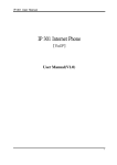
Figure1.1 NVP-300SS use as adapter to connect RJ-11 and the LAN card inside the PC
17
VoIP ATA NVP-300 SERIES USER’S MANUAL Ver.A6
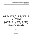
Figure1.2 NVP-300SO use as adapter to connect RJ-11 and the LAN card inside the PC
18
VoIP ATA NVP-300 SERIES USER’S MANUAL Ver.A6
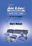
Figure1.3 NVP-300SSO use as adapter to connect RJ-11 and the LAN card inside the PC
3.Do not plug a RJ-11 phone jack connector into the Ethernet port (RJ-45 port). This may damage the
modem Instead; use only twisted-pair cables with RJ-45 connectors that conform to FCC standard.
19
VoIP ATA NVP-300 SERIES USER’S MANUAL Ver.A6
Chapter 3. Hardware Description
This section describes the important parts of the NVP-300 series. It features the front indicators and rear connectors.
3.1 Front Panel
The following figure shows the front panel.
Figure Chapter 2.1 NVP-300SS
Figure Chapter 2.2 NVP-300SO
Figure Chapter 2.3 NVP-300SSO
20
VoIP ATA NVP-300 SERIES USER’S MANUAL Ver.A6
3.2 Front Indicators
The NVP-300SS has Five LED indicators. The following Table shows the description. (Table 2-1)
At a quick glance of the front panel, it will be easy to tell if the modem has power, signal from its Ethernet RJ-45 port or there is
phone line signal RJ-11port
Table 2-1 LED Indicators Description and Operation
LEDs
PWR
Power Good
LED
Ethernet
(WAN/LAN
LED)
Phone set
dialing status
(P1/P2 LED)
Color
Green
Status
Steady
Steady
Green
Blinking
(LINK/ACT)
Steady
Green
Blinking(Ringing)
Descriptions
It will light up (ON) to show that the product power is
good, and system reset OK.
Each RJ45 station port on the Ethernet is assigned
a LED light for monitoring port “Good Linkage”. LED
is normally OFF after the power on operation, but
will light up steadily to show good linkage. And
Flashing to show data transmission.
RJ11 station port on the PHONE1/PHONE2 is
assigned a LED light for dialing function OK, when
you pick up handset If LED flashing indicate getting
a ringing.
21
VoIP ATA NVP-300 SERIES USER’S MANUAL Ver.A6
The NVP-300SO has Six LED indicators. The following Table shows the description. (Table 2-2)
Table 2-2 LED Indicators Description and Operation
LEDs
Color
Status
Descriptions
PWR
Power Good
LED
Green
Steady
It will light up (ON) to show that the product power is
good, and system reset OK.
RDY LED
Green
Steady
It will light up when SIP server register OK.
Steady
Each RJ45 station port on the Ethernet is assigned a
LED light for monitoring port “Good Linkage”. LED is
normally OFF after the power on operation, but will
light up steadily to show good linkage. And Flashing
to show data transmission.
Ethernet
(WAN/LAN
LED)
Green
Phone set
dialing status
(PHONE LED)
Green
POTS(FXO)
Green
Blinking
(LINK/ACT)
Blinking (Ringing)
RJ11 station port on the PHONE is assigned a LED
light for dialing function OK, when you pick up
handset If LED flashing indicate getting a ringing.
Steady
For connecting to the PBX
Steady
22
VoIP ATA NVP-300 SERIES USER’S MANUAL Ver.A6
The NVP-300SSO has Six LED indicators. The following Table shows the description. (Table 2-3)
Table 2-3 LED Indicators Description and Operation
LEDs
PWR
Power Good
LED
Color
Green
Status
Steady
Steady
Ethernet
(WAN/LAN
LED)
Green
Phone set
dialing status
(P1/P2 LED)
Green
POTS(FXO)
Green
Blinking
(LINK/ACT)
Descriptions
It will light up (ON) to show that the product power is
good, and system reset OK.
Each RJ45 station port on the Ethernet is assigned a
LED light for monitoring port “Good Linkage”. LED is
normally OFF after the power on operation, but will
light up steadily to show good linkage. And Flashing
to show data transmission.
Blinking(Ringing)
RJ11 station port on the P1/P2 is assigned a LED
light for dialing function OK, when you pick up
handset If LED flashing indicate getting a ringing.
Steady
For connecting to the PBX
Steady
23
VoIP ATA NVP-300 SERIES USER’S MANUAL Ver.A6
3.3 Rear Panel
The following figure shows the rear connectors
Figure Chapter 2.5 NVP-300 SS (SO) Rear Connectors
Figure Chapter 2.6 NVP-3000SS0 Rear Connectors
24
VoIP ATA NVP-300 SERIES USER’S MANUAL Ver.A6
NVP-300 series Rear Side Connectors
Table 2-4 Rear Side Connectors
Description
Connectors
Type
Rest button
For reboot system
push switch
POTS
For connecting to the PBX
RJ-11(NVP-300SO/SSO only)
Phone1/ Phone 2
For connecting to the telephone or Fax
RJ-11
WAN
For connecting to XDSL/Cable modem
RJ-45
LAN
For connecting to a PC networking card or switched/HUB
RJ-45
Power
For connecting to DC12V/1A or above power adapter
2.0m/m plug
Note:
Power On:
1. Check if the modem is properly connected
2. Verify the power LED is steadily on
25
VoIP ATA NVP-300 SERIES USER’S MANUAL Ver.A6
Chapter 4. Introduction
This user’s manual is for NVP-300 series VoIP terminal adapter. This user’s manual will explain the IVR instruction, web
configuration and command line configuration for the NVP-300 series. Before using the NVP-300 series, some setup processes
are required to make the NVP-300 series work properly. Please refer to the Setup Menu for further information.
4.1 Hardware Overview
The NVP-300 series has the following interfaces for Networking, telephone interface, LED indication, and power connector.
Two RJ-45 Networking interface, these two interfaces support 10/100Mps Fast Ethernet.you can connect one RJ-45 Fast
Ethernet port to the ADSL or Switch, and connect the other one to your computer.
Two RJ-11 Type analog telephone jack interfaces. You can connect two analog telephones terminal adapter.
LED Indication: There are three LED indicators in the NVP-300 series to show the Power, Register, and Off-Hook indication.
26
VoIP ATA NVP-300 SERIES USER’S MANUAL Ver.A6
4.2 Software Overview
Network Protocol
•
•
•
•
•
•
•
SIP v1 (RFC2543), v2(RFC3261)
IP/TCP/UDP/RTP/RTCP
IP/ICMP/ARP/RARP/SNTP
TFTP Client/DHCP Client/ PPPoE Client
Telnet/HTTP Server
DNS Client
NAT/DHCP Server
Tone
•
•
•
•
•
Phone Function
• Volume Adjustment
• Speed dial key
• Phone book
• Flash
IP Assignment
Codec
• G.711: 64k bit/s (PCM)
• G.723.1: 6.3k / 5.3k bit/s
• G.726: 16k / 24k / 32k / 40k bit/s (ADPCM)
• G.729A: 8k bit/s (CS-ACELP)
• G.729B: adds VAD & CNG to G.729
Voice Quality
•
•
•
•
•
Ring Tone
Ring Back Tone
Dial Tone
Busy Tone
Programming Tone
• Static IP
• DHCP
• PPPoE
Security
VAD: Voice activity detection
CNG: Comfortable noise generator
LEC: Line echo canceller
Packet Loss Compensation
Adaptive Jitter Buffer
• HTTP 1.1 basic/digest authentication for Web
setup
• MD5 for SIP authentication (RFC2069/ RFC
2617)
Call Function
QoS
• ToS field
• Call Hold
NAT Traversal
27
VoIP ATA NVP-300 SERIES USER’S MANUAL Ver.A6
• Call Waiting
• Call Forward
• Caller ID
• 3-way conference
DTMF Function
• In-Band DTMF
• Out-of Band DTMF
• SIP Info
• STUN
Configuration
• Web Browser
• Telnet
• IVR/Keypad
Firmware Upgrade
SIP Server
• Registrar Server (three SIP account)
• Outbound Proxy
• TFTP
• Console
• HTTP
28
VoIP ATA NVP-300 SERIES USER’S MANUAL Ver.A6
Chapter 5. IVR Interface for the NVP-300 series
You can use the PSTN phone to configure the NVP-300 series. Please follow the instruction to configure your terminal adapter.
Group
IVR Action
IVR Menu Choice
Parameter(s)
Notes
Function FXS to FXO
None
NVP-300 series FXS+FXO/2FXS+FXO
0*
*
only. Press hook switch once when you
would like to return FXS
The system will change the WAN port to
Setting Set DHCP client
#111#
None
DHCP Client type
Enter IP address using numbers
WAN port DHCP Client will be disabled and
Set
Static
IP
on the telephone key pad. Use
Setting
#112xxx*xxx*xxx*xxx#
WAN port will change to the Static IP type.
Address
the * (star) key when entering a
Set WAN port IP Address
decimal point.
Enter value using numbers on
the telephone key pad. Use the * Must set Static IP first. Set WAN port
Setting Set Network Mask #113xxx*xxx*xxx*xxx#
(star) key when entering a Network Mask
decimal point.
Enter IP address using numbers
Set Gateway
on the telephone key pad. Use Must set Static IP first. Set WAN port
Setting
#114xxx*xxx*xxx*xxx#
IP Address
the * (star) key when entering a Gateway IP Address
decimal point.
Enter IP address using numbers
Set Primary DNS
on the telephone key pad. Use Must set Static IP first. Set WAN port
Setting
#115xxx*xxx*xxx*xxx#
Server
the * (star) key when entering a Primary DNS Server IP Address
decimal point.
Info
Check IP Address #120#
None
IVR will report the LAN port IP address
IVR will report the WAN Port DHCP is
Info
Check IP Type
#121#
None
enabled or disabled.
Check
the
Info
#122#
None
IVR will report current in use VoIP number
Phone Number
29
VoIP ATA NVP-300 SERIES USER’S MANUAL Ver.A6
Check
Network
#123#
Mask
Check Gateway IP
Info
#124#
Address
Group
IVR Action
IVR Menu Choice
Check
Primary
Info
#125#
DNS Server Setting
Info
Check IP Address #126#
Check
Info
Firmware
#128#
Version
Info
Setting Set Codec
#130+[1-8]#
Setting Set Handset Gain
#131+[00~15]#
Set
Handset
#132+[00~12]#
Volume
TFTP Server
Setting
#135#
IP Address
FTP Server
Setting
#136#
IP Address
Setting
Setting Auto config mode
#137+[0~2]#
Function enable call waiting #138#
Function disable call waiting #139#
Function unlock keypad
#190#
None
IVR will report the WAN Port network mask
None
IVR will report the WAN Port gateway IP
address
Notes
IVR will report the WAN Port Primary DNS
server IP Address.
IVR will report the WAN port IP address
None
IVR will report the firmware version
None
Parameter(s)
None
1:G.711 u-Law, 2: G.711 a-Law,
3: G.723.1, 4: G.729a, 5: G.726 You can set the codec you want to the first
16K, 6: G.726 24K, 7: G.726 32K, priority.
8: G.726 40K,
You can set the Handset gain to proper
Handset Gain from 0~15
value, default is 10
You can set the Handset volume to proper
Handset Volume from 0~12
value, default is 10
Set Auto config TFTP Server IP
You can set the TFTP Server IP address
Address
Set Auto config FTP Server IP
You can set the FTP Server IP address
Address
You can set the Auto configuration mode,
0: Disable, 1: TFTP mode, 2:
0: Disable, 1: use TFTP Server, 2: user
FTP mode
FTP Server
None
Enable Call waiting
None
Disable call waiting
None
you have to unlock keypad first, then you
30
VoIP ATA NVP-300 SERIES USER’S MANUAL Ver.A6
can change the setting by keypad.
Function lock keypad
IP mode
Setting
Setting
PSTN mode
Function Reboot
Group
IVR Action
Function Factory Reset
#191#
None
#192#
Set defualt use IP mode
#193#
Set defualt use PSTN mode
#195#
None
IVR Menu Choice
#198#
Parameter(s)
None
31
lock keypad.
Only support 1S1P, provide setting change
default setting to IP mode
Only support 1S1P, provide setting change
default setting to PSTN mode
The system will reboot automatically.
Notes
System will automatically Reboot and
restore to default setting.
WARNING:
ALL
“User-Changeable”
NONDEFAULT
SETTINGS WILL BE LOST! This will
include network and service provider data.
VoIP ATA NVP-300 SERIES USER’S MANUAL Ver.A6
Chapter 6. Setup the NVP-300 series by Web Browser
The NVP-300 series provides a built-in web server. You can use Web browser to configure the NVP-300 series. First please
input the IP address in the Web page. In the end of IP address, please add the port number “:9999”.
Ex:http://192.168.123.1:9999
6.1 Login.
Please input the username and password into the blank field. The default setting is:
1.For Administrator, the username is: root; and the password is: test. If you use the account login, you can configure all the setting.
2.For normal user, the username is: user; and the password is: test. If you use the account login, but you can not configure the SIP
setting.
Click the “Login” button will move into the NVP-300 series web based management information page.
If you change the setting in the Web Management interface, please do remember to click the “Submit” button in that page.
After you finished the change of the setting, click the “Save” function in the left side, and click the Save Button. When you
finished the setting, please click the Reboot function in the left side, and click the Reboot button in that page. After the system
restart, all the setting can work properly.
32
VoIP ATA NVP-300 SERIES USER’S MANUAL Ver.A6
6.2 System Information for the NVP-300 series.
When you login the web page, you can see the NVP-300 series current system information like firmware version, company…
etc in this page.
Also you can see the function lists in the left side. You can use mouse to click the function you want to set up.
33
VoIP ATA NVP-300 SERIES USER’S MANUAL Ver.A6
6.3 Phone Book
The NVP-300 series supports user programming of up to ten phone number, local,international or emergency numbers and/or
IP addresses for fast and easy access.
6.3.1 In Phone Book contains Speed Dial Settings. You can setup the Speed Dial number. If you want to use Speed Dial you just
dial the speed dial number (from 0~9) then press “#”.
6.3.2 In Speed Dial setting function you can add/delete Speed Dial number. You can input maximum 10 entries speed dial list.
If you need to add a phone number into the Speed Dial list, you need to input the position, the name, and the phone number
(by URL type). When you finished a new phone list, just click the “Add Phone” button.
If you want to delete a phone number, you can select the phone number you want to delete then click “Delete Selected” button.
If you want to delete all phone numbers, you can click “Delete All” button.
34
VoIP ATA NVP-300 SERIES USER’S MANUAL Ver.A6
6.4 Phone Setting
In Phone Setting contains Call Forward, SNTP Settings, Volume Settings, Block Setting, Caller ID, Auto Dial Setting, Flash Time
Setting and Call Waiting Setting functions. Please configure the items as follows.
6.4.1 Call Forward function:
you can setup the phone number you want to forward in this page.There are three type of Forward mode. You can choose All
Forward, Busy Forward, and No Answer Forward by click the icon.
All Forward: All incoming call will forward to the number you choosed. You can input the name and the phone number in URL
field. If you select this function, then all the incoming call will direct forward to the speed dial number you choose.
Busy Forward: If you are on the phone, the new incoming call will forward to the number you choosed. You can input the name
and the phone number in URL field.
No Answer Forward: : If you can not answer the phone, the incoming call will forward to the number you choosed. You can
input the name and the phone number in URL field. Also you have to set the Time Out time for system to start to forward the
call to the number you choosed.
6.4.2.4 When you finished the setting, please click the Submit button.
35
VoIP ATA NVP-300 SERIES USER’S MANUAL Ver.A6
6.4.2 SNTP Setting function:
you can setup the primary and second SNTP Server IP Address, to get the date/time information. Also you can base on your
location to set the Time Zone, and how long need to synchronize again. When you finished the setting, please click the Submit
button.
36
VoIP ATA NVP-300 SERIES USER’S MANUAL Ver.A6
6.4.3 Volume Setting function:
you can setup the Handset Volume, Ringer Volume, and the Handset Gain. When you finished the setting, please click the Submit
button.
Handset Volume is to set the volume for you can hear from the handset.
Ringer Volume is to set the ringer volume for you can hear.
PSTN-Out Volume is to set the PSTN volume for you can hear.
Handset Gain is to set the volume send out to the other side’s handset.
PSTN-In Gain is to set the volume send out to the other side’s handset.
37
VoIP ATA NVP-300 SERIES USER’S MANUAL Ver.A6
6.4.4 Block Setting function:
you can setup the Block Setting to keep the phone slience. You can choose Always Block or Block a period.
Always Block: All incoming call will be blocked until disable this feature.
Block Period: Set a time period and the phone will be blocked during the time period. If the “From” time is large than the “To”
time, the Block time will from Day 1 to Day 2.
When you finished the setting, please click the Submit button.
38
VoIP ATA NVP-300 SERIES USER’S MANUAL Ver.A6
6.4.5 Caller ID function:
you can set the device to show Caller ID in your PSTN Phone or IP Phone. There are four selection of Caller ID. You need to base
on your environment to set the Caller ID function for FSK or DTMF.
39
VoIP ATA NVP-300 SERIES USER’S MANUAL Ver.A6
6.4.6 Auto Dial Setting function:
This function is when you input the phone number by the keypad but you don’t need to press “#”. After time out the system will dial
directly.
40
VoIP ATA NVP-300 SERIES USER’S MANUAL Ver.A6
6.4.7 Flash Time Setting function:
When you use the PSTN Phone and you need to press the Hook to do the Flash (Switch to the other phone line or HOLD), this
function is for you to set the time you press the Hook to represent the Flash function.
41
VoIP ATA NVP-300 SERIES USER’S MANUAL Ver.A6
6.4.8 Call Waiting Setting function:
You can Enable/Disable the Call Waiting function, When you are talking with someone, there is a new incoming call, you will hear
the call waiting tone.
42
VoIP ATA NVP-300 SERIES USER’S MANUAL Ver.A6
6.4.9 T.38 Setting function:
You can Enable/Disable the T.38 function.
43
VoIP ATA NVP-300 SERIES USER’S MANUAL Ver.A6
6.5 Network
In Network you can check the Network status, configure the Network Settings and DDNS settings.
6.5.1 Network Status:
You can check the current Network setting in this page.
44
VoIP ATA NVP-300 SERIES USER’S MANUAL Ver.A6
6.5.2 WAN Settings:
In this page you can configure the IP Phone WAN port’s setting. The WAN port is for you to connect to the ADSL Router,
Broadband Router. Also you can use PPPoE to get the WAN IP address from your ISP.
The IP Phone’s default setting is NAT mode. If you don’t need to use the NAT Mode, you can chang to Bridge Mode. If you
change the setting to Bridge Mode, then the LAN setting will not effect and will be the same as WAN port.
The WAN port default is DHCP Client mode, You can change the setting to Fixed IP Mode, or PPPoE Mode.
If you change the WAN port’s setting to Fix IP Mode, then you have to make sure the IP address. Net Mask, Gateway, and
DNS setting is suitable in your current network environment.
If you change the WAN port’s setting to PPPoE Mode, you have to input a correct username/password to get the IP address
from your Internet Service Provider.
When you finished the setting, please click the Submit button.
If there is nothing need to change, please click the Save Change Item in the left side, then click the Save button. The change
you made will save into the system and the system will Reboot automatically.
45
VoIP ATA NVP-300 SERIES USER’S MANUAL Ver.A6
46
VoIP ATA NVP-300 SERIES USER’S MANUAL Ver.A6
6.5.3 LAN Settings:
In this page you can configure the IP Phone LAN port’s setting.
The LAN port’s default IP address is 192.168.123.1, Net Mask is 255.255.255.0., and DHCP Server enabled. The start IP
address if 150, end IP adress is 200. It is not necessary to change the LAN settings.
You can connect your PC to the LAN port, set your PC as DHCP Client mode, then you can get IP addreess from the
NVP-300.
When you finished the setting, please click the Submit button.
If there is nothing need to change, please click the Save Change Item in the left side, then click the Save button. The change
you made will save into the system and the system will Reboot automatically.
47
VoIP ATA NVP-300 SERIES USER’S MANUAL Ver.A6
6.5.4 Network Settings:
You can configure the NVP-300 series Network setting in this page.
The TCP/IP Configuration item is to setup the LAN port’s network environment. You may refer to your current network
environment to configure the NVP-300 series properly.
The PPPoE Configuration item is to setup the PPPoE Username and Password. If you have the PPPoE account from your
Service Provider, please input the Username and the Password correctly.
The Bridge Item is to setup the NVP-300 series Bridge mode Enable/Disable. If you set the Bridge On, then the two Fast
Ethernet ports will be transparent.
When you finished the setting, please click the Submit button.
48
VoIP ATA NVP-300 SERIES USER’S MANUAL Ver.A6
6.5.5 DDNS Setting:
You can configure the DDNS setting in this page. You need to have the DDNS account and input the informations properly. You can
have a DDNS account with a public IP address then others can call you via the DDNS account. But now most of the VoIP
applications are work with a SIP Proxy Server. When you finished the setting, please click the Submit button.
49
VoIP ATA NVP-300 SERIES USER’S MANUAL Ver.A6
6.5.6 VLAN Setting:
You can set the VLAN setting in this page. There are two parts in this page. First one is to set the packets related to the NVP-300,
and the second parts is if you use the VLAN setting in the NAT Mode.
There are two kind of destination packets will come from the VoIP’s WAN port, one kind of packets will go to the VoIP, the other
will go through the LAN port to the PC.
VLAN Packets: if you enable the first VLAN Packets and set the VID, User Priority, and CFI, then all the incoming packets will
be check with the IP Address and the VID.
VID: You can follow your service provider to set your VID.
User Priority: Defines user priority, giving eight (2^3) priority levels. IEEE 802.1P defines the operation for these 3 user priority
bits. Usually this will be defined by your service provider.
CFI: Canonical Format Indicator is always set to zero for Ethernet switches. CFI is used for compatibility reason between
Ethernet type network and Token Ring type network. If a frame received at an Ethernet port has a CFI set to 1, then that frame
should not be forwarded as it is to an untagged port.
When you enable the first VLAN Packets and set the VID, User Priority, and CFI, then all the incoming packets with the
VoIP’s IP address and the same VID will be accept by the VoIP. If the incoming packets with the VoIP’s IP address but the
different VID then the packets will be discard by the VoIP. The Other incoming packets with different IP address will go through
the LAN port to the PC.
NAT VLAN Setting: When you set your device in NAT mode, the VoIP can help you to filter the wrong incoming packets. You
can separate the other device connectd behind the VoIP into 4 VLAN group. You can set different VID for these 4 groups.
When the incoming packets go through the VoIP’s WAN port then the VoIP will check the VID, if the packets is not going to the
VoIP(with the VoIP’s IP address and the correct VID), and the VID is not these four VID you set, then the packets will be
discard by the VoIP.
If there is nothing need to change, please click the Save Change Item in the left side, then click the Save button. The change
you made will save into the system and the system will Reboot automatically.
Note:
NVP-300 series only provide one LAN port, so V-LAN function can't be setted.
50
VoIP ATA NVP-300 SERIES USER’S MANUAL Ver.A6
51
VoIP ATA NVP-300 SERIES USER’S MANUAL Ver.A6
6.6 SIP Settings
In SIP Settings you can setup the Service Domain, Port Settngs, Codec Settings, Codec ID Setting, RTP Setting, RPort Setting and
Other Settings. If the VoIP service is provided by ISP, you need to setup the related informations correctly then you can register to
the SIP Proxy Server correctly.
In Service Domain Function you need to input the account and the related informations in this page, please refer to your ISP
provider. You can register three SIP account in the NVP-300 series. You can dial the VoIP phone to your friends via first enable SIP
account and receive the phone from these three SIP accounts. For the second phone you can use the same way to register.
Display Name: you can input the name you want to display.
User Name: you need to input the User Name get from your ISP.
Register Name: you need to input the Register Name get from your ISP.
Register Password: you need to input the Register Password get from your ISP.
Domain Server: you need to input the Domain Server get from your ISP.
Proxy Server: you need to input the Proxy Server get from your ISP.
Outbound Proxy: you need to input the Outbound Proxy get from your ISP. If your ISP does not provide the information, then
you can skip this item.
Register Period: you need to input the Register Period get from your ISP. This is count in minute.
You can see the Register Status in the Status item. If the item shows “Registered”, then your NVP-300 series is registered to
the ISP, you can make a phone call direcly.If you have more than one SIP account, you can following the steps to register to
the other ISP.
When you finished the setting, please click the Submit button.
52
VoIP ATA NVP-300 SERIES USER’S MANUAL Ver.A6
53
VoIP ATA NVP-300 SERIES USER’S MANUAL Ver.A6
6.6.1 Port Settings:
you can setup the SIP and RTP port number in this page. Each ISP provider will have different SIP/RTPport setting, please refer to
the ISP to setup the port number correctly. When you finished the setting, please click the Submit button.
54
VoIP ATA NVP-300 SERIES USER’S MANUAL Ver.A6
6.6.2 Codec Settings:
you can setup the Codec priority, RTP packet length, and VAD function in this page. You need to follow the ISP suggestion to setup
these items. When you finished the setting, please click the Submit button.
55
VoIP ATA NVP-300 SERIES USER’S MANUAL Ver.A6
6.6.3 Codec ID Setting:
Sometimes 2 VoIP device with different Codec ID will cause the interopability issue. If you are talking with others got some
problems, you may ask the other one what kind of Codec ID he use, then you can change your Codec ID. When you finished the
setting, please click the Submit button.
56
VoIP ATA NVP-300 SERIES USER’S MANUAL Ver.A6
6.6.4 RTP Setting:
you can setup the Out-Band DTMF and send DTMF SIP Info Enable/Disable in this page. To change this setting, please following
your ISP information. When you finished the setting, please click the Submit button.
57
VoIP ATA NVP-300 SERIES USER’S MANUAL Ver.A6
6.6.5 DTMF Setting:
you can setup the InBand DTMF, 2833 Out-Band DTMF and Send DTMF SIP Info Enable/Disable in this page. To change this
setting, please following your ISP information. When you finished the setting, please click the Submit button.
58
VoIP ATA NVP-300 SERIES USER’S MANUAL Ver.A6
6.6.6 RPort Function:
you can setup the RPort Enable/Disable in this page. To change this setting, please following your ISP information. When you
finished the setting, please click the Submit button.
59
VoIP ATA NVP-300 SERIES USER’S MANUAL Ver.A6
6.6.7 Other Settings:
you can setup the Hold by RFC, Voice/SIP QoS and SIP expire time in this page. To change these settings please following your
ISP information. When you finished the setting, please click the Submit button. The QoS setting is to set the voice packets’ priority.
If you set the value higher than 0, then the voice packets will get the higher priority to the Internet. But the QoS function still need to
cooperate with the others Internet devices.
60
VoIP ATA NVP-300 SERIES USER’S MANUAL Ver.A6
6.7 NAT Trans.
In NAT Trans:
You can setup STUN function. These functions can help your NVP-300 series working properly behind NAT.
STUN Setting:
You can setup the STUN Enable/Disable and STUN Server IP address in this page. This function can help your NVP-300 series
working properly behind NAT. To change these settings please following your ISP information. When you finished the setting,
please click the Submit button.
61
VoIP ATA NVP-300 SERIES USER’S MANUAL Ver.A6
6.8 Others
In Others you can setup Auto Config, PTT Setting and ICMP Setting function. The function can configure your VoIP Phone
automatically.
Auto Config: you can setup the Auto Configuration Enable/Disable and auto configuration by FTP or TFTP. You need to select
the way to do the Auto Configuration and set the Server IP address in this page. This function can automatically download the
configure file to setup your NVP-300. When you finished the setting, please click the Submit button.
62
VoIP ATA NVP-300 SERIES USER’S MANUAL Ver.A6
PTT Setting: You can setup the PTT in this page. When you are using different country’s PSTN Phone or connect to different
country’s PSTN Line, you have to set the country’s setting to meet the requirement. When you finished the setting, please click
the Submit button.
ICMP Setting: You can setup the ICMP echo Enable/Disable in this page. This function can disable echo when someone ping
this device, it can avoid haker try to attack the device. When you finished the setting, please click the Submit button.
63
VoIP ATA NVP-300 SERIES USER’S MANUAL Ver.A6
6.9 System Auth.
In System Authority you can change your login name and password.
64
VoIP ATA NVP-300 SERIES USER’S MANUAL Ver.A6
6.10 Save Change
In Save Change you can save the changes you have done. If you want to use new setting in the NVP-300 series, You have to click
the Save button. After you click the Save button, the NVP-300 series will automatically restart and the new setting will effect.
65
VoIP ATA NVP-300 SERIES USER’S MANUAL Ver.A6
6.11 Update
In Update you can update the NVP-300 series’s firmware to the new one or do the factory reset to let the NVP-300 series back
to default setting.
In New Firmware function you can update new firmware via HTTP in this page. You can ugrade the firmware by the following
steps:
1. Select the firmware code type, Risc or DSP code.
2. Click the “Browse” button in the right side of the File Location or you can type the correct path and the filename in File Location
blank.
3. Select the correct file you want to download to the NVP-300 series then click the Update button.
66
VoIP ATA NVP-300 SERIES USER’S MANUAL Ver.A6
In Default Setting you can restore the NVP-300 series to factory default in this page. You can just click the Restore button, then
the NVP-300 series will restore to default and automatically restart again.
67
VoIP ATA NVP-300 SERIES USER’S MANUAL Ver.A6
6.12 Reboot
Reboot function you can restart the NVP-300 series. If you want to restart the NVP-300 series, you can just click the Reboot button,
then the NVP-300 series will automatically.
68
VoIP ATA NVP-300 SERIES USER’S MANUAL Ver.A6
6.13 Auto Answer(NVP-300SO/SSO only)
Auto Answer will auto change from FXS to FXO(PBX) when call in without reply over setting time. Call in persons can call you
again through FXO when NVP-300 series auto change to FXO and hearing a dial tone.
Plese select ON, If you want to enable Auto Answer function on the NVP-300 series, and setting pin code(password) when you
only provide this function to you well know persons.
69
VoIP ATA NVP-300 SERIES USER’S MANUAL Ver.A6
Chapter 7. Engineering webpage
7.1 Engineer usage webpage list
You have to login the system first then change the webpage to crystal.htm manually. In this webpage you will see the list about
engineer webpage. You can change the webpage to what you want.
70
VoIP ATA NVP-300 SERIES USER’S MANUAL Ver.A6
7.2 Update System
In this page you can update the system’s ROM code, IC Test , Default setting and Logo.
Update ROM code. You can update the ROM code from this function. Please be noted that if you update the wrong file or
during the update process the power is off, the system will be crashed.
Update Logo. The Logo specification is “220x170” pixel and need “jepg format” file.
71
VoIP ATA NVP-300 SERIES USER’S MANUAL Ver.A6
7.3 NAT Settings
In this page you can setup the nat function. The WAN setting is for you to set how the get the IP address for the device. The LAN
setting is for the other devices to get the IP address from the device. You can choose to use DHCP server or not.
72
VoIP ATA NVP-300 SERIES USER’S MANUAL Ver.A6
7.4 DMZ Setting
In this page you can setup the DMZ function. You need to enable/disable this function and set the IP address for DMZ.
73
VoIP ATA NVP-300 SERIES USER’S MANUAL Ver.A6
7.5 Virtual Server Settings
In this page you can setup the Virture Server function.
74
VoIP ATA NVP-300 SERIES USER’S MANUAL Ver.A6
7.6 Tones Settings
In this page you can setup the Tone frequency and cadence to meet the requirement.
75
VoIP ATA NVP-300 SERIES USER’S MANUAL Ver.A6
7.7 Speaker Phone Setting
In this page you can setup the Speaker function. This function only support in IP Phone with speaker phone.
76
VoIP ATA NVP-300 SERIES USER’S MANUAL Ver.A6
7.8 VLAN Settings
In this page you can setup the VLAN function.
77
VoIP ATA NVP-300 SERIES USER’S MANUAL Ver.A6
Chapter 8. Setup the NVP-300 series by Telnet
8.1 Login into the NVP-300 series
Please execute “Telnet + NVP-300 series IP”, Then Telnet is ready to connect to the NVP-300 series. Press “Enter” and the
Telnet will show the “Login: “. Input “root” and press the “Enter” button. Then Telnet will show the “Password: “. Input “test” and
press the “Enter” button. Now you already login the NVP-300 series. Please follow the CLI command list to configure the
NVP-300 series with proper instruction and value.
8.2 Using CLI command to configure the NVP-300 series
CLI command list as below:
Item
1
2
3
4
5
6
7
8
9
10
11
12
13
14
15
16
17
Command
?
arp
ipconfig
save
reboot
exit
debugmode
update
auth
nat
dns
ping
sip
ddns
sntp
vlan
time
Description
Show CLI Command
ARP Configuration
Interface Configuration
Save to flash
Reboot
Exit
Enter Debug Mode
Update Flash Code/RAM
Change User Name and Password
NAT Configuration
DNS Configuration
ping [-lN] [IP-addr|host-name]
SIP Configuartion
DDNS Configuartion
SNTP Configuartion
VLAN Configuartion
Get System Time
78
VoIP ATA NVP-300 SERIES USER’S MANUAL Ver.A6
Item
18
19
20
21
22
23
24
25
26
27
28
29
Command
mactab
dump
book
reload
watchdog
phone
weblogo
dsp
addport
cid
slic
ver
Description
Show MAC Learning Table
Read/Write Memory
Edit phone book
Reload Factory Setting
WatchDog Function
Phone Setting
Change Web's logo
Show dsp type
Add Nat Port Mapping
Select slic Cid
read or write slic registers
Firmware Version
Note:
“?” function is to show CLI command list in the screen.
ARP function list as below:
Item
1
2
3
4
5
Command
?
-a
-d
-s
(null)
Description
Show 'arp' Option
Show ARP Table
Delete ARP Table
Set Static ARP Table
Show ARP Table
Ipconfig function list as below:
Item Command
1
?
2
-if0
3
-if1
Description
Show 'ipconfig' Option
Interface 0
Interface 1
79
VoIP ATA NVP-300 SERIES USER’S MANUAL Ver.A6
4
5
6
7
8
-if2
-h
-a
-r
(null)
Interface 2
Set Host Name
Set ARP Cache Expire
Restore Current Setting
Show IP Setting
Ipconfig –ifN function N is 0, 1, 2
Item
1
2
3
4
5
6
7
8
9
10
11
12
13
14
15
16
17
18
19
Command
?
-t
-m
-i
-nm
-g
-dns0
-dns1
-dr
-nat
on
off
-dhcps
-ddns
-bridge
-dev0
-dev1
-dev2
(null)
Description
Show 'ipconfig -ifN' Option
Set Host Type
Set MAC Address
Set IP Address
Set Net Mask
Set Gateway
Set Primary DNS server
Set Secondary DNS server
Set Default Route
Set NAT
Enable Interface
Disable Interface
DHCP Server Setting
Set DDNS
Set Bridge
Set Device 0 Setting
Set Device 1 Setting
Set Device 2 Setting
Show Interface Setting
80
VoIP ATA NVP-300 SERIES USER’S MANUAL Ver.A6
Save function list as below:
Item Command
1
?
2
-book
3
-sys
Description
Show 'save' Option
Save phone book
Save system setting
Reboot function is to restart the system.
Exit function is to exit the CLI.
Debugmode function is to enter the debugmode.
update function list as below:
Item
1
2
3
4
5
6
7
8
9
10
11
12
13
14
Command
?
-os
-dsp
-all
-server
-pcm
-alaw
-ulaw
-g729
-g723
-g726.16
-g726.24
-g726.32
-g726.40
Description
Show 'update' Option
Update OSImage(IP filename)
Update DSP Image(IP filename)
Update All Image(IP filename)
Update Server (IP filename length)
PCM(IP filename)
alaw (IP filename)
ulaw (IP filename)
g729 (IP filename)
g723 (IP filename)
g726.16 (IP filename)
g726.24 (IP filename)
g726.32 (IP filename)
g726.40 (IP filename)
Note:
IP is the TFTP server’s IP address, and the filename is the image you want to download into the system.
81
VoIP ATA NVP-300 SERIES USER’S MANUAL Ver.A6
Auth function list as below:
Item
1
2
3
4
5
6
7
8
9
10
11
12
13
14
Command
?
-admin
-sys0
-sys1
-sys2
-sys3
-sys4
-norm0
-norm1
-norm2
-norm3
-norm4
-ppp
(null)
In each item includes
Item
1
2
3
4
Command
?
-user
-pass
(null)
Description
Show 'auth' Option
Change Administrator user name/password
Change System user0 user name/password
Change System user1 user name/password
Change System user2 user name/password
Change System user3 user name/password
Change System user4 user name/password
Change Normal user0 user name/password
Change Normal user1 user name/password
Change Normal user2 user name/password
Change Normal user3 user name/password
Change Normal user4 user name/password
Change PPP user name/password
Show auth Setting
Description
Show 'auth' Option
Change User Name.'auth -sys3 -user xxx '
Change Password. 'auth -sys3 -pass xxx xxx'
Show auth's System/PPP Setting
Note:
If you want to change the password, you need to type the password twice in the CLI.
Nat function list as below:
82
VoIP ATA NVP-300 SERIES USER’S MANUAL Ver.A6
Item
1
2
3
4
Command
?
-vs
-dmz
(null)
Description
Show 'nat' Option
Set 'nat -vs' Option
Set 'nat -dmz' Option
Show NAT Setting
Item
1
2
3
4
5
Command
?
on
off
-ip
(null)
Description
Show 'nat -dmz' Option
EnableDMZ
EnableDMZ
Set DMZ IP address
Show DMZ Setting
In DMZ item includes
Dns function list as below:
Item Command
1
?
2
-q
3
(null)
Description
Show 'dns' Option
DNS query. dns -q domain-name
Show DNS Table
Item Command
1
?
2
-l
3
(null)
Description
Show 'ping' Option
ping [-l N] [IP-addr|host-name]
ping [IP-addr|host-name]
Item Command
1
?
2
-proxy0
Description
Show 'sip' Option
sip -proxy0
Ping function list as below:
Sip function list as below:
83
VoIP ATA NVP-300 SERIES USER’S MANUAL Ver.A6
3
4
5
6
7
8
9
10
11
12
13
14
15
16
17
18
19
20
21
22
23
24
-proxy1
-proxy2
-upnp
-exts
-extr
-sipp
-rtpp
-stun
-rport
-sserver
-out
-dump
-log
-drtp
-rtpnc
-wanip
-nattype
-hbyrfc
-dereg
-restart
-jbt
(null)
sip -proxy1
sip -proxy2
sip -upnp on/off/show
sip -exts sip upnp external-port
sip -extr rtp upnp external-port
sip udp port
sip rtp port
sip -stun on/off
sip -rport on/off
sip -sserver stun-server
sip -out outbound-proxy
sip –dump
sip -log on/off
sip -drtp 0/1/2
sip -rtpnc on/off
sip –wanip
sip –nattype
sip –hbyrfc
sip -dereg
sip -restart
sip -jitter buffer Threshold
Show SIP Setting
Command
?
-type
-host
-wild
-mx
Description
Show 'ddns' Option
Set DDNS Type
Set Host Name
Set Wild Card Mode
Set Mail Exchanger
Ddns function list as below:
Item
1
2
3
4
5
84
VoIP ATA NVP-300 SERIES USER’S MANUAL Ver.A6
6
7
8
9
10
Set Mail Exchanger Mode
Set Offline Mode
Set Login User Name
Set Login Password
Show DDNS Setting
Command
?
-on
-off
-ip1
-ip2
-mode
-zone
-adjust
(null)
Description
Show 'sntp' Option
Enable SNTP Client
Disable SNTP Client
Set SNTP Server1 IP
Set SNTP Server2 IP
Set SNTP Client Mode
Set GMT Time Zone: [+|-][hour]:[min]
Set Adjustment Time: [second]
Show SNTP Setting
Sntp function list as below:
Item
1
2
3
4
5
6
7
8
9
-backmx
-offline
-user
-pass
(null)
Vlan function list as below:
Item Command
1
?
2
-tx
3
-rx
4
(null)
Description
Show 'vlan' Option
Tx Vlan setting
Rx Vlan setting
Show Vlan Setting
Item Command
1
?
2
-t
3
-d
Description
Show 'Time' Option
Modify Time: hour:min:sec
Modify date: year:mon:date
Time function list as below:
85
VoIP ATA NVP-300 SERIES USER’S MANUAL Ver.A6
4
Show Data & Time
Mactab function is to show MAC learning table.
Dump function list as below:
Item Command
1
?
2
-r
3
-w
Description
Show 'dump' Option
dump -r XXXXxxxx
dump -w XXXXxxxx XX
Book function list as below:
Item
1
2
3
4
5
(null)
Command
?
-a
-c
-s
-p
Description
Show 'book' Option
Show answer list
Show call list
speed dial
phone book
Reload function is to Reload Factory Setting, please make sure you want to do the factory reset.
Watchdog function list as below:
Item
1
2
3
4
Command
?
on
off
(null)
Description
Show 'WatchDog' Option
Enable WatchDog
Disable WatchDog
Show WatchDog Setting
Phone function list as below:
Item Command
1
?
Description
Show 'phone' Option
86
VoIP ATA NVP-300 SERIES USER’S MANUAL Ver.A6
2
3
4
5
6
7
Weblogo function list as below:
Item
1
2
3
4
-autoanswer
-vol
-block
-ring
-forward
(null)
Command
?
-on
-off
(null)
phone auto answer
Volume setting
Block Incoming call
Set Melody Ringer
Auto-forward Incall to Phone[0-9] in
Book
Show Phone Setting
Description
Show 'weblogo' Option
Vender Logo
Crystal media Logo
Show weblogo Setting
Dsp function is to show dsp code type.
Dport function is to add Nat Port Mapping 8.3.1.27 cid function
Item Command
1
?
2
-off
3
-1
4
-2
5
-3
6
-4
7
-5
Description
Show 'cid' Option
Disable Slic Cid signal
Tx FSK after 1st Ring
Tx FSK before 1st Ring
Tx DTMF before 1st Ring
Tx FSK with Line reversal before 1st
Ring
Tx DTMF with Line reversal before 1st
Ring
87
VoIP ATA NVP-300 SERIES USER’S MANUAL Ver.A6
8
9
10
FSK cid with time mseeage
Single type FSK CID
Show Cid Option
Command
?
-ring
-r
-w
-a
(null)
Description
Show 'slic' Option
Issue Ring signal
read slic addr
write slic addr
read all slic reg
Show slic register
Slic function list as below:
Item
1
2
3
4
5
6
-time
-single
(null)
Ver function is to show Firmware Version.
88
VoIP ATA NVP-300 SERIES USER’S MANUAL Ver.A6
Chapter 9. How to make a phone call
When your NVP-300 series is configured properly, you can make a phone call to your friend in the same Service provider.
If you want to make a phone call, you can dial the phone number and press “#” button to start to dial the phone number.
The NVP-300 also provides some functions that list as below:
1. Call Waiting: When a new call is coming while you are talking, you can push the Flash button to switch to the new call. You
can push the Flash button to switch between the two calls.
2. Call Hold: You can push the Hold key to hold the current call for a while, then push Hold key again to keep talking.
3. 3-way conference: If you want to make a 3-way conference call, you can make a phone call to the first phone number.
After the call is established, push the Flash button then you can hear the Dial tone, then make a phone
call to the second phone number. When the second call is established, press the Flash button again. In
the 2-port NVP-300, only one FXS port can support 3-way conference function, and one is G.723/G.729A,
the other one is G.711.
89
VoIP ATA NVP-300 SERIES USER’S MANUAL Ver.A6
Chapter 10. Get a FWD account
1. The website is www.freeworlddialup.com; you can apply an account to use the VoIP communication. You can follow the
instruction to input the information. After you finished, you will receive a mail sent by the FWD mail system, you will get the
account information in the mail.
2. When you got the account, you can setup the related information into the NVP-300 series.
3. You can setup the related information into the NVP-300 series by web browser. Also you can use Telnet, Console via CLI
command to configure the NVP-300 series. You need to input the Proxy Name, Domain Name, Register Name, and
password. The Display Name you can input what you want to let others see.
4. After you registered to the SIP Server, you can try to call your friends who also registered in the same SIP Server. You just
need to dial your friend’s user name (registered name) and press “#” then you can make a phone call to your friend.
5. If you want to make a phone call to the other in the internet, first you need to registered in a Proxy Server (with SIP Server IP,
Domain IP, registered name, Password), make sure you already enable Stun function, then you can try.
90
VoIP ATA NVP-300 SERIES USER’S MANUAL Ver.A6
Chapter 11. How to change from FXS to FXO
Please pick up hand set, then dial “0” + “*” key when you would like to change from FXS to FXO.
Please press hook switch once when you would like to return FXS.
Note:
NVP-300SO/SSO default on FXS mode.
91
VoIP ATA NVP-300 SERIES USER’S MANUAL Ver.A6
Appendix A: Dial Plans
The SIP code will allow provisioning (via web browser) of the dial plan. A dial plan gives the unit a map to determine
when a complete number has been entered and should be passed to the gatekeeper for resolution into an IP address.
Dial plans are expressed using the same syntax as used by MGCP NCS specification.
The formal syntax of the dial plan is described by the following notation:
Digit ::= "0" | "1" | "2" | "3" | "4" | "5" | "6" | "7" | "8" | "9"
Timer ::= "T" | "t"
Letter ::= Digit | Timer | "#" | "*" | "A" | "a" | "B" | "b" | "C" | "c"| "D" | "d"
Range ::= "X" | "x" -- matches any digit
| "[" Letters "]" -- matches any of the specified letters
Letters::= Sub range | Sub range Letters
Sub range::= Letter -- matches the specified letter
| Digit "-" Digit -- matches any digit between first and last
Position::= Letter | Range
String Element::= Position -- matches any occurrence of the position
| Position "." -- matches an arbitrary number of occurrences
including 0
String ::= String Element | String Element String
String List::= String | String "|" String List
Dial Plan::= String | "(" String List ")"
A dial plan, according to this syntax, is defined either by a (case insensitive) string or by
a list of strings. Regardless of the above syntax a timer is only allowed if it appears in
the last position in a string (12T3 is not valid). Each string is an alternate numbering
scheme. The unit will process the dial plan by comparing the current dial string against
the dial plan, if the result is under qualified (partial matches at least one entry) then it
will do nothing further. If the result matches or is over-qualified (no further digits could
possibly produce a match) then send the string to the gatekeeper and clear the dial string.
The Timer T is activated when it is all that is required to produce a match. The period of
timer T is 4 seconds. For example a dial plan of (xxxT|xxxxx) will match immediately
92
VoIP ATA NVP-300 SERIES USER’S MANUAL Ver.A6
if 5 digits are entered, it will also match after a 4-second pause when 3 digits are entered.
Simple Dial Plan
Allows dialing of 7 digit numbers (e.g. 5551234) or an operator on 0. Dial plan is
(0T|xxxxxxx)
Non-dialed Line Dial Plan
As soon as handset is lifted, the unit contacts the gatekeeper (used for systems where
DTMF detection is done in-call). Dial plan is (x.) i.e. match against 0 (or more) digits.
Note: the dot ‘.’
Complex Dial Plan
Local operator on 0, long distance operator on 00, four digit local extension number
starting with 3,4 or 5, seven digit local numbers are prefixed by an 8, two digit star
services (e.g. 69), ten digit long distance prefixed by 91, and international numbers
starting with 9011+variable number of digits.
Dial plan for this is:
(0T|00T|[3-5]xxx|8xxxxxxx|*xx|91xxxxxxxxxx|9011x.T)
93
VoIP ATA NVP-300 SERIES USER’S MANUAL Ver.A6
Symbol explan:
x or X
+
0,1,2,3,4,5,6,7,8,9
or
Replace rule: If replace prefix code is ON and prefix number is matched with rule then 005 will replace prefix.
Auto Dial Time : Stop dialing after seconds then send dial number out
Dial Plan: When match with pattern then send dial number out but if fisrt digit is ‘0’ then dial plan
will be ignored.
Example:
*xx
#xx
10x
11x
Xxxxxxxx
If matched with one of *00,*01….*99 then will send number out
If matched with one of #00,#01….#99 then will send number out
If matched with one of 100,101….109 then will send number out
If matched with one of 110,111….119 then will send number out
If dial with 8 digits then send number out
94
VoIP ATA NVP-300 SERIES USER’S MANUAL Ver.A6
Auto Prefix : Number for add before dial number
Prefix Unset Plan : When first digit or dial number match with pattern then ignore auto prefix
0
1
Xxxxx
Xxxxxx
Iignore auto prefix if first digit is ‘0’
Ignore auto prefix if first digit is ‘1’
dial numbers are 4 digits ignore auto prefix
dial numbers are 5 digits ignore auto prefix
95
VoIP ATA NVP-300 SERIES USER’S MANUAL Ver.A6
Appendix B:
Cable Requirement
A CAT 3,4 or 5 UTP (unshielded twisted pair) cable is typically used
To connect the Ethernet device to the modem.
A 10Base-T cable often consists of four pairs of wires, two of which are used for transmission. The connector at the end of the
10Base-T cable is referred to as an RJ-45 connector and it consists of eight pins.
The Ethernet standard uses pins 1,2,3 and 6 for data transmission purposes.
Table
PIN
1
2
3
4
5
6
7
8
RJ-45 Ethernet Connector
MNEMONIC
TX+
TXRX+
NC
NC
RXNC
NC
Pin out Assignments
FUNCTION
Ethernet differential Transmit signal(+)
Ethernet differential Transmit signal(-)
Ethernet differential receive signal(+)
Unused
Unused
Ethernet differential receive signal(-)
Unused
Unused
Standard telephone wire of any gauge or type-flat, twisted or quad is used to connect the Modem to the telephone network. A
telephone cable typically consists of three pairs of wires, one of which is used for transmission. The connector at the end of
the telephone cable is called RJ-11 connector and it consists of six pins. POTS (plain old telephone services) use pins 3 and 4
for voice transmission. A telephone cable is shown below.
96
VoIP ATA NVP-300 SERIES USER’S MANUAL Ver.A6
Figure Telephone cable
A
B
The A and B connectors on the rear of the modem are RJ-11 connectors. These connectors are wired identically. The
RJ-11 connectors have six positions, two of which are wiring, The Modem uses the center two pins. The pin out
assignment for these connectors is presented below.
Table
Pin#
1
2
3
4
5
6
RJ-11 Pin
MNEMONIC
NC
NC
TIP
RING
NC
NC
out Assignments
FUNCTION
Unused
Unused
POTS
POTS
Unused
Unused
97
VoIP ATA NVP-300 SERIES USER’S MANUAL Ver.A6
Appendix C: Product Specification
Product Name:VOIP with Router Adaptor
Application: Home networking solution
Product Specification:
:
Hardware
Digital Signal Processors & Control Processor System On Chip (SOC) for Network Processing and DSP
Application
MIPS-X5 unified RISC and DSP core (up to 180 DSP MIPS)
384K bytes on-chip RAM, 16-way interleaved with single cycle access
16-K byte cache
Low power, 1.8V core voltage, 3.3V I/O voltage
2M bytes flash memory
I/O
2 Standard 10/100 Base-TX RJ 45 interface for 2 FXS model
2 RJ 11 Loop Start interfaces for FXS
Mechanical, Environment & Power
Dimension: L x W x H =184mm x 146mm x 40mm
Operating temperature: 0°C to 50°C (32 to 122 F)
Operating humidity: 10% to 95% (non-condensing)
Storage temperature: -10 to 60°C (14 to 140F)
98
VoIP ATA NVP-300 SERIES USER’S MANUAL Ver.A6
AC-to-DC power supply (12VDC, 120 VAC, 60 Hz. For US or 12VDC, 230VAC,50Hz for Europe)
Power consumption : 5.5 watt (Typical)
Compliant
CE
FCC part 15 A
Software
Compression algorithms: ITU G. 711, G.723, G726, G.729A/B and T.38 Fax Relay
Hybrid echo cancellation G.168 (16 ms)
Auto switch between Fax and voice
DTMF tone detection/regeneration
Comfort Noise Generation (CNG)
User programmable Call Progress detection/generation
Voice Activity Detection (VAD)
Fax
Facsimile protocol(option): T.38
Real-time fax over IP
DTMF tone detection/regeneration
Management Tools
HTTP Server
TFTP and flash memory for remote software download and upgrade
99
VoIP ATA NVP-300 SERIES USER’S MANUAL Ver.A6
SIP Protocol Stack
Compliant with SIP v2.0 (RFC 3261)
MGCP Protocol Stack
Compliant with MGCP protocol specifications (RFC 3435)
Lan / Wan Functions
Tagging VLAN(IEEE802.1q)
QOS (IEEE802.1p)
DHCP Server
PPPOE
NAT
Firewall
SNMP(V1/V2)
Chipset:Crystal Media
100
VoIP ATA NVP-300 SERIES USER’S MANUAL Ver.A6
Appendix D: Troubleshooting
The NVP-300 can be easily monitored through its comprehensive panel indicators. These indicators assist the network
manager in identifying problems the hub may encounter. This section describes common problems you may encounter and
possible solutions
1.
2.
Symptom:
Power LED indicator does not light up (green) after power on.
Cause:
Defective External power supply
Solution:
Cheek the power plug by plugging in another that is functioning properly. Check the power cord with
another device. If these measures fail to resolve the problem, have the unit power supply replaced
by a qualified distributor.
Symptom:
WAN/LAN LED indicator does not light up (green) after making a connection.
Cause:
Solution:
Network interface (e.g, a network adapter card on the attached device), network cable, or switch
port is defective.
2.1 Power off for the NVP-300.
2.2 Verify that the switch and attached device are powered on.
2.3 Be sure the cable is plugged into both the switch and corresponding device.
2.4 Verify that the proper cable type is used and its length does not exceed specified limits.
2.5 Check the NVP-300 on the attached device and cable connections for possible defects.
2.6 Replace the defective NVP-300 or cable if necessary.
101
VoIP ATA NVP-300 SERIES USER’S MANUAL Ver.A6
3.
Symptom:
Phone 1/2 LED indicator does not light up (green) after making a connection.
Solution:
3.1 Be sure the phone wire is plugged into both the NVP-300 and phone set.
3.2 sure the phone set is analog type and on hang on status
3.3 ck the NVP-300 on the phone set and cable connections for possible defects
3.4 Replace the defective NVP-300 or phone set if necessary
System Diagnostics
Power and Cooling Problems
If the POWER indicator does not turn on when the power cord is plugged in, you may have a problem with the power outlet,
power cord, or internal power supply as explained in the previous section. However, if the unit power is off after running for a
while, check for loose power connections, power lost or surges at the power outlet, and verify that the fan on back of the unit is
unobstructed and running prior to shutdown. If you still cannot isolate the problem, then the internal power supply may be
defective. In this case, contact your dealer.
Installation
Verify that all system components have been properly installed. If one or more components appear to be
malfunctioning (e.g., the power cord or network cabling), test them in an alternate environment where you are sure that
all the other components are functioning properly.
Transmission Mode
The default method of selecting the transmission mode for RJ-45 ports is 10/100 Mbps ETHERNET, for RJ-11 port are Voice,
Therefore, if the Link signal is disrupted (e.g., by unplugging the network cable and plugging it back in again, or by resetting
the power), the port will try to reestablish communications with the attached device via auto-negotiation. If auto-negotiation
fails, then communications are set to half duplex by default. Based on this type of industry-standard connection policy, if you
are using a full-duplex device that does not support auto-negotiation, communications can be easily lost (i.e., reset to the
102
VoIP ATA NVP-300 SERIES USER’S MANUAL Ver.A6
wrong mode) whenever the attached device is reset or experiences a power fluctuation. The best way to resolve this problem
is to upgrade these devices to a version that supports Ethernet and analog phone set.
Physical Configuration
If problems occur after altering the network configuration, restore the original connections, and try to track the problem down by
implementing the new changes, one step at a time. Ensure that distance of cable and other physical aspects of the installation
do not exceed recommendations
System Integrity
As a last resort verify the switch integrity with a power-on reset. Turn the power off and then on several times. If the problem
still persists after you have completed all the preceding diagnoses, contact your dealer
FAQ:
1
Problem:
Answer:
This is the first time for me to configure VOIP gateway, unfortunately your product manual relate
with persons who had some previous knowledge about VOIP protocols, SIP and others.
So all I want to learn now is how can I connect two phones connected to two gateways on LAN, and
how can I do the same on WAN
For example: if I will connect two gateways on the same LAN and I will give the first IP 192.168.1.1
and the other 192.168.1.2, and I will connect one phone set to each gateway, so how can I
communicate between the two phone sets. How can I dial?
First,the checks your device whether without any error .Then get in your computer TCP/IP
setting,you must choose"Obtain WAN configuration dynamically".Finally,reference our
VoIP_User_Manual A.3(WAN,LAN,and SIP setting) to configuration dynamically.
103
VoIP ATA NVP-300 SERIES USER’S MANUAL Ver.A6
2
Problem:
Answer:
Note:
3
Problem:
Answer:
Attached my account details with a VOIP service provider Please tell me what settings I have to
enter in the SIP configuration page in all fields especially in
RTP port number
Dial Plan
Line1 Gain Control
Tone (Case after making any configuration I have a very strange tone when I pick up the
handset, it seems like busy tone but its faster)
First,you must register account number on SIP server. Then you'll get the user
name,password..,immediately after open the browser to inputing "192.168.1.1".(But the premise is
your computer necessarily must choose "Obtain WAN configuration dynamically" on TCP/IP
setting.) After inputing the user number and password,you'll configure the setting for this issue.You
can set the user1&user2's phone number in the SIP configuration page.
We suggest you don't need to setting it.(RTP port number,Dail plan,Line1 Gain Control,Tone)
I have already registered in SIP VOIP service, and I have send to you my account details including
number, User name, password and SIP settings. Also I have obtained the WAN to be configured
dynamically, and it obtained an IP I have configured the server settings in the SIP configuration
page, and after configuring the server settings, the tone of the phone changes, it gives me a tone as
the busy tone (but its faster).
Also I have set the User1 Phone Number, including User name & Password (Attached)
Also I didn’t setting any of (RTP port number, Dial plan, Line1 Gain Control, Tone)
It needs to open ˇ (Send Registration Request with Expire Time ) function to select to register sip
server. This function lies in sip server page.
104
VoIP ATA NVP-300 SERIES USER’S MANUAL Ver.A6
4
Problem:
Answer:
5
Problem:
Answer:
6
Problem:
Answer:
Could you tell me whether NVP-300SO supports Caller ID for PSTN? Our customer tests NVP300SO and he tells that NVP-300SO supports Caller ID for IP Network, but it doesn't support Caller
ID for PSTN (he uses FSK). He tells that NVP-300SO doesn't send Caller ID to IP. Could you check
it? Why isn't there any informations about NVP-300SO and NVP-300SSO on you webside?
You can set NVP-300SO to show Caller ID in your PSTN Phone or IP Phone, we support four of
Caller ID mode, such as no display call ID; display call ID before ring; display call ID after ring; and
support DTMF modulation. It must be base on your environment to set properly the Caller ID mode
for FSK or DTMF, as your customer set that on FSK was failure, please try to set that on DTMF.
This is the first time for me to configure VOIP gateway, that have some noise when I want to dial.
How can I dial?
There is this kind of phenomenon is normally, please press “redial” when you to meet this kind of
condition.
If the DHCP using default set in the device? Mean if I first time connect device and have DHCP in
the network, he must get the ip? Is the dial tone start only when network settings ok?
If you just would like to got Dial tone start, you don't need to change anything, you just prepare one
analog phone set connectity to phone 1 or phone2 of NVP-300SSO, now you get busy tone, if no
busy tone please check between phone set and NVP-300SSO both connecting whether ok.
Then you must prepare one Ethernet link to LAN or WAN port of NVP-300SSO, and LAN/WAN port
link LED should be on. If you don't have to connect LAN or WAN, you can't got dial tone start from
FXS port by phone1 or phone2.
105
VoIP ATA NVP-300 SERIES USER’S MANUAL Ver.A6
7
Problem:
Answer:
Our costumer wants to have 2 VLAN's on 1 (WAN) port. He wants 1 VLAN for voice and 1 VLAN for
data.
Is it possible to configure to configure 2 VLAN's on 1 phisical WAN port? And how to do it? Olny in
VLAN Configuration section? or maybe also in WAN Configuration?
NVP-300 series only provide one LAN port, so it can't be setted VLAN groups.
106
VoIP ATA NVP-300 SERIES USER’S MANUAL Ver.A6
Appendix E: Compliance and Safety Information
FCC Radio Frequency Interference Statement
This equipment has been tested and found to comply with the limits for a computing device, pursuant to Part 15 of FCC
class B rules. These limits are designed to provide reasonable protection against harmful interference when the equipment
is operated in a commercial environment. This equipment generate, uses and can radiate radio frequency energy and, if
not installed and used in accordance with the instructions, may cause harmful interference to radio communications.
However, there is no guarantee that interference will not occur in a particular installation. If this equipment does cause
harmful interference to radio or television reception, which can be determined by turning the equipment off and on, the user
is encouraged to try to correct the interference by one or more of the following measures:
1. Reorient or relocate the receiving antenna.
2. Increase the separation between the equipment and receiver.
3. The equipment and the receiver should be connected to outlets on separate circuits.
4. Consult the dealer or an experienced radio/television technician for help.
Changes or modifications not expressly approved by the party responsible for compliance could void the user’s authority to
operate the equipment.
If this telephone equipment causes harm to the telephone network, the telephone company will notify you in advance that
temporary discontinuance of service may be required. But if advance notice isn’t practical, the telephone company will
notify the customer as soon as possible. Also, you will be advised of your right to file a complaint with the FCC if you
believe it is necessary.
The telephone company may make changes in its facilities, equipment, operations or procedures that could affect the
proper functioning of your equipment. If they do, you will be notified in advance in order for you to make necessary
modifications to maintain uninterrupted service.
This equipment may not be used on coin service provided by the telephone company. Connection to party lines is subject
to state tariffs.
107
VoIP ATA NVP-300 SERIES USER’S MANUAL Ver.A6
Important Safety Instructions
Caution: The direct plug-in wall transformer serves as the main product for disconnecting. The socket outlet shall be
installed near the product and be readily accessible.
Caution: Use only the power supply included with this product. In the event the power supply is lost or damaged:In the
United States, use only with CSA certified or UL listed Class 2 power supply.
IN Europe, use only with CE certified power supply.
Do not use this equipment near water, for example in a wet basement.
Avoid using a telephone during an electrical storm. There may be a remote risk of electrical shock from lightning.
Do not use the telephone to report a gas leak in the vicinity of the leaking area.
If you experience trouble with this unit, please contact customer service of your dealer immediately.
DO NOT DISASSEMBLE THIS EQUIPMENT. It does not contain any user serviceable components.
108
VoIP ATA NVP-300 SERIES USER’S MANUAL Ver.A6
FCC Warning
This equipment has been tested to comply with the limits for a Class A digital device, pursuant to Part
15 of the FCC Rules. These limits are designed to provide reasonable protection against harmful
interference when the equipment is operated in a commercial environment. This equipment can
generate, use, and radiate radio frequency energy and, if not installed and used in accordance with
the instruction manual, may cause harmful interference to radio communications. Operation of this
equipment in a residential area is likely to cause harmful interference in which case the user will be required to correct the
interference at owner’s expense.
CE Mark Warning
This is a class B product. In a domestic environment, this product may cause radio interference in which
case the user may be required to take adequate measures.
WEEE Warning
To avoid the potential effects on the environment and human health as a result of the presence of
hazardous substances in electrical and electronic equipment, end users of electrical and electronic
equipment should understand the meaning of the crossed-out wheeled bin symbol. Do not dispose of
WEEE as unsorted municipal waste and have to collect such WEEE separately.
109
VoIP ATA NVP-300 SERIES USER’S MANUAL Ver.A6
Warranty
The original owner of this package will be free from defects in material and workmanship for one-year parts after purchase.
For the warranty to apply, you must register your purchase by returning the registration card indicating the date of purchase.
There will be a minimal charge to replace consumable components, such as fuses, power transformers, and mechanical
cooling devices. The warranty will not apply to any products which have been subjected to any misuse, neglect or accidental
damage, or which contain defects which are in any way attributable to improper installation or to alteration or repairs made or
performed by any person not under control of the original owner.
The above warranty is in lieu of any other warranty, whether express, implied, or statutory, including but not limited to any
warranty of merchantability, fitness for a particular purpose, or any warranty arising out of any proposal, specification, or
sample. Shall not be liable for incidental or consequential damages. We neither assumes nor authorizes any person to assume
for it any other liability.
Note: Please do not tear off or remove the warranty sticker as shown, otherwise the warranty will be void.
110
VoIP ATA NVP-300 SERIES USER’S MANUAL Ver.A6
Chinese SJ/T 11364-2006
有 毒 有 害 物 质 或 元 素
铅(Pb)
汞(Hg)
镉(Cd)
六价铬[Cr(VI)]
多溴联苯(PBB)
结构壳体
○
○
○
○
○
电路组
○
○
○
○
○
电源供应器
○
○
○
○
○
风扇
○
○
○
○
○
线材
○
○
○
○
○
包装及配件
○
○
○
○
○
○:表示该有毒物质在该部件所有均质材料中的含量均在 SJ/T 11364/2006 标准规定的限量要求以下。
╳:表示该有毒物质至少在该部件的某依均质材料中的含量超出 SJ/T 11364-2006 标准规定的限量要求。
上述规范仅适用於中国法律
部件名称
111
多溴二苯醚(PBDE)
○
○
○
○
○
○