1
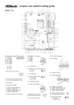
EMX-780E AMD Athlon/ Athlon X2/ Quad-Core™ AMD Phenom™ Mini ITX Motherboard with AMD RS780E + SB710 Chipset Quick Installation Guide 1st Ed – 6 August 2011 Part No. E2017780E00R EMX-780E Quick Installation Guide FCC Statement THIS DEVICE COMPLIES WITH PART 15 FCC RULES. OPERATION IS SUBJECT TO THE FOLLOWING TWO CONDITIONS: (1) THIS DEVICE MAY NOT CAUSE HARMFUL INTERFERENCE. (2) THIS DEVICE MUST ACCEPT ANY INTERFERENCE RECEIVED INCLUDING INTERFERENCE THAT MAY CAUSE UNDESIRED OPERATION. THIS EQUIPMENT HAS BEEN TESTED AND FOUND TO COMPLY WITH THE LIMITS FOR A CLASS "A" DIGITAL DEVICE, PURSUANT TO PART 15 OF THE FCC RULES. THESE LIMITS ARE DESIGNED TO PROVIDE REASONABLE PROTECTION AGAINST HARMFUL INTERFERENCE WHEN THE EQUIPMENT IS OPERATED IN A COMMERCIAL ENVIRONMENT. THIS EQUIPMENT GENERATES, USES, AND CAN RADIATE RADIO FREQUENCY ENERGY AND, IF NOT INSTATLLED AND USED IN ACCORDANCE WITH THE INSTRUCTION MANUAL, MAY CAUSE HARMFUL INTERFERENCE TO RADIO COMMUNICATIONS. OPERATION OF THIS EQUIPMENT IN A RESIDENTIAL AREA IS LIKELY TO CAUSE HARMFUL INTERFERENCE IN WHICH CASE THE USER WILL BE REQUIRED TO CORRECT THE INTERFERENCE AT HIS OWN EXPENSE. Notice This guide is designed for experienced users to setup the system within the shortest time. For detailed information, please always refer to the electronic user's manual. Copyright Notice Copyright 2011 Avalue Technology Inc., ALL RIGHTS RESERVED. No part of this document may be reproduced, copied, translated, or transmitted in any form or by any means, electronic or mechanical, for any purpose, without the prior written permission of the original manufacturer. 2 EMX-780E Quick Installation Guide Quick Installation Guide 1. Getting Started 1.1 Safety Precautions Warning! Always completely disconnect the power cord from your chassis whenever you work with the hardware. Do not make connections while the power is on. Sensitive electronic components can be damaged by sudden power surges. Only experienced electronics personnel should open the PC chassis. Caution! Always ground yourself to remove any static charge before touching the CPU card. Modern electronic devices are very sensitive to static electric charges. As a safety precaution, use a grounding wrist strap at all times. Place all electronic components in a static-dissipative surface or static-shielded bag when they are not in the chassis. Always note that improper disassembling action could cause damage to the motherboard. We suggest not removing the heatsink without correct instructions in any circumstance. If you really have to do this, please contact us for further support. 1.2 Packing List Before you begin installing your single board, please make sure that the following materials have been shipped: 1 x EMX-780E Mini ITX Main Board 2 x SATA Cable kit 1 x DVD-ROM contains the followings: — User’s Manual (this manual in PDF file) — LAN drivers and utilities — Audio drivers and utilities EMX-780E Quick Installation Guide 3 EMX-780E Quick Installation Guide 2. Hardware Configuration 4 EMX-780E Quick Installation Guide Quick Installation Guide 2.1 Product Overview EMX-780E Quick Installation Guide 5 EMX-780E Quick Installation Guide 2.2 Jumper and Connector List You can configure your board to match the needs of your application by setting jumpers. A jumper is the simplest kind of electric switch. It consists of two metal pins and a small metal clip (often protected by a plastic cover) that slides over the pins to connect them. To “close” a jumper you connect the pins with the clip. To “open” a jumper you remove the clip. Sometimes a jumper will have three pins, labeled 1, 2, and 3. In this case, you would connect either two pins. The jumper settings are schematically depicted in this manual as follows: A pair of needle-nose pliers may be helpful when working with jumpers. Connectors on the board are linked to external devices such as hard disk drives, a keyboard, or floppy drives. In addition, the board has a number of jumpers that allow you to configure your system to suit your application. If you have any doubts about the best hardware configuration for your application, contact your local distributor or sales representative before you make any changes. The following tables list the function of each of the board’s jumpers and connectors. Jumpers Label Function Note CN5 CF mode select 3 x 2 header, pitch 2.0mm CN6 LVDS power select 3 x 2 header, pitch 2.0mm COM1SEL1 Serial port 1 pin-9 signal select 3 x 2 header, pitch 2.0mm COM2SEL1 Serial port 1 pin-10 signal select 3 x 2 header, pitch 2.0mm COMP1SEL2 Serial port 3 pin-9 signal select 3 x 2 header, pitch 2.0mm COMP9SEL2 Serial port 4 pin-9 signal select 3 x 2 header, pitch 2.0mm JP305 Case Open 4 x 1 header, pitch 2.54mm RTC1 Clear password & COMS select 3 x 2 header, pitch 2.0mm 6 EMX-780E Quick Installation Guide Quick Installation Guide Connectors Label Function Note ATXPWR ATX power supply connector 10 x 2 header, pitch 2.54mm AUDIO1 Audio connector CN1 VGA and serial port 1 connecter CN3 SMB CLK & SMB DATA connector 3 x 1 wafer, pitch 1.54mm COM2 Serial port 2 connector 5 x 2 header, pitch 2.0mm COM3 Serial port 3 connector 5 x 2 header, pitch 2.0mm COM4 Serial port 4 connector 5 x 2 header, pitch 2.0mm CPU_FAN CPU fan connector 3 x 1 wafer, pitch 254mm F_PANEL System panel connector 5 x 2 header, pitch 2.54mm HD1 Audio header connector 5 x 2 header, pitch 2.54mm J68 PS/S keyboard & mouse connector JAMP1 Amplifier connector 4 x 1 header, pitch 2.54mm JDIO General purpose I/O connector 5 x 2 header, pitch 2.0mm LVDS1 LVDS connector Hirose DF13-40DP-1.25V LAN_USB1 Rear USB connector 0 & 1 LAN_USB2 Rear USB connector 2 & 3 MINI_PCIE1 PCI express mini card P3 VRM power supply connector SATA1 Serial ATA connector 1 SATA2 Serial ATA connector 2 SODIMM_A1 200-pin DDR2 SODIMM socket SODIMM_B1 200-pin DDR2 SODIMM socket SPDIF_OUT1 SPDIF out connector 4 x 1 header, pitch 2.54mm SPI_JP1 SPI BIOS ROM connector 4 x 2 header, pitch 2.54mm SYS_FAN System fan connector 3 x 1 wafer, pitch 254mm USB45 USB connector 4 & 5 5 x 2 header, pitch 2.0mm USB67 USB connector 6 & 7 5 x 2 header, pitch 2.0mm Wafer box 4p, pitch 4.2mm EMX-780E Quick Installation Guide 7 EMX-780E Quick Installation Guide 2.3 Setting Jumpers & Connectors 2.3.1 CF mode select (CN5) Low: Master* Hi: Slave *Default 2.3.2 Serial port 1/ 2/ 3/ 4 pin-9 signal select (COM1SEL1/ COM2SEL1/ COMP1SEL2/ COMP9SEL2) +5V COMP1SEL2 COMP9SEL2 Ring* COM1SEL1 COM2SEL1 +12V+ *Default 8 EMX-780E Quick Installation Guide Quick Installation Guide 2.3.3 Case open (JP305) Open* *Default 2.3.4 Clear password & CMOS select (RTC1) Password & CMOS* Clear Clear password & CMOS Clear PW Clear CMOS Default 3-5 4-6 Clear 1-3 2-4 *Default EMX-780E Quick Installation Guide 9 EMX-780E Quick Installation Guide 2.3.5 LVDS power select (CN6) +3.3V +5V* +12V *Default 2.3.6 ATX power supply connector (ATXPWR) Signal 10 EMX-780E Quick Installation Guide PIN PIN Signal +12V 10 20 +5V 5VSB 9 19 +5V POK 8 18 -5V GND 7 17 GND +5V 6 16 GND GND 5 15 GND +5V 4 14 PSON GND 3 13 GND +3.3V 2 12 -12V +3.3V 1 11 +3.3V Quick Installation Guide 2.3.7 2.3.8 SMB CLK & SMB DATA connector (CN3) PIN Signal 1 SMBCLK_PCI 2 SMBDATA_PCI 3 GND Serial port 2/ 3/ 4 connector (COM2/ COM3/ COM4) COM3 COM4 COM2 Signal PIN PIN Signal DCD 1 2 RxD TxD 3 4 DTR GND 5 6 DSR RTS 7 8 CTS RI 9 10 NC EMX-780E Quick Installation Guide 11 EMX-780E Quick Installation Guide 2.3.9 2.3.10 CPU Fan (CPU_FAN) PIN Signal 1 GND 2 +12V 3 CFAN_TACH 4 NC PIN Signal 1 FFAN_TACH 2 +12V 3 GND System Fan (SYS_FAN) 12 EMX-780E Quick Installation Guide Quick Installation Guide 2.3.11 System panel connector (F_PANEL) Signal 2.3.12 PIN PIN Signal HDLED+ 1 2 FP_LED+ HDLED- 3 4 FP_LED- GND 5 6 PWRBTN RESET 7 8 GND NC 9 Audio header connector (HD1) Signal PIN PIN Signal APORT_F_L 1 2 GND APORT_F_R 3 4 +3.3V APORT_E_R 5 6 GND FRONT-IO-SENSE 7 APORT_E_L 9 10 GND EMX-780E Quick Installation Guide 13 EMX-780E Quick Installation Guide 2.3.13 2.3.14 Amplifier connector (JAMP1) PIN Signal 4 AMP_R+ 3 AMP_R- 2 AMP_L+ 1 AMP_L- General purpose I/O connector (JDIO) Signal 14 EMX-780E Quick Installation Guide PIN PIN Signal +5V 10 9 GND DIO7 8 7 DIO3 DIO6 6 5 DIO2 DIO5 4 3 DIO1 DIO4 2 1 DIO0 Quick Installation Guide 2.3.15 LVDS connector (LVDS1) Signal PIN PIN Signal LVDS_Power 2 1 LVDS_Power GND 4 3 GND LVDS_Power 6 5 LVDS_Power LVDS1_OUTD 0- 8 7 LVDS0_OUTD0- LVDS1_OUTD0+ 10 9 LVDS0_OUTD0+ GND 12 11 GND LVDS1_OUTD1- 14 13 LVDS0_OUTD1- LVDS1_OUTD1+ 16 15 LVDS0_OUTD1+ GND 18 17 GND LVDS1_OUTD2- 20 19 LVDS0_OUTD2- LVDS1_OUTD2+ 22 21 LVDS0_OUTD2+ GND 24 23 GND LVDS1_OUTD CLK- 26 25 LVDS1_OUTDCLK+ 28 27 GND 30 29 GND I2C_DATA 32 31 I2C_CLK GND 34 33 GND LVDS1_OUTD3- 36 35 LVDS0_OUTD3- LVDS1_OUTD3+ 38 37 LVDS0_OUTD3+ GND 40 39 NC LVDS0_OUTD CLKLVDS0_OUTDCL K+ NOTE: Pin1/ 2/ 5/ 6 are selected by CN6. Please refer to section 2.3.5 for more information. EMX-780E Quick Installation Guide 15 EMX-780E Quick Installation Guide 2.3.16 2.3.17 SPDIF out connector (SPDIF_OUT1) PIN Signal 1 +5V 3 SPDIF_O 4 GND SPI BIOS ROM out connector (SPI_JP1) Signal 16 EMX-780E Quick Installation Guide PIN PIN Signal 7 SPI_HOLD# SPI_MOSI 6 5 SPI_MISO SPI_CLK 4 3 SPI_CS# GND 2 1 +3.3V Quick Installation Guide 2.3.18 USB connector 4&5/ 6&7 (USB45/ USB67) Signal PIN PIN Signal USB45 +5V 1 2 +5V USB67 P5-/ P7- 3 4 P4-/ P6- P5+/ P7+ 5 6 P4+/ P6+ GND 7 8 GND 10 NC EMX-780E Quick Installation Guide 17