1
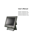
User’s Manual
X-POS950
Copyrights
©2011 All rights reserved. The information in
this document is subject to change without
prior notice in order to improve reliability,
design and function and does not represent a
commitment on the part of the manufacturer.
This document contains proprietary
information protected by copyright. All
rights are reserved. No part of this
manual may be reproduced by any
mechanical, electronic, or other means in
any form without prior written permission
of the manufacturer.
All trademarks are property of their
respective owners
Liability Disclaimer
In no event will the manufacturer be liable
for direct, indirect, special, incidental, or
consequential damages arising out of the
use or inability to use the product or
documentation, even if advised of the
possibility of such damages.
Regulatory
Information
CE mark compliance
This device complies with EMC Directive
2004/108/EC issued by the Commission of
the European Community.
Warning: This a Class B product. In a
domestic environment this product
may cause radio interference, in which
case the user may be required to take
adequate measures
Safety Statement for Lithium
Battery
I
Contents
Copyrights............................................................................................................... I
Liability Disclaimer................................................................................................. I
Regulatory Information .......................................................................................... I
CE mark compliance .................................................................................... I
Safety Statement for Lithium Battery.......................................................... I
Contents ................................................................................................................. II
1. Hardware Setup ................................................................................................. 1
1.1. Packing Contents.................................................................................. 1
1.2. Quick Tour ............................................................................................. 2
Front View and Rear View .................................................................... 2
Back Panel I/O....................................................................................... 2
1.3. Basic Peripherals Installation .............................................................. 3
Power Adapter ...................................................................................... 3
Computer Mouse and Computer Keyboard........................................ 3
USB ODD ............................................................................................... 4
LAN Cable ............................................................................................. 4
Cash Drawer.......................................................................................... 4
Customer Display ................................................................................. 4
MSR........................................................................................................ 8
2nd Display ......................................................................................... 10
1.4. Turn on the device .............................................................................. 20
2. RAID Configuration ......................................................................................... 21
2.1. For Microsoft Windows XP................................................................. 29
2.2. For Microsoft Windows Embedded POSReady................................ 32
2.3. For Microsoft Windows 7 ................................................................... 35
3. Basic Driver Installation.................................................................................. 36
3.1. Before the installation ........................................................................ 36
3.2. Chipset Software Installation ............................................................. 36
3.3. VGA Driver Installation ....................................................................... 38
3.4. Touch Screen Driver and Software Utility installation ..................... 40
3.5. LAN Driver Installation ....................................................................... 42
3.6. Audio Driver Installation..................................................................... 44
4. eGalaxy Touch Control Utility Quick Guide................................................... 45
4.1. Launch eGalaxy Touch Control Utility .............................................. 45
4.2. General ................................................................................................ 45
4.3. Settings................................................................................................ 48
4.4. Tools .................................................................................................... 51
4.5. Edge Compensation ........................................................................... 53
4.6. How to Use Event Selector ................................................................ 55
II
5. I/O Definition .................................................................................................... 56
5.1. Power Connector ................................................................................ 56
5.2. Serial Port............................................................................................ 56
5.3. Cash Drawer........................................................................................ 57
6 Specification ..................................................................................................... 58
III
1.
1. Hardware Setup
1.1. Packing Contents
1. X-POS950 X 1
4. Drive and Utility DVD X 1
2. Power Adapter X 1
5. Cable Cover X 1
3. Power Cord X 1
Chapter 1
1
1.2. Quick Tour
Front View and Rear View
LED Indicator
The Power indicator will glow green when power is on.
The HDD indicator will blink green when the HDD is accessed.
The LAN indicator will blink green when transferring data though the LAN.
Back Panel I/O
2
Chapter 1
1.3. Basic Peripherals Installation
1. All cables and wires from peripherals to the POS device are recommended to
be fed through the base in the direction as shown below.
WARNING: Before the cable cover is removed, please make sure the
power is off!
Power Adapter
Connect the DC cable to the DC in jack.
Computer Mouse and Computer Keyboard
Connect your computer mouse and keyboard to USB 1/2, UBS 3/4 or the KB/MS
port, depends on which type of computer mouse/keyboard used.
Chapter 1
3
USB ODD
Connect your USB ODD to USB 1/2 or UBS 3/4 port.
LAN Cable
Connect one end of RJ-45 LAN cable to the LAN 1 or LAN 2 port on the back
panel of the device, another end to your internet device.
Cash Drawer
Connect one end of RJ-11 cable to the Cash Drawer port on the back panel of the
device, another end to your cash drawer.
Customer Display
A. Hardware Installation
1. Remove the two screws fixing the customer display cover and then remove the
cover.
4
Chapter 1
2. Adjust the hinge of the customer display, and then connect to the device as
shown below.
3. Mount the customer display to the device and tighten the two M3 screws as
shown below.
4. Finished.
Chapter 1
5
B. Customer Display Power Supply Configuration
Caution: Never enable the power supply without the customer display installed and be
sure to disable the power supply before removing the customer display.
1. Power up the X-POS950, and press the DEL key to enter BIOS before the Windows
screen appear.
2. Under BIOS screen, use the
or
key on your computer keyboard to move to
the Advanced tab, and then use the
or
key on your computer keyboard to
select Super IO Configuration then press ENTER key.
6
Chapter 1
3. Use the
or
ENTER key.
key to highlight the Serial Port 6 Configuration, and the press
4. Use the
Use the
key to select the COM Voltage, and the press ENTER key.
key to highlight 12V and press ENTER key.
Chapter 1
or
or
7
5. Press F10 key, highlight Yes and press ENTER key.
MSR
1. Remove the two screws fixing the MSR cover.
2. Remove the MSR cover from the device.
8
Chapter 1
3. Connect the connectors of the MSR assembly to the device.
4. Tighten the two M3 screws to fix the MSR assembly as shown below.
5. Finished.
Chapter 1
9
2nd Display
Before installation, make sure that the all item listed below are ready.
Base Type 2nd Display Kit:
A.
2nd Display (12” or 15”)
F.
base bracket
B.
2nd display base
G.
M3 screw X 4
C.
2nd display support
H.
M4 screw X 2
D.
Plastic bush
I.
VGA Cable
E.
Plastic spacer
Pole Type 2nd Display Kit:
A.
2nd Display (8.4” or 10”)
G.
base bracket
B.
2nd Display Mount
H.
Plastic spacer
C.
2nd display support
I.
M3 screw X 4
D.
2nd display base
J.
M4 screw X 2
E.
Plastic pole (long)
K.
USB Cable (for USB type 2nd Display only)
F.
Plastic pole (short)
L.
VGA Cable (for VGA type 2nd Display only)
10
Chapter 1
Base Type 2nd Display Kit Installation:
1. Install the 2nd display base (item B.) onto the X-POS950 by M4 screw X 2
(Item H.) as shown.
2. Insert the plastic bush into the base as shown.
3. Feed the blue connector of the VGA cable (item I.) through the base of the device as
shown below.
4. Remove the film on the back of the plastic spacer (item E.); and then stick the
spacer to the base bracket (item F.) as shown.
Feed the blue connector of the VGA cable (item I.) through the base bracket.
Chapter 1
11
5. Connect heads of all the cables to the ports of the back I/O panel of the POS
device.
6. Feed the black head (with power connector) of the VGA cable through the 2nd
display support (item C.).
7. Connect the black head (with power connector) and the power connector of the
VGA cable to the VGA port and power input jack of the back I/O panel of the 2nd
display, and then tighten the four M3 screws to fix the 2nd display support onto
the 2nd display as shown below.
8. Insert the 2nd display onto the base of the device.
12
Chapter 1
9. Push the base holder bracket into the base, and then tighten the two M4
screws to fix the 2nd display.
10. Install the IO panel cover onto the device.
11. Finished. Now you can adjust the horizontal angle of the 2nd display.
Chapter 1
13
Pole Type 2nd Display Kit Installation:
1. Install the 2nd display base (item D.) onto the X-POS950 by M4 screw X 2
(Item I.) as shown.
2. Insert the plastic bush into the base as shown.
3. Feed the Type A USB connector of the USB cable (item K.) or the blue
connector of the VGA cable (item L.) through the base of the device as shown
below.
4. Remove the film on the back of the plastic spacer (item H.); and then stick the
spacer to the base bracket (item G.) as shown.
Feed the Type A USB connector of the USB cable (item K.) or the blue
connector of the VGA cable (item L.) through the base bracket.
14
Chapter 1
5. Connect the Type A USB connector of the USB cable (item K.) or the blue
connector of the VGA cable (item L.) to the ports of the back I/O panel of the POS
device.
6. Push the base holder bracket into the base, and then tighten the two M4
screws to fix the 2nd display.
7. Feed the Type B USB connector of the USB cable (item K.) or the black
connector of the VGA cable (with power connector) (item L.) through plastic poles
(item E. and F.) and install the plastic poles as shown below.
Chapter 1
15
8. Feed the Type B USB connector of the USB cable (item K.) or the black
connector of the VGA cable (with power connector) (item L.) through the 2nd
Display Mount (item B.).
9. Connect the Type B USB connector of the USB cable (item K.) or the black
connector of the VGA cable (with power connector) (item L.) to the proper port of
the back I/O panel of the 2nd display, and then tighten the four M3 screws to fix
the 2nd display mount onto the 2nd display as shown below.
16
Chapter 1
10. Install the 2nd display assembly as shown.
2nd Display Power Supply Configuration
1. Power up the X-POS 950, and press the DEL key to enter BIOS before the
Windows screen appear.
Chapter 1
17
2. Under BIOS screen, use the
or
key on your computer keyboard to
move to the Advanced tab, and then use the
or
key on your computer
keyboard to select Video Function Configuration then press ENTER key.
3. Use the
key.
18
or
key to highlight the VGA Power +12, and the press ENTER
Chapter 1
4. Use the
or
key to highlight Enabled and press ENTER key.
5. Press F10 key, highlight Yes and press ENTER key.
Chapter 1
19
1.4. Turn on the device
1. Make sure all peripherals are connected properly.
2. Press and hold the power switch until the power indicator on the front panel
glows green.
3. Install the cable cover.
20
Chapter 1
2.
2. RAID Configuration
RAID configuration must be done before the Windows operating system (Windows 7
excluded) installation.
Before the steps below starts, make sure that an external USB DVD-ROM drive with
the Windows installation disc loaded, an external USB floppy disc drive and other
accessories are all connected to the X-POS 950 properly.
1. On a personal computer, insert the Driver and Utility DVD into the DVD-ROM drive
and insert a 3.5” floppy into the floppy disk.
2.
On the DRIVER BANK screen, click X-POS 950 Series to enter the driver
selection screen.
3. On the driver selection screen, click SATA/ AHCI/ RAID Driver.
Chapter 2
21
4. Click AHCI/RAID Driver for DOS.
5. A Windows Explore window pops-up. There are two folders:
“RAID_F6_32bit_10.1.0.1008_PV” and “RAID_F6_64bit_10.1.0.1008_PV”.
Copy a folder into the floppy disc according to the Windows operating system you
choose to install.
6. Eject the 3.5” floppy disk and insert it into the USB floppy disk drive which is
connected to the X-POS 950.
22
Chapter 2
7. Power up the X-POS 950, and press the DEL key of the external computer
keyboard to enter BIOS before the Windows screen appear.
8. Under BIOS screen, use the
or
key on your external computer keyboard to
move to the Advanced tab, and then use the
or
key on your computer
keyboard to highlight SATA Configuration and then press the ENTER key.
Chapter 2
23
9. Under Advance tab, highlight SATA Mode and then press the ENTER key of the
external computer keyboard.
10. Select RAID Mode or AHCI Mode according to your application, and then press the
ENTER key of the external computer keyboard.
24
Chapter 2
11. Press the F10 key of the external computer keyboard, select Yes and then press
the ENTER key of the external computer keyboard.
12. The screen below shows, press the CTRL key and I key of the external computer
keyboard simultaneously.
Chapter 2
25
13. Under the MAIN MENU, select Create RAID Volume and then press ENTER key of
the external computer keyboard.
14. Under the CREATE VOLUME MENU, highlight the item Name to specify the
volume name.
26
Chapter 2
15. Highlight the item RAID Level to specify the RAID type (RAID0 or RAID1).
16. Back to the MAIN MENU, select EXIT and then press ENTER key of the external
computer keyboard.
Chapter 2
27
17. Press Y key of the external computer keyboard and then press F11 key to enable
the system to reboot by external optical disk drive.
18. The screen below shows and then switches to the Windows installation
automatically.
Steps below are variable based on the OS you had chosen.
28
Chapter 2
2.1. For Microsoft Windows XP
Steps described below are for Microsoft Windows XP series.
1.
Press the F6 key of the external computer keyboard as soon as the message on
the gray bar shows.
2.
Press S key.
Chapter 2
29
3.
If “RAID Mode” is selected under the SATA Configuration in BIOS:
Use the
or
key to select Intel (R) Desktop/Workstation/Server Express
Chipset SATA RAID Controller.
If “AHCI Mode” is selected under the SATA Configuration in BIOS:
Use the
or
key to select Intel (R) Desktop/Workstation/Server Express
Chipset SATA AHCI Controller.
30
Chapter 2
4.
Press S key to continue.
5.
Setup is loading files.
Chapter 2
31
6.
7.
Repeat Step 2, Step 3 and Step 4.
Press ENTER key to continue Windows XP installation.
2.2. For Microsoft Windows Embedded POSReady
Steps described below are for Microsoft Windows Embedded POSReady series.
1. When the message on the gray bar shows, press the F6 key of the external
computer keyboard.
32
Chapter 2
2. Press ENTER key.
3.
If “RAID Mode” is selected under the SATA Configuration in BIOS:
Use the
or
key to select Intel (R) Desktop/Workstation/Server Express
Chipset SATA RAID Controller.
Chapter 2
33
If “AHCI Mode” is selected under the SATA Configuration in BIOS:
Use the
or
key to select Intel (R) Desktop/Workstation/Server Express
Chipset SATA AHCI Controller.
4. Press ENTER key to continue.
34
Chapter 2
5. On the screen below, select Install Third-Party Storage Drivers.
Click Next to continue rest steps of Microsoft Windows Embedded POSReady
installation.
2.3. For Microsoft Windows 7
There is not any special configuration or setting for RAID during Microsoft Windows 7
installation.
Chapter 2
35
3.
3. Basic Driver Installation
3.1. Before the installation
1. Connect an external USB CDROM to the USB port and insert the
Driver and Utility DVD and turn on the device. The program autoruns
and displays the DRIVER BANK screen.
2. On the DRIVER BANK screen, click XPOS 950 Series to enter the
driver selection screen.
3.2. Chipset Software Installation
1. On the driver selection screen, click INTEL Chipset Driver.
36
Chapter 3
2. Click Next.
3. Read the License Agreement carefully and click Yes.
4. Click Next.
5. Click Finish.
Chapter 3
37
3.3. VGA Driver Installation
1. On the driver selection screen, click VGA Driver.
2. Click VGA Driver for Windows XP.
3. Click Next.
4. Read the License Agreement carefully and click Yes.
38
Chapter 3
5. Click Next.
6. Click Next.
7. Select restart your computer right now or later, and then lick Finish.
Chapter 3
39
3.4. Touch Screen Driver and Software Utility
installation
1. On the driver selection screen, click Touch Panel Driver.
2. Click Touch Panel Driver For Windows.
3. Click Next.
40
Chapter 3
4. The Install RS232 interface driver box is checked as default, click
Next.
5. Click the OK button on the message box.
6. Check any box according to your needs, and then click OK.
7. The driver and program will be installed automatically.
Chapter 3
41
8. Select an item according to your needs, and then click Next.
3.5. LAN Driver Installation
1. On the driver selection screen, click LAN Drive.
2. Click RTL8111C Driver For XP.
3. Click Next.
42
Chapter 3
4. Click Next.
5. The driver will be installed automatically.
6. Click Finish.
Chapter 3
43
3.6. Audio Driver Installation
1. On the driver selection screen, click HD Audio Driver.
2. Click Next.
3. The driver and program will be installed automatically.
4. Select an item according to your needs, and then click Next.
44
Chapter 3
4.
4. eGalaxy Touch Control Utility Quick
Guide
4.1. Launch eGalaxy Touch Control Utility
Under Microsoft Windows Embeded, click “Start” menu and select
“All Programs”, under ”eGalaxy Touch” menu, click “TouchMon”.
4.2. General
The General tab in eGalaxy Touch shows all of TouchMon
touchscreen controllers installed as below, including RS232, USB
and PS2 interfaces.
Chapter 4
45
Add
The function button is used for serial RS232 controllers only.
Press this button to search the TouchMon serial controllers
connected with the COM ports of the device. Whenever it finds
a new TouchMon serial controller, a new serial controller icon
object will be shown in the controller list window automatically.
USB TouchMon device supports plug and play, the icon object
for USB controller will be shown in the controller list window
automatically when the USB controller is connected with the
USB port of the device. And, the icon object for the USB
controller will disappear automatically as soon as the device
was removed from the USB port of the device.
TouchMon PS2 driver support PS2 mouse and TouchMon
touchscreen controller. It can works with both PS2 mouse and
TouchMon touchscreen PS2 controller. After the TouchMon
PS2 driver was installed, this utility assumes the PS2
touchscreen controller exists and is always shown in the
controller list window.
Remove
This function button is used for serial RS232 controllers only.
This button will be grayed and disabled automatically when the
selected controller in the controller list window is not RS232
type. Press to remove and uninstall the selected serial RS232
controller from the device. Then, this serial RS232 icon object
in controller list window disappears automatically.
USB TouchMon device supports plug and play, the icon object
for USB controller will be shown in the controller list window
automatically when the USB controller is connected with the
USB port of the device. And, the icon object for the USB
controller will disappear automatically as soon as the device
was removed from the system USB port.
46
Chapter 4
TouchMon does not allow you to remove/uninstall the PS2
device driver dynamically. To uninstall the TouchMon PS2
driver, you need to go to Windows Device Manager to do
un-installation. In addition, after PS2 un-installation, it needs to
reboot the device to complete un-installation.
Monitor Mapping
This function is to define the primary touchscreen display when
external touchscreen display is connected.
The first touchscreen display (including the onboard 15”
touchscreen) where you run this function first will be set as the
primary one.
On the touchscreen display you want to set as the primary,
launch the eGalaxy Touch and click the Monitor Mapping
button under the General tab.
The screen below will show, the character “1” means “primary”
(“2” means secondary, and so on).
Touch the yellow box to switch back to the General tab.
Chapter 4
47
4.3. Settings
There are function buttons and check boxes in the Settings tab.
Beep
Beep On Touch
Check this check box to enable driver to generate a beep
sound when touchscreen state is switched from untouched to
touched state.
Beep On Release
Check this check box to enable driver to generate a beep
sound when touchecreen state is switched from touched state
to untouched state.
Beep From System Beep
Check this check box to enable driver to generate a beep
sound from the operation system.
Beep From Sound Card
Check this check box to enable driver to generate a beep
sound from the sound card onboard.
48
Chapter 4
Frequency
Drag the slider to adjust this frequency to control the beep
sound frequency generated by the driver.
Duration
Drag the slider to adjust this duration to control the beep sound
duration.
Linearization Style
TouchMon provides you with both 9 points and 25 points
calibration for linearization. You can select the suitable
linearization type.
Double Click Time
Double Click Time is used to set double click time. Change
this value will affects the double click behavior for all of the
mouse devices connected to the device. Two continuous clicks
at the same area within this specified time period will be
recognized as a double click event.
Double Click Area
Double click area is used to set the double click area. Change
this value will affects the double click behavior for all of the
mouse devices connected to the device. Two continuous clicks
with this specified area in the specified double click time will be
recognized as a double click event.
Click On Touch
Change the emulation mode by pressing on this button.
Chapter 4
49
Normal Mode
Normal mode behaves mouse button down and mouse move.
You can select this mode to select object, and dragging the
object.
Click On Touch
With this Click On Touch mode, the driver emulates a mouse
click event when the touchscreen state was switched from
un-touched state to touched state. Then, the driver always
generate mouse move event and is tracking the touch position
until the touchscreen state switched to un-touch state.
Click On Release
With this Click On Release mode, the driver emulates a
mouse click event when the touchscreen state was switched
from touched state to un-touched state.
Click On Touch without moving cursor
With this mode, the driver behaves similar as Click On Touch
mode. The cursor does not move to the touch position except
the first touch point.
Click On Release without moving cursor
With this mode, the driver behaves similar as Click On
Release mode. The cursor does not move to the touch
position except the lift-off point.
50
Chapter 4
Option
You can set configuration for some advanced functions with
this option button. Press this button, a pop up property sheet
window will be popped up and shown as below.
4.4. Tools
There are function buttons and check boxes in the Tools tab.
Chapter 4
51
4 Points Calibration, Clear and Calibration, and
Iinearization button
Click the one of three these buttons and follow the instruction
on the screen to do the screen calibration.
Draw Test
After clicking this button, you can do the drawing test by
drawing any path on the screen as shown below.
You can remove all paths you drew by clicking Clear, or exit
this screen by clicking Quit.
52
Chapter 4
4.5. Edge Compensation
Edge Compensation property page contains functions of
Edge Compensation for Top, Bottom, Left, Right, X Axis
and Y Axis.
In some cases, if it is difficult to touch items at the edges of
the touch panel, you can set adjustment to reach the edges
of the screen image.
Top
If you set the Edge to "Smaller", TouchMon will reduce the
horizontal position of the top edge. If you set the Edge to
"Larger", TouchMon will extend the horizontal position of
the top edge.
Bottom
If you set the Edge to "Smaller", TouchMon will reduce the
horizontal position of the bottom edge. If you set the Edge to
"Larger", TouchMon will extend the horizontal position of
the bottom edge.
Left
If you set the Edge to "Smaller", TouchMon will reduce the
vertical position of the right edge. If you set the Edge to
Chapter 4
53
"Larger", TouchMon will extend the vertical position of the
left edge.
Right
If you set the Edge to "Smaller", TouchMon will reduce the
vertical position of the right edge. If you set the Edge to
"Larger", TouchMon will extend the vertical position of the
right edge.
In some cases, cursor will be behind the finger when you
touch the panel. If you can not see the cursor when you
touch down the panel, you can set X Axis or Y Axis to move
the cursor.
Offset X Axis
If you set the Offset X Axis to Smaller, cursor will be moved a
pixel of X Axis to left.
If you set the Offset X Axis to Larger, cursor will be moved a
pixel of X Axis to right.
Offset Y Axis
If you set the Offset Y Axis to Smaller, cursor will be moved a
pixel of Y Axis to top.
If you set the Offset Y Axis to Larger, cursor will be moved a
pixel of X Axis to bottom.
Edge Compensation Switch
You can check Support Edge Compensation check box to
enable/disable this function from left corner.
Edge Compensation Button
Click +10% or -10% button to adjust the smaller or larger of
edge.
54
Chapter 4
If you click +10% button, the top, bottom, left and right edges
will extend 10% of orientation to touch screen, and cursor
will be moved 10 pixel of X and Y Axis to right and top.
If you click -10% button, the top, bottom , left and right edges
will contract 10% of orientation to touch screen, and cursor
will be moved 10 pixel of X and Y Axis to left and bottom.
Click Default button to resume to the default value.
4.6. How to Use Event Selector
For launching the event selector, right click on the eGalaxy
icon
on the task bar, and then select Display Button
command.
1. On the desktop of Windows, click
2.
icon change to
icon.
.
3. Now the tapping is simulating right mouse button clicking.
4. After one tap on the screen,
icon change to
.
5. The tapping resumes to left mouse button clicking.
Chapter 4
55
5.
5. I/O Definition
Please refer the detailed technical information about all I/O ports as followings.
5.1. Power Connector
PIN
Description
PIN
Description
1
+19V
3
GROUND
2
+19V
4
GROUND
5.2. Serial Port
COM Port
PIN
Description
PIN
Description
1
DCD
6
DSR
2
RXD
7
RTS
3
TXD
8
CTS
4
DTR
9
RI / 5V /12V
5
GND
PIN
R232
RS422
RS485
1
DCD
TX-
D-
2
RXD
TX+
D+
3
TXD
RX+
4
DTR
RX-
Chapter 5
56
5.3. Cash Drawer
Connector
PIN
Description
PIN
Description
1
GND
4
P24V
2
D_OUT0
5
N/C
3
D_IN
6
GND
Cash Drawer Control
Status
Address
Value
Open
280H
Bit 4 = 0
Close
280H
Bit 4 = 1
280H
Bit 0 = 0/1
Read Status
57
Chapter 5
6.
6 Specification
Chapter 5
58
Main Board
Chipset
Intel® Sandy Bridge LGA1155
Core i7 - 2600 3.4 GHz (TB 3.8GHz) / L3: 8MB / 4 core 8 threads / 95 watt
Core i5 - 2400 3.1 GHz (TB 3.4GHz) / L3: 6MB / 4 core 4 threads / 95 watt
Core i3 - 2120 3.3 GHz / L3: 3MB / 2 core 4 threads / 65 watt
Pentium G850 2.9 GHz / L3: 3MB / 2 core 2 threads / 65 watt
Intel® BD82Q67 PCH
System Memory
2xDIMM, supported DDR3 1066/1333. up to 8GB per channel
OS
Windows® XP / WES, POSReady 2009, Windows 7
CPU
Display
TFT LCD Size
15”
Brightness
250 nits , brightness adjustment by BIOS
Resolution
1024 x 768
Touch Screen
5-wire Resistive Type
Tilt Angle
0°~90°
Storage Device
HDD
Compact Flash
2 x 2.5" Removable HDD Drive Bay , Support RAID 0, 1 function
1 x CFast slot
I/O Ports
VGA
USB
LAN
5 x RS-232
COM 1 : RS-232/422/485, DB-9, Pin9 w/ RI/5V/12V
Selectable by BIOS
COM 2 / 5 : DB-9, Pin9 w/ RI/5V/12V Selectable by BIOS
COM 3 : RS232, internal pin header for MSR
COM 6 : RS232, internal pin header for Customer Display
1 x DB15, Supported DC12V/1A output.
6 x USB 2.0 (4 x external, 2 x internal)
2 x Gigabit Ethernet by RJ-45 , Support Wake on LAN
Cash Drawer
1 x RJ-11 (24 VDC)
PS/2 Keyboard / Mouse
1 x Mini-DIN
Parallel
1 x DB25
Serial
Others
Wall mount
Support VESA Mount 75x75 / 100x100mm
Power Input
External adapter,180Watt, 19VDC input
Color
Material
Black
Plastic / Aluminum
EMC& Safety Compliance
FCC / CE / WEEE / RoHS / VCCI
Front Panel Protection
IP 65 compliance
Weight
7.95 Kg (appox.)
Dimension
380W x 260D x 315H (mm)
Operation Temperature
0°C ~ 40°C
Storage Temperature
-20°C ~ 60°C
Storage Humidity
20% - 90% RH, non-condensing
Audio
1.5W Speaker X 1
Chapter 6
59
Optional Accessories
Customer display: VFD Attached, 20 columns x 2 lines, RS-232 Type
MSR-Front Type, 3 Tracks, PS/2 Type
MSR-Side Type, 3 Tracks, PS/2 Type & Finger Print, USB Type
MSR-Side Type, 3 Tracks, PS/2 Type & i-Button, PS/2 Type
12.1” 2nd Display
Specifications are subject to change without notice.
Chapter 5
60