1
Lab-LINKTM for Windows
Part 1
Lab-LINK for Windows
User’s Manual
Top Team Technology, Inc.
Table of Contents
Chapter 1 Intstalltion
System Requirement____________________________________________________ 1-1
Installation ____________________________________________________________ 1-1
Software protection _____________________________________________________ 1-3
Chapter 2 PAM
Start PAM ____________________________________________________________ 2-1
Project Configuration Procedure ___________________________________________ 2-2
Menu ________________________________________________________________ 2-3
Project ______________________________________________________________ 2-3
New............................................................................................................................ 2-4
Open .......................................................................................................................... 2-6
Save........................................................................................................................... 2-7
Save As...................................................................................................................... 2-7
Close.......................................................................................................................... 2-8
Delete ........................................................................................................................ 2-8
Project Info ................................................................................................................ 2-9
Exit ........................................................................................................................... 2-12
View _______________________________________________________________ 2-13
Run ________________________________________________________________ 2-14
Generate .................................................................................................................. 2-14
Run Project .............................................................................................................. 2-15
Stop Project ............................................................................................................. 2-16
Tool ________________________________________________________________ 2-16
Help ________________________________________________________________ 2-17
Toolbar______________________________________________________________ 2-18
Module Page in Project Window __________________________________________ 2-18
TAG Database ........................................................................................................... 2-19
Alarm ....................................................................................................................... 2-19
Data ......................................................................................................................... 2-20
Report ...................................................................................................................... 2-20
DDE Connection ...................................................................................................... 2-20
Network Connection ................................................................................................ 2-21
IO Driver .................................................................................................................. 2-21
OPC Connection ...................................................................................................... 2-21
Script........................................................................................................................ 2-21
Project Files and Folders _______________________________________________ 2-21
File Page in Project Window _____________________________________________ 2-22
File Operation .......................................................................................................... 2-22
Management of Other Files ..................................................................................... 2-25
Script Files ............................................................................................................... 2-25
Chapter 3 Workstation
Workstation ___________________________________________________________ 3-1
Basic Setting of Workstation ______________________________________________ 3-2
Identification .............................................................................................................. 3-2
Security ...................................................................................................................... 3-3
Execution ................................................................................................................... 3-4
Advanced ................................................................................................................... 3-4
Add Workstation _______________________________________________________ 3-5
Copy Workstation ______________________________________________________ 3-6
Delete Workstation _____________________________________________________ 3-6
Rename ______________________________________________________________ 3-7
Chapter 4 TAG
Tag__________________________________________________________________ 4-1
Tag Manager __________________________________________________________ 4-1
Tag Naming Rule _______________________________________________________ 4-1
Tag Data Structure _____________________________________________________ 4-2
Tag Manager Dialog ____________________________________________________ 4-3
System Tag ___________________________________________________________ 4-4
Add Tag ______________________________________________________________ 4-4
DeleteTag ____________________________________________________________ 4-5
Rename Tag __________________________________________________________ 4-6
Tag Basic Setting ______________________________________________________ 4-7
Tag Admin ____________________________________________________________ 4-8
Chapter 5
Introduction ___________________________________________________________ 5-1
Features _____________________________________________________________ 5-1
Architecure ___________________________________________________________ 5-2
Alarm Processing ______________________________________________________ 5-2
Alarm Logging _________________________________________________________ 5-2
Alarm Log Format ______________________________________________________ 5-3
Alarm Types __________________________________________________________ 5-4
Expand and Collapse of Alarm Node _______________________________________ 5-5
Basic Setting __________________________________________________________ 5-5
Alarm Log Option ....................................................................................................... 5-6
Alarm Printer .............................................................................................................. 5-6
Alarm Log Path .......................................................................................................... 5-7
Disable Alarm _________________________________________________________ 5-8
Alarm Properties Setting _________________________________________________ 5-9
Digital Alarm Setting ___________________________________________________ 5-10
High/Low Alarm Setting _________________________________________________ 5-15
HH/H/L/LL Alarm Setting ________________________________________________ 5-22
Rate of Change Alarm Setting ___________________________________________ 5-30
DeviationAlarm Setting _________________________________________________ 5-36
Timeout Alarm Setting __________________________________________________ 5-43
Trip Alarm Setting _____________________________________________________ 5-49
Event Alarm Setting____________________________________________________ 5-55
Alarm Related System TagSetting ________________________________________ 5-61
Chapter 6 Data
Introduction ___________________________________________________________ 6-1
Features _____________________________________________________________ 6-1
Expand and Collapse of Data Node ________________________________________ 6-2
Add Data Group _______________________________________________________ 6-2
Basic Setting __________________________________________________________ 6-3
Interval ....................................................................................................................... 6-3
File Name Prefix ........................................................................................................ 6-4
File Type (Data File Format) ...................................................................................... 6-4
Data File Path ............................................................................................................ 6-5
Data File Expiration ................................................................................................... 6-6
Data Group Setting _____________________________________________________ 6-8
Tag ............................................................................................................................. 6-9
Data Group ................................................................................................................ 6-9
Aggregation ............................................................................................................... 6-9
Output Tag ............................................................................................................... 6-10
Gain and Offset........................................................................................................ 6-10
Remark .................................................................................................................... 6-10
Action ....................................................................................................................... 6-11
Delete ...................................................................................................................... 6-11
Delete a Data Group ___________________________________________________ 6-12
Rename a Data Group _________________________________________________ 6-12
Disable _____________________________________________________________ 6-13
Chapter 7 Report
Introduction ___________________________________________________________ 7-1
Features _____________________________________________________________ 7-1
Report Types __________________________________________________________ 7-2
Add a Text Report ______________________________________________________ 7-2
Basic Setting of Text Report ______________________________________________ 7-3
Text Report Setting _____________________________________________________ 7-6
Add a Trend Report _____________________________________________________ 7-9
Basic Setting of Trend Report _____________________________________________ 7-9
Trend Report Setting ___________________________________________________ 7-12
Delete a Report _______________________________________________________ 7-14
Adjust Report Order
__________________________________________________ 7-15
Running the Report Module _____________________________________________ 7-16
Command Parameters of Report Module ___________________________________ 7-18
Runtime Report Operation ______________________________________________ 7-19
Select a Report ........................................................................................................ 7-19
Select a Date ........................................................................................................... 7-20
Preview and Print .................................................................................................... 7-21
Exit Report ............................................................................................................... 7-22
Chapter 8 DDE Connection
Introduction ___________________________________________________________ 8-1
Features _____________________________________________________________ 8-1
DDE Connection Format _________________________________________________ 8-1
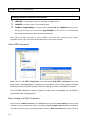
Add a DDE Connection __________________________________________________ 8-2
Basic Setting of a DDE Connection ________________________________________ 8-2
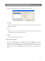
DDE Connection Setting _________________________________________________ 8-3
Delete a DDE Connection ________________________________________________ 8-5
DDE Server Application__________________________________________________ 8-6
Chapter 9 Network Connection
Introduction ___________________________________________________________ 9-1
Features _____________________________________________________________ 9-1
Architecture ___________________________________________________________ 9-1
Basic Setting of ServerWorkstation_________________________________________ 9-2
Activate Network Server _________________________________________________ 9-3
Add a Network Connection _______________________________________________ 9-4
Basic Setting of Network Connection _______________________________________ 9-5
Network Connection Setting ______________________________________________ 9-7
Delete a Network Connection ____________________________________________ 9-10
Detecting Disconnection ________________________________________________ 9-10
Recovery of Network Connection _________________________________________ 9-10
Chapter 10 IO Driver
Introduction __________________________________________________________ 10-1
Add an IO Driver ______________________________________________________ 10-1
Basic Setting of an IO Driver _____________________________________________ 10-2
Basic Setting – Serial Interface ............................................................................... 10-3
Basic Setting – Ethernet Interface ........................................................................... 10-5
Basic Setting – Optional .......................................................................................... 10-6
Basic Setting - Device ............................................................................................. 10-8
IO Tag Setting _______________________________________________________ 10-11
Reference __________________________________________________________ 10-27
Delete IO Driver _____________________________________________________ 10-29
Delete IO Driver _____________________________________________________ 10-29
Disable IO Driver _____________________________________________________ 10-30
Detection of Communication Problems ____________________________________ 10-30
Suspend Communication ______________________________________________ 10-31
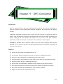
Chapter 11 OPC Connection
Introduction __________________________________________________________ 11-1
Features ____________________________________________________________ 11-1
OPC Architecture _____________________________________________________ 11-2
Add an OPC Connection ________________________________________________ 11-3
Add OPC Server ______________________________________________________ 11-4
Add OPC Group ______________________________________________________ 11-6
Add OPC Item ________________________________________________________ 11-8
Delete OPC Item _____________________________________________________ 11-11
Delete OPC Group ___________________________________________________ 11-11
Delete OPC Serer ____________________________________________________ 11-12
Modify OPC Group Settnig _____________________________________________ 11-13
Modify OPC Item Setting_______________________________________________ 11-14
Chapter 12 Script
Script File and Module _________________________________________________ 12-1
Add Script Module _____________________________________________________ 12-2
Create a New Script ................................................................................................ 12-3
Reference to an Existing Script ............................................................................... 12-3
Edit Script ___________________________________________________________ 12-4
Delete Script Module ___________________________________________________ 12-5
Disable Script ________________________________________________________ 12-5
Chapter 13 Security
Introduction __________________________________________________________ 13-1
Login and Logout _____________________________________________________ 13-1
Automatic Logout _____________________________________________________ 13-2
System Tags Related to Security _________________________________________ 13-3
User Setting _________________________________________________________ 13-3
Run Security Editor ____________________________________________________ 13-4
Display User Setting ___________________________________________________ 13-5
Edit User Data ________________________________________________________ 13-5
Add User ____________________________________________________________ 13-6
Delete User __________________________________________________________ 13-7
Limitation on Use of Security Editor _______________________________________ 13-7
Exit Security Editor and Save Setting ______________________________________ 13-8
Option Setting ________________________________________________________ 13-9
Security Setting File __________________________________________________ 13-10
Use Windows Authentication ___________________________________________ 13-11
Winsows Group Setting________________________________________________ 13-12
Chapter 14 Tag View
Introduction __________________________________________________________ 14-1
Features ____________________________________________________________ 14-1
Run Tag View ________________________________________________________ 14-1
Tagview Window ______________________________________________________ 14-2
Tag List _____________________________________________________________ 14-2
Tag Data ____________________________________________________________ 14-3
Show Tag Data _______________________________________________________ 14-4
Write Tag Data________________________________________________________ 14-4
Isolation _____________________________________________________________ 14-5
Fix Tag View Window on top _____________________________________________ 14-6
Exit Tag View _________________________________________________________ 14-7
Chapter 15 Deployment
Introduction __________________________________________________________ 15-1
Single Machine Project _________________________________________________ 15-1
Network Project _______________________________________________________ 15-2
Read Only Setting _____________________________________________________ 15-3
Chapter 1
Installation
System Requirement
System Requirement
CPU: Pentium Ⅲ 800 MHz, Pentium4 2.4GHz or above recommended
RAM: 128MB, 256 MB or above recommended
Hard Disk: 200MB or more available hard disk space
CD-ROM
SVGA Display card and Color Monitor
Mouse and Keyboard
Operating System: Windows 2000/XP
Installation
1-1
Lab-LINK for Windows User Manual
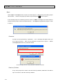
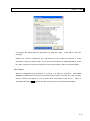
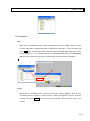
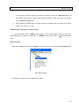
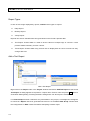
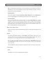
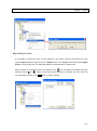
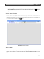
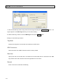
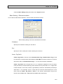
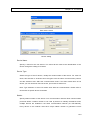
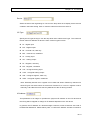
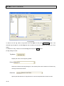
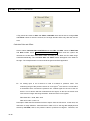
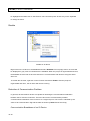
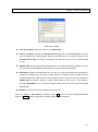
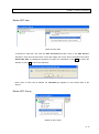
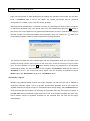
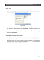
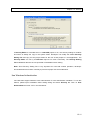
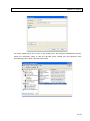
Please insert Lab-LINK for Windows CD-ROM into CD-ROM drive.
The installation screen
should appear:
Install Lab-LINK 4.0: Install the main system of Lab-LINK for Windows Scada Package
Install Lab-LINK 4.0 Add-on Modules: Install additional add-on modules:
Install DBSaver: Install DBSaver Database Tool to provide commercial database data
saving capability.
Install DBReport: Install DBReport, a database report tool.
Install SmartRecipe: Install SmartRecipe, a recipe access tool.
Install Notifier: Install Notifier, a tool to send voice message through telephone.
Select “Install Lab-LINK for Windows 4.0” to install the main package.
finish the installation.
Follow the instructions to
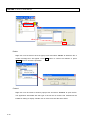
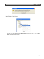
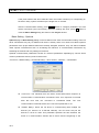
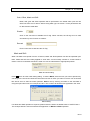
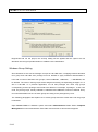
When the installation is completed, a Lab-LINK for Windows 4” folder will
be created in the All Program List in Start Menu.
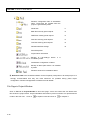
The following shortcut will also be added into
the folder:
SmartPAM: The integrated Development Environment(IDE) of Lab-LINK.
Security Editor: The user management tool of Lab-LINK.
TagView: The Test and Debug Tool of Lab-LINK.
Help: Lab-LINK documentation.
Demo: A Lab-LINK demo project runtime shorcut.
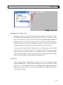
Software protection
1-2
Chapter 1 Installation
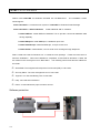
All Lab-LINK for Windows products come with a software protection dongle (keypro).
The
dongle must be properly connected to the parallel port or USB port of your computer for Lab -LINK
to execute normally.
Lab-LINK will be in evaluation mode when the dongle is not detected.
Under evaluation mode, Lab-LINK has the following limits:
Execution of Lab-LINK runtime will end in 60 minutes.
The number of IO Tag cannot exceed 48.
The panel file created by Panel Editor will be save a special format that is not compatible
with those used by a licensed edition Lab-LINK.
1-3
Chapter 2
PAM
PAM is the Integrated Development Environment (IDE) of Lab-LINK.
It is used to develop a
Lab-LINK project and the configuration of each Lab-LINK modules used in this project.
Start PAM
After the installation of Lab-LINK, select “Start\All Program\Lab-LINK 4 for Windows\PAM” to run
PAM and begin the development of a project.
PAM
2-1
Lab-LINK for Windows User Manual
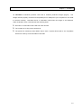
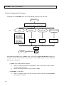
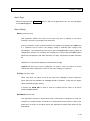
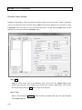
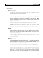
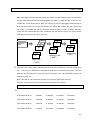
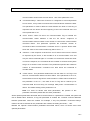
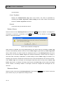
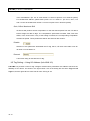
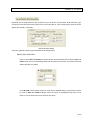
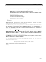
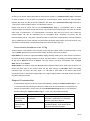
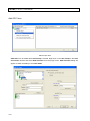
Project Configuration Procedure
Configuration of a Lab-LINK project can be summarized as shown in the flow chart:
New Project
1.
2.
Tools:
New Project Wizard
Auto creation of project and its folder
PAM
PanelEdit
1. Tag Setting
2. Alarm Setting
3. Data Setting
4. Report Setting
5. IO Driver Setting
6. DDE Setting
7. OPC Setting
8. Network Setting
Security Editor
Panel
Editing
User
Setting
SmartScript Editor
SmartScript
programming
Generate
Test
TagView
Run
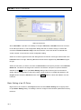
Select New from Project menu in PAM to open a new project, New Project Wizard will guide you
through the creation of the structure of a new project. Tools in PAM can then be used to configure
detail setting of the project:
(1) PAM – Project Administration Manager
Used to configure Workstation, Tag database, Alarm, Data, Report, DDE, Network,
I/O Driver, OPC and Script.
Please read related chapters in this manual for details.
(2) PanelEdit – Panel Editor
Used to configure panels, the user interface screens. Please read “SmartPanel
User Manual” for details.
2-2
Chapter 2 PAM
(3) Security Editor
(4)
Used to define users. Please read Security chapter for details.
SmartScript Editor
Used to edit SmartScript. Please read “SmartScript Reference Manual” for
details.
(5)
Generate and run the project
A project must be generated to create the runtime configuration files used by
Lab-LINK runtime system to run the project.
Modification on any module requires regeneration of the project for the change to
take effect in Lab-LINK runtime system.
Panel file or graphic file modification
doesn’t need regeneration of project.
Run project to test it.
TagView can be used to monitor the value of each Tag.
Please read chapter 14 for
the use of TagView.
Menu
PAM has these Menus: Project, View, Run, Tool and Help to provide corresponding functions.
Project Menu
New ─ Create a new project.
Open – Open an existed project.
2-3
Lab-LINK for Windows User Manual
Save – Save a modified project.
Save as – Save the modified project to a new project with different name.
Close – Close the current opened project.
Delete- Delete one or more projects.
Import – Import an existed project and save it as a different name. Usually to upgrade a
project with previous version of PAM
Project Info – To show and edit project related information.
Latest project – The names of the last four projects that have been open lately is shown.
An easy way to select and open these projects.
Exit – End the execution of PAM.
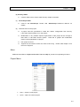
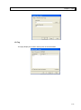
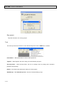
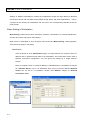
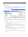
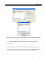
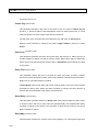
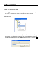
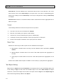
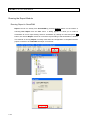
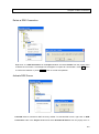
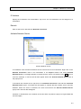
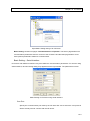
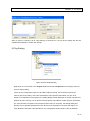
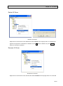
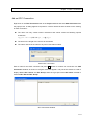
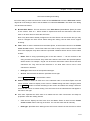
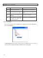
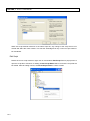
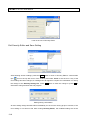
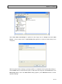
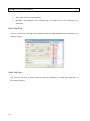
New
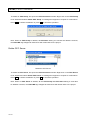
Select New to create a new project.
New Project Wizard will appear to guide you through the
procedures.
New Project Wizard (1)
New Project Wizard (1) ─ Enter project name
Page 1 of New Project Wizard of will request for a new project name. The name will also
be use to created the project folder under \lablink\project. All files related to the project
should be store under the project folder.
2-4
Chapter 2 PAM
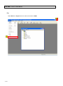
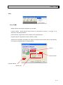
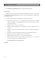
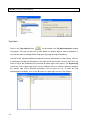
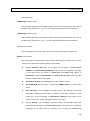
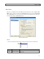
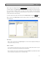
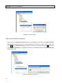
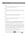
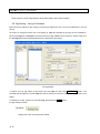
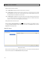
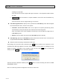
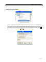
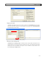
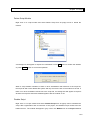
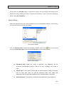
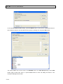
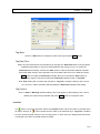
Press Next button to enter page 2 of New Project Wizard.
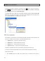
New Project Wizard (2)
Page 2 of New Project Wizard of will request for new workstation names. A project can
contain one or more workstations. Each workstation can have separate configuration for
their panels, alarm, data, report…functions.
New Project Wizard (1) ─ Enter workstation name
Press Add button after entering workstation name in New Workstation field and the name is shown
in the box below. Add all the workstation as needed and press Finish button to close the wizard. A
root panel file with the same name as the workstation will be created in pnl subfolder under the
project folder for each workstation.
2-5
Lab-LINK for Windows User Manual
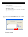
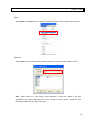
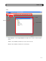
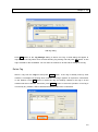
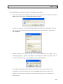
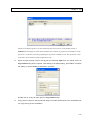
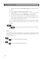
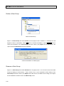
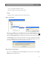
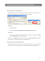
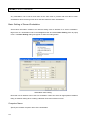
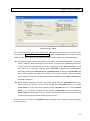
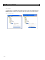
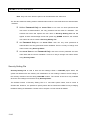
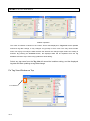
Open
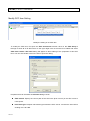
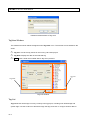
Select Open from Project menu to open an existed project. A dialog listing all existing project
will be shown.
Click on the project you wish to open and press OK button to open it.
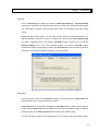
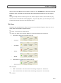
If the selected project is created by previous version of PAM, a message box will be shown to
indicate that the project cannot be opened directly.
Use Import to upgrade the project in order
to open it.
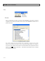
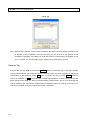
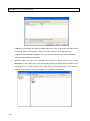
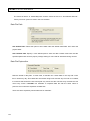
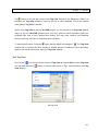
Password
A project can be protected by a password.
try to open the project.
If so, a message will appear when you
Enter correct password and press OK to open it.
Please
see Project Info section for password details.
Error message shown if the password entered is incorrect
Read-only Problem
If any of the project file or folder is set with read-only attribute, PAM will not be able to
open it. Be sure to clear the read-only attribute.
2-6
Chapter 2 PAM
Save
Select Save from Project menu to save the change you made to the currently opened project.
Save as
Select Save as to save the currently opened project to a new project with a different name.
Note : When saved as a new project, object definition in panel files related to file path
designation may need modification due to the change of project folder.
Reference path
described in Appendix can help on this issue.
2-7
Lab-LINK for Windows User Manual
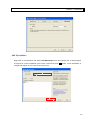
Close
Choose Close from Project menu to close the opened project. Remember to save the project
before closing. Closing a project without saving it may cause the lost of all modification made to
it. A message will appear to remind user about this.
Save project confirmation
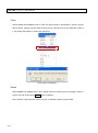
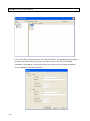
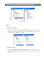
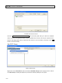
Delete
Select Delete from Project menu and a dialog listing all existing project will appear. Select a
project from the list and press Delete button to delete it.
Note: Delete a project will also remove any file or subfolder under its project folder
2-8
Chapter 2 PAM
A project in used or opened cannot be deleted and will be shown in gray color.
Import
Select Import from Project menu to upgrade a project to current Lab-LINK version.
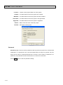
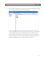
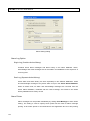
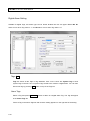
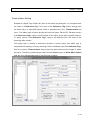
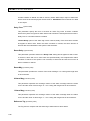
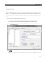
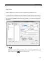
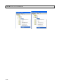
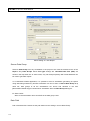
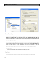
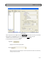
Project Info
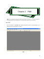
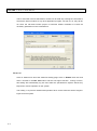
Select Project Info from Project menu to show the Project Info Dialog. There are three pages in
the dialog: Basic, Password and I/O Tag.
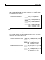
Basic
Click on Basic Tab to show the basic information of the project:
2-9
Lab-LINK for Windows User Manual
Location: Location of the project folder in the file system
Created: The date and time when the project was created.
Modified: The date and time when the project was last modified.
Generated: The date and time when the project is last generated.
Upgraded: The date and time when the project is upgraded.
Autoho: Name of the user who create the project.
Remark: Description of the project.
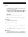
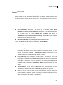
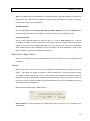
Password
Password page is used to set the password used to protect the project from unauthorized
modification. If a password is set, it will be needed when the project is opened. Any text
string can be used as a password and there is no limit on the number of characters in a
password. The password must be entered twice to confirm its correctness.
Press Clear button to clear the password setting.
2-10
Chapter 2 PAM
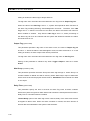
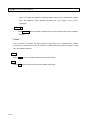
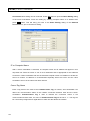
I/O Tag
This page display the number used by each of the workstation.
2-11
Lab-LINK for Windows User Manual
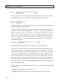
Exit
Select Exit from Project menu to end the execution of PAM.
2-12
Chapter 2 PAM
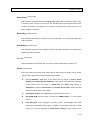
View
Toolbar
Refresh
Project window
Project Window ─ Select Project Window from View menu to show or hide the project
window.
Toolbar ─ Select Toolbar from View menu to show or hide the tool bar.
Refresh ─Select Toolbar from View menu to refresh display.
2-13
Lab-LINK for Windows User Manual
Run
Generate
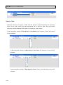
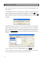
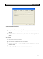
After the configuration of a project, you should conduct Generate on the project to create the
configuration files needed by Lab-LINK runtime system. Select Generate from Run menu to
generate the project.
Only module changed since last generation will be regenerate to speed up the pro cess.
However, you can select the module you want to regenerate disregard whether it is changed or
not by click on the checkbox of that module. All checked module will be regenerated. After the
selection, press OK to start the generation.
are checked and regenerated.
2-14
Select All and press OK will cause all modules
Chapter 2 PAM
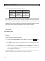
A message will appear after the generation to show the result.
Press OK to close the
message.
Besides the runtime configuration files, generation will also create the shortcut for each
workstation under the project folder. The shortcut will be named as WorkstationName_Panel
(ex. Wks1_Panel) and can used to execute the Lab-LINK runtime system for that workstation.
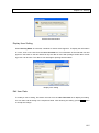
Run Project
After the configuration and generation of a project, it is ready for execution.
Select Run
Project from Run menu will execute Lab-LINK runtime system and load the current Project
setting. A dialog will appear for you to select which workstation should be run.
Select a
workstation and press OK button to start the runtime system of the selected workstation.
2-15
Lab-LINK for Windows User Manual
Stop project
Stop the execution of a running project.
Tool
Tool menu provide the execution of Lab-LINK development Tools of PAM which includes:
Panel Editor ─ Start panel editor for user to edit a panel file.
TagView ─ Start TagView, the tool to help you test and debug a project.
Security Editor ─ Start Security Editor, the tool to manage users by setting their username,
password and privilege.
Report ─ Run Report and load report setting of current project.
SmartScript ─ Start SmartScript Editor, the tool to edit and debug script.
2-16
Chapter 2 PAM
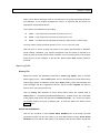
Help
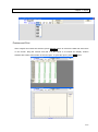
About PAM
Display version and license information of Lab-LINK.
License Version:Shows which license version of Lab-LINK is running. If a keypro is not
detected, it will show Evaluation.
Project Version: Project files version number of the opened project.
Program Version: Program file version number of PAM.
System Info: Information recorded in the Keypro including license version and I/O Tag capacity.
If no keypro is detected, Max. I/O Tags will be 0.
Version
Project Version
Program Version
System Info
2-17
Lab-LINK for Windows User Manual
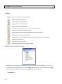
Toolbar
Toolbar contains the most often used menu items:
New ─Create a new project.
Open─Open an existed project.
Save─Save the opened project.
Close─Close the opened project.
TagAdmin─ Open Tag Administration Dialog for tag management.
Generate─Generate the opened project.
Run Project─Run the selected workstation of the opened project.
Stop Project─Stop the running project.
Report─Run the report setting of the selected workstation of the opened project.
TagView─Run TagView.
Security─Run Security Editor.
Help─Open Lab-LINK Help online document
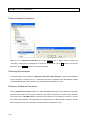
Module Page in Project Window
Module page of project window display module structure of each workstation in a tree view.
Workstations are top level node with Tag database and modules as their child node. Press
button before each node to expand it and press
Workstation
2-18
button will collapse it.
Chapter 2 PAM
Basic setting of the workstation includes Identification, Security and Execution. See
Workstation chapter for details.
TAG Database
Used for management of the Tag database. Tags can be created and their properties
including Init or retain value can be set. See Tag chapter for details.
Alarm
Used for Alarm basic setting and Alarm Tag settings.
Alarm is further divided into 8
categories:
Digital ─ Used for digital alarm. User can specify an alarm occur when an alarm Tag change
from 0 to 1 or 1 to 0.
High/Low Alarm ─ Used for analog alarm. A high limit and a low limit can be set. If the alarm
Tag value is greater than the high limit, a high alarm occurs. If the alarm Tag value is smaller
than the low limit and the low alarm occurs.
HH/H/L/LL Alarm ─ Used for analog Alarm. Similar to High/Low alarm but provide a second
set of high-high and low-low limit setting. A high-high alarm occurs when the alarm tag value
is greater than the high-high limit while a low-low alarm occurs if the value is smaller than the
low-low limit.
Rate of Change Alarm ─ Used for analog alarms. If the rate of change of the alarm tag is
greater than a set limit, an alarm occurs.
Deviation Alarm ─ Used for analog alarm.
A base value and a deviation are set. If the
alarm tag value is greater or smaller than the base by the value of the deviation then the
alarm occurs.
Timeout ─ Used for digital alarm. When the state of a digital alarm tag changed, it is
compared to the value of a referenced Tag. If the alarm Tag does not change as the
referenced Tag within a preset time limit, an alarm occurs.
Trip ─ Used for digital alarm. When the state of a digital alarm tag changed, it is compared to
the value of a referenced Tag. If the referenced Tag does not change in the preset manner, an
2-19
Lab-LINK for Windows User Manual
alarm occurs.
Event ─ used for digital Tags. Any change on the state of the Tag is recorded as an event.
Please see Alarm chapter for alarm details.
Data
This module is used to define how Tag data are stored. It can store Tag data into files with
specified time interval. Two data file formats are supported by this module:
Lab-LINK Data files (XDF): This is a Lab-LINK proprietary binary format used by
SmartPanel object and Lab-LINK Report. Select this file type if data will be presented by
Lab-LINK.
Text files (TXT): Data will be stored as text files. Select this file type if data will be used by
other application such as spreadsheet or database.
Please see Data chapter for details.
Report
Report module use data files stored by Data module to create reports. Lab-LINK reports
provide three time span:
Daily Report
Monthly Report
Yearly Report
There are also two different report format:
Text Report
Trend Report
Please see Report chapter for details.
DDE Connection
DDE Connection can be used to share data with other applications. Please see DDE
Connection chapter for details.
2-20
Chapter 2 PAM
Network Connection
Network Connection is used to share Tag data among Lab-LINK workstations. Please see
Network chapter for details.
IO Driver
I/O Drivers are used to connect PLC, controller or any other I/O devices supported by
Lab-LIMK. Define communication parameters IO and I/O address mapping between Tags
and I/O points and the I/O Driver will communicate with the devices to access real ti me data
at runtime. Please see I/O Driver chapter for details.
OPC Connection
OPC Connection is used to integrate OPC Server provided by hardware venders or third
party with Lab-LINK. Through OPC connection, Lab-LINK will be able to communication with
the I/O devices it doesn’t support. Please see OPC Connection chapter for details.
Script
SmartScript is the built-in script language of Lab-LINK. Script can be run with Lab-LINK
project to provide user specific functions such as control logic or complex mathe matic
calculation.
Please read Script chapter and “SmartScript Reference Manual” for details.
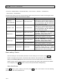
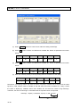
Project Files and Folders
A folder named “Project” is created under Lab-LINK folder after installation. The path should be
“C:\LabLINK\Project\” in a typical installation. Every time you create a project in PAM, a project
folder with the same name will be created under this system project folder. For example, a
project named “Proj1” should create a project folder with path “C:\LabLINK\Project\Proj1”.
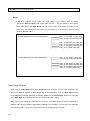
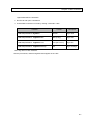
Files and folders will also be created for a project. For a project named “Proj1” with one
workstation named “Wks1”, the project files and folders under its project folders include:
Folder/File
Description
Referenc
e Path
2-21
Lab-LINK for Windows User Manual
Runtime configuration files of workstation
Wks1. These files are created when the
project is generated by PAM.
Panel files.
~1
BMP files used by panel objects.
~2
WMF files used by panel objects.
~3
Wav files used by panel objects.
~4
Text files used by panel objects.
~5
Default Data files storage
~6
SmartScript files
Project basic information
Backup of Lab-LINK.pjt
modified by PAM.
before
it
is
Workstation configuration of Wks1.
Backup of Wks1.pam before it is modified
by PAM.
Runtime shortcut for workstation Wks1.
註:Reference Path is the shorthand notation for the frequently used path in Lab-LINK project. It is
strongly recommended that they are used whenever it’s possible during panel object
configuration. Please read Appendix for Reference Path details.
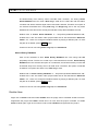
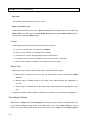
File Page in Project Window
Click on File tab in Project Window to show this page. A tree view shows the sub folders and
files under the project folder. Project subfolders discussed in previous section are represented as
nodes in the tree view.
2-22
Click on
to expand a node and click on
to collapse it.
Chapter 2 PAM
File Operation
Add
Right click on a subfolder node to show its popup menu. Select “Add … File” to add a
new file of that type. A dialog will appear to request for a file name.
Enter file name and
press OK button. The new file will be created and the associated application that can edit
that file will be run.
For example, right click on Pnl Panel File node, select Add Panel
File and enter a panel file name will run Panel Editor to edit the newly created file.
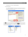
Import
Right click on a subfolder node to show its popup menu. Select “Import … File” to copy
an existing file to the folder in current project. A dialog will appear to let you select an
existing file. Press Import button after a file is selected. The file will be copy to the
project.
2-23
Lab-LINK for Windows User Manual
Delete
Right click on a file name to show its popup menu and select “Delete” to delete the file. A
confirm message box will appear. Press OK button to confirm the deletion or press
Cancel button to cancel the operation.
Content
Right click on a file name to show its popup menu and select “Content” to open the file.
The application associated with that type of file will be run and the file selected will be
loaded for editing or display. Double click on a file name has the same effect.
2-24
Chapter 2 PAM
Management of Other Files
Management of other types of files is very similar to the operation of panel files. The files
include BMP graphic files, WMF graphics files, WAV sound files, TXT text files, DAT data
files, CSL script files. File page of Project windows provide Add, Import, Delete and
Content operation for these files. Please follow the instructions discussed above for
panel file to handle these files. When Content is selected for a certain file, the application
associated with that type of file will be run to open the file for viewing or editing.
Lab-LINK provide sample library for BMP graphic files, WMF graphic files and WVA
sound files. User can import these file from the resource folder of Lab-LINK into their
project. Location of the resource folder is at “C:\lablink\resource” for a typical installation.
Three folders, BMP, WMF and WAV, store the three types of sample files. BMP and WMF
folders contain subfolders for several categories of graphic files.
Script File
Please note that adding a Script File in File page is not the same as adding a Script
module in Module Page.
project is run.
The file added in File page won’t run automatically when the
Only a Script File referenced by a Script module in Module page will be
loaded when the project is run. Please read Script chapter for details. Please refer to
Script chapter for details.
2-25
Chapter 3
Workstation
In a Lab-LINK project, the tasks of a computer running Lab-LINK are defined in a workstation.
This chapter will discuss the basic setting of a workstation. Detail description of the setting of each
module in a workstation will be discussed in the chapters follows.
Workstation
Workstation contains all the setting used by a computer running Lab-LINK. Complete workstation
setting may include the followings:
•
Workstation Basic Setting
•
Tag Database
•
Alarm
•
Data
•
Report
•
I/O Driver
•
DDEConenction
•
OPC Connection
•
Network Connection
•
Script
Number of workstations needed for a project depends on the tasks performed by each computer.
In general, single machine project that involves only one computer needs one workstation only,
and a network project involving multiple computers may need to setup several workstation.
However, because only one workstation is needed for several computers performing exactly the
same tasks, the number of workstations needed may be less than the computers involved,
3-1
Lab-LINK for Windows User Manual
Settings of different workstation’s module are independent except the Tags defined in Network
Connections whose real time data will be shared among Server and Client workstations.
Files in
a project can be used by all workstations and are store in the corresponding subfolder under the
project folder.
Basic Setting of Workstation
Basic Setting includes some basic information related to a workstation: its network identification,
security file location and project start settings.
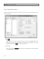
Right click on a workstation to show its popup menu and select Basic Setting, a dialog appears.
There are three pages in the dialog:
Identification
Click on ID Tab to show Identification page. This page defines the computer name, IP
address and an optional remark field of the workstation. This information will be used in
Network Connection configuration. You can ignore this setting for a single machine
project.
Either a computer name or a fixed IP address is mandated when a workstation is defined
as a Network Server. Up to 4 IP addresses which may be used by different Network
Clients can be set for a workstation. Please read Network chapter for Network
Connection details.
3-2
Chapter 3 Workstation
Security
Click on Security page to define the location of Security Setting file.
Security Setting
file contains Lab-LINK user database which define the user name, password and privilege.
The information is used for authentication when users are operating Lab-LINK runtime
system.
Default Security Setting path is at Lab-LINK system folder (C:\LabLINK\System4 for a
typical installation) and its file name is “ScrMan.xdb”. By selecting User Defined Path
and enter a different path in this dialog, Lab-LINK runtime system fill try to find the
Security Setting file in the user specified location at runtime. Lab-LINK project
maintenance staff is responsible of placing the Security File at the specified location to
guarantee. Please refer to Security chapter for security details.
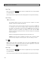
Execution
Click on Execution tag to select Execution page. This page defined the Root Panel and
the applications that need to start with the project.
A Root Panel is the first panel file loaded by Lab-LINK runtime system when it starts a
project. Default Root Panel has the same file name as the workstation. Enter a different
panel file name in the Root Panel File field to replace the default setting.
It is also possible to specify some applications to be run as the Lab-LINK runtime starts.
3-3
Lab-LINK for Windows User Manual
This is most often used to start add-on module of Lab-LINK. By entering the command to
execute the add-on module or any other application program you wish to run, they will be
run when the Lab-LINK runtime project is executed. Please remember to include all
necessary parameters in the command line.
Advanced
Click on Advanced to show the advanced setting page. Clcik on Enable check box and
enter a number in the Idle Time field to set the auto logout function.
During run time,
this setting will automatically log out users after the specified time expires without any
keyboard or mouse operation on the system.
This setting I s to prevent unauthorized operation when a user leave the site but forget to
logout from the system.
3-4
Chapter 3 Workstation
Add Workstation
Right click on a workstation and select Add Workstation from the popup menu, a dialog appear
to request for a new workstation name. Enter a name and press OK button, a new workstation is
created and appear as new node in the project tree.
3-5
Lab-LINK for Windows User Manual
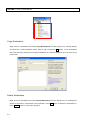
Copy Workstation
Right click on a workstation and select Copy Workstation from the popup menu, a dialog appear
to request for a new workstation name. Enter a name and press OK button, a new workstation
with exact the same setting as the original workstation is created and appear as a new node in the
project tree.
Delete Workstation
Right click on a workstation and select Delete Workstation from the popup menu, a message box
appear to request for confirmation of this operation. Press OK button to delete the workstation or
press Cancel button to cancel the operation.
3-6
Chapter 3 Workstation
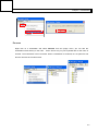
Rename
Right click on a workstation and select Rename from the popup menu, you can edit the
workstation name directly on the node.
Press <Enter> key on your keyboard after a new name is
entered. The workstation is then renamed. When a workstation is renamed, its root panel file will
also be renamed to the same name.
3-7
Chapter 4
Tag
Tag
Tag is the “carrier” of real time data in Lab-LINK. It is transfer among Lab-LINK modules and
Lab-LINK runtime kernel will guarantee the consistent and update of Tag data. For example, a
temperature reading is assigned to a Tag named TEMP001 by a PLC Driver. If the Tag is also
referenced by a DigiMeter object in SmartPanel, whenever a new temperature reading is scanned
by the PLC Driver, the number display by the DigiMeter object will be updated.
Tag Manager
Tag Manager plays the key role in Lab-LINK runtime system kernel. It is responsible for the
transferring of real time Tag data among modules. Its major task includes:
Maintain the consistency of Tag data among modules.
Control the Tag data flow among modules such that only the modules use that Tag receive
its update to achieve high efficiency.
Lab-LINK Tag can be divided into two categories: System Tag and User Tag. System Tags are
created by Lab-LINK runtime system to store key system information and their names always
start with “$”. User Tag is defined by users for their specific purpose and their names are given by
user.
Tag Naming Rule
Lab-LINK has these naming rules for Tag:
All alphanumeric character and some symbol characters such as “-“ and “_” can
be used. Chinese characters can also be used.
4-1
Lab-LINK for Windows User Manual
Some symbol characters are not allowed in Tag name: ! . [ ] ` / \ : * ? “ < > | # $ % & ‘( ) + , ;
=@^{}~
Tag name cannot start with a numeric character, but they are allowed in other place. Ex.
1Tag cannot be used but Tag1 is allowed.
The limit on the number of characters in a Tag name is 8. A Chinese character will be
counted as two characters.
Tag name is case sensitive. Ex. Tag1 and TAG1 are two different Tags.
Tag Data Structure
There is no need to declare data type for Tag. However, every Tag contains these data field:
Name – Name of the Tag
State – State of the Tag. Possible states include:
Unknown: The initial state of a Tag when Lab-LINK is started
Uncertain: Reserved.
Online: For an I/O Tag means the corresponding data on the I/O device can be normally
accessed. For a non-I/O Tag, it is online when any of the Lab-LINK module accesses
it.
Offline: The corresponding data on the I/O device can not be normally accessed.
Output Fault: The last output attempt to write to the corresponding data on the I/O device
failed.
Date – The date when last value or message change is detected on the Tag. The date
format is Year/Month/Date.
Time –The time when last value or message change is detected on the Tag. Time format is
Hour:Minute:Second.
Value – The newest value of the Tag. It is stored as a floating number with precision of about
15 or 16 digits.
Its range is – Negative:-1.797693134862316 E+308~-4.94065E-324;
Positive: 4.94065E-324~1.797693134862316E+308.
Message – The newest text message store in the Tag. It is stored as standard text string and
its length limit is 80 characters. (A Chinese character is counted as two characters.)
4-2
Chapter 4 Tag
Tag Manager Dialog
Usually, the first step to configure a workstation is to define its Tag database.
Double click on the
Tag node of the workstation will open the Tag Manger dialog. Tags can be added, edited,
renamed and deleted using this dialog.
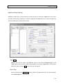
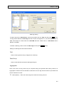
Tag Manager
Left side of the dialog is the Tags list showing the names, init value, retain setting and remark of
all user defined Tag. Select a Tag by left click on its name and its detailed setting is shown on the
right.
Init Value – Select this item to set the initial value and/or message of the Tag when
Lab-LINK runtime is started.
Value: The assigned to the Tag when Lab-LINK runtime system starts.
Message: The text message assigned to the Tag when Lab-LINK runtime system starts.
If no Init Value is set for the tag, its value will be 0 and its message will be blank when
runtime system starts.
Retain Value – Selecting this item means Tag value should be retained. When Lab-LINK
runtime system ends, value of the Tag will be saved. Next time Lab-LINK is started, the
saved value will be assigned to the Tag as its initial value.
Remark – A short text string can be entered into this field and used as the description of
the Tag.
4-3
Lab-LINK for Windows User Manual
Note:Init Value and Retain Value cannot be selected at the same time.
System Tag
Besides user Tags, there are some Tags created automatically by the system. These Tags are
called System Tag. All System Tag names start with “$”. Name and application of the System Tags
are described as follows:
$DISK: Its value shows the remaining space in the hard disk in M Bytes。
$EXIT: When its value is set to “1”, Lab-LINK runtime system will end. It is usually
assigned to a Button object in SmartPanel and used to end the runtime system when a
user presses the button.
$TIME: Its value increase by “1” every second.
$USER: Its value is the privilege of current logged-in user, and its message is his or her
user name.
$ALARM*: Its value is the number of active alarms and its message is the latest alarm
message.
$ALM_PRI*: Its value is the highest Priority value of unacknowledged active alarms.
$NEW_ALM*: Whenever a new alarm occurs, its value is set to “1”.
$LOGOUT: When its value is set to “1”, current user will be logged out.
$RUN: During the execution of Lab-LINK runtime, its value will be set to “1”. Its value will
be set to “0” when the Lab-LINK runtime system ends.
*These System Tags are related to Alarm module.
Add Tag
4-4
Chapter 4 Tag
Add Tag dialog
Press Add button in the Tag Manager dialog to add a new Tag. A small dialog will appear to
request for a new Tag name. Enter a name following Tag naming rule and press OK button. A new
Tag is created for the workstation. You can then set continue to do the further setting on the Tag.
Delete Tag
Select a Tag from the Tags list and press Delete button. If the Tag is already used by other
modules, a message box showing which modules are using it appears to request for confirmation
on the deletion. Press OK button to delete the Tag and settings related to the Tag in all the
modules will also be deleted. Otherwise, press Cancel button to cancel the operation. If the Tag is
not used by any module, it will be deleted immediately without the confirmation.
4-5
Lab-LINK for Windows User Manual
Delete Tag
Note: When a Tag is deleted, only the setting related to the Tag in currently editing workstation will
be deleted. If other workstation also uses this Tag, you may need to do the deletion in that
workstation separately. Tag settings in panel file are also not affected by the deletion mode
here. If needed, you should modify object setting in each panel file by yourself.
Rename Tag
Select a Tag from the Tags list and press Rename button to rename the Tag. If the Tag is already
used by other modules, a message box showing which modules are using it appears to request for
confirmation on the renaming. Press OK button to rename the Tag or press Cancel button to
cancel the operation. If OK is pressed, the message will disappear to allow you to edit the Tag
name directly on the Tags list. When you finish editing, pressed “Enter” key on your keyboard and
settings related to the Tag in all the modules will be modified to reflect the change. If the Tag is not
used by any module, it can be renamed without the confirmation.
4-6
Chapter 4 Tag
Note: When a Tag is renamed, only the setting related to the Tag in currently editing workstation
will be deleted. If other workstation also uses this Tag, you may need to do the renaming in
that workstation separately. Tag settings in panel file are also not affected by t he renaming
mode here. If needed, you should modify object setting in each panel file by yourself.
Tag Basic Setting
Right click on Tag node and select Basic from the popup menu, a dialog appears. You can define
where the retained Tag value is stored in the dialog.
Selecting Default Path indicates that you
want to use the system default location for the retained value file. If User Defined is selected, you
should enter a path in the field below which will be used to store the retained Tag value.
4-7
Lab-LINK for Windows User Manual
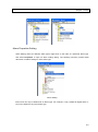
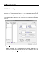
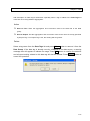
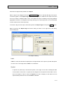
Tag Admin
Click on the Tag Admin button
on the toolbar, the Tag Administration window
will appear. This tool can be used to add, delete or rename tags for each workstation. It
can also be used to manage Panel Tags and copy tags among workstations.
Left half of the Tag Administration windows list all the workstations in the project. Click on
a workstation, its tags will be shown on the right half of the window. Click on the Panel Tag
node on top of the workstation list will show all panel tags in this project. The System tag
check box on the upper right corner of the windows can be is used to switching whether
the system tags of the selected workstation will be shown or not. To close the Tag
Administration windows, click on the X button on upper right corner of the window.
4-8
Chapter 4 Tag
Tag Administration windows provide the following tag operations:
New: After selecting a workstation, right click on the right half of the window and select
New from the popup menu, the New Tag dialog will appear.
Enter a new tag name and press OK. Tag content dialog appear to allow detail setting of
the new tag. Finish detail setting and press OK, the new tag will appear in the tag list of
the workstation.
Delete: Right click on a tag in the tag list and select Delete from the popup menu, a
message appears to request confirmation for deleting the selected tag. Press OK to
confirm and delete the tag, or press Cancel to cancel the operation.
If the tag to be deleted has been defined or referenced in any of the module of the
workstation, the delete operation will cause the Module List window to appear. The
windows will show which modules have used this tag and request the confirmation to
delete the tag.
4-9
Lab-LINK for Windows User Manual
If OK button is pressed, any setting related to the tag in each of the shown module s will all
be deleted. Please note that the removal of module definition of the deleted tag is
restricted to the selected workstation only. Any reference to this tag in other workstation
will not be affected by this operation.
Rename: Select the tag to be renamed from the tag list. Right click on it and select
Rename from the popup menu. The selected tag will be high lighted and an editing cursor
will appear on it to allow editing of its name using the keyboard. After a new name is
entered, press <Enter> key on the keyboard to complete the operation.
4-10
Chapter 4 Tag
Similar to the delete operation, if the renamed tag has be used in any of the module setting, a
Module List will appear to show which modules have used the tag request for confirmation. If the
operation is confirmed, all setting regarding the tag will be renamed as well. This operation is also
restricted to the workstation under modification only.
Open: By right clicking a tag in the tag list and selecting Open from the popup menu, its
Tag content dialog will be opened. After editing of its detail setting, press OK to complete
the editing, or press Cancel to discard the operation.
Double click on a tag can also open the Tag content dialog.
Copy: Select a tag from the tag list and drag it to another works tation in the workstation list
can copy the tag to the workstation.
4-11
Lab-LINK for Windows User Manual
If the copied tag is already defined in the target workstation, a Copy tag dialog will appear
to display the detail setting of the tags of the same name in both source and target
workstation. Press OK to confirm and overwrite the original tag in the target workstation,
or press Cancel to cancel the operation.
4-12
Chapter 4 Tag
Sort: To help user easily find a tag, users can click on column titles of the tag list to display
tags in ascending or descending order by the selected column.
Left click on Tag name column title to sort the tags by their name and a △ symbol appears
to indicate that the tags are listed in ascending order. Click on the column title again. A ▽
symbol is shown and the tags are sorted in descending order. Click on the title again and
the symbol disappears. The tags will be listed in unsorted order. Similar operation can be
performed on the Remark column to sort tags according to their remarks.
4-13
Chapter 5
Alarm
Introduction
Alarm module is used to provide alarming function in Lab-LINK. User can define alarm condition
and how the system should respond to the alarm.
There some special requirements if certain alarm features are used:
Sound card/interface and speaker are needed if sound or voice annunciation is expected
when alarms occur.
Dot matrix printers are recommended for alarm printing
Features
Alarm messages are user defined.
Both I/O Tags and non-I/O Tags can be defined as alarm Tags.
Alarm can be assigned Priority to determine which alarm should be processed first.
Alarm message can be printout immediately.
Eight types of alarm condition can be defined.
Operator can acknowledge alarms when they occur.
Alarm message and Reset message can be logged in a history file.
Active alarm and alarm history can be shown separately.
LogView alarm report program let user query of alarm records by time or categories and
print them as report.
Various actions can be taken when alarms occur.
5-1
Lab-LINK for Windows User Manual
Architecture
Same as other modules, Alarm module receive real time Tag data from Tag Manager and can
communicate with other modules through Tags. Alarm module can respond with the change of Tag
data to reflect its alarm status and send the status to other module if necessary.
Alarm can be divided to two parts:
Alarm Manager – It is responsible for detecting of any alarm condition and conduct actions
when alarms occur.
Log Manager – It is responsible for the logging of alarm history.
Alarm Processing
There are three stages from the occurrence till the clearing of an alarm:
Alarm: The state of an alarm Tag changes from normal to abnormal. Alarm action such as
printing and alarm output will be taken when an alarm occurs.
Acknowledge: Operator conduct an operation on Lab-LINK to indicate that it acknowledge
the alarm.
Reset: The state of an alarm Tag changes from abnormal back to normal.
Acknowledging may or may not be conducted during the alarm process. This may due to the
alarm reset before any operator has the opportunity to acknowledge it or acknowledgement is never
expected. Besides, it is also possible that an alarm is considered reset as soon as it is acknowledged.
In this case, it won’t have the reset stage.
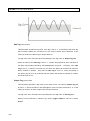
Alarm Logging
Alarm provide alarm message logging function to record alarm history. There are two alarm logging
system in Lab-LINK: Alarm Database and Alarm History File.
Alarm Database
Alarm Databases are real time databases storing alarm messages in system memory
5-2
Chapter 5 Alarm
during Lab-LINK runtime. The databases can be saved to files when Lab-LINK ends
and the files can be loaded back to memory when Lab-LINK starts.
You can choose to
store Active Alarm (alarms that are not reset) and Alarm History (records of past
alarms that are reset) in two separate databases (Dual Log) or in the same single
database (Single Log).
Due to the nature of memory storage, the number of alarm
records the databases can hold is limited in either case. A maximum of 1024 records
can be stored in either Active Alarm Database or Alarm History Database. Old reco rd
will be flushed out on a first in first out base. Records in both databases can be shown
using an Alarm Log object in SmartPanel.
Alarm History File
Alarm History File is a text file recording the alarm, acknowledge and reset messages
records by time. It can be viewed, queried and printed using the add-on module
LogView alarm report program.
Alarm Log Format
Messages are logged at each alarms stages, so there are three kinds of messages: alarm
message, acknowledge message and reset message
If Single Log is used, a complete reset message contains the following information:
Alarm DateTime AlarmName AlarmMessage, AckDateTime Acked by User
Reset DateTime AlarmName ResetMessage
Ex.
2005/01/02 10:20:05 Reactor Temperature too high, 2005/01/02 10:21:04 Acked by User A
2005/01/02 10:30:25 Reactor Temperature normal
If Dual Log is used, Active Alarm Database contains both alarm and acknowledge message with
format:
Alarm DateTime AlarmName AlarmMessage, AckDateTime Acked by User
When the alarm is reset, the record will be removed from Active Alarm Database, combined with
reset message and stored into Alarm History Database with the format:
Alarm DateTime AlarmName AlarmMessage, Reset DateTime ResetMessage,
5-3
Lab-LINK for Windows User Manual
AckDateTime Acked by User
Ex.
Reactor Temperature, 2005/01/02 10:20:05 too high, 2005/01/02 10:30:25 normal,
2005/01/02 10:21:04 Acked by User A
Note: mean the text behind should be part of the previous line
Alarm Types
There are eight different types of alarm conditions:
Digital Alarm: Suitable for digital Tags. Can be further divided to two sub types D1 and D0.
D1 alarm occurs when Tag value is “1” and D0 alarm occurs when Tag value is “0”.
High/Low Alarm: Suitable for analog Tags. A high limit and a low limit can be defined. When
Tag value is greater than or equal to the high limit, High alarm occurs. If Tag value is smaller
than or equal to the low limit, Low alarm occurs.
HH/H/L/LL Alarm: Suitable for analog Tags. Similar to High/Low alarm but with a second set
of limits. When Tag value is greater than the high-high limit, HH alarm occurs. If Tag value is
smaller than the low-low limit, LL alarm occurs.
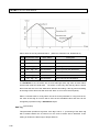
Rate of Change Alarm: Suitable for analog Tags. Alarm occurs when the speed of change
of alarm Tag value exceed a specified limit.
Deviation Alarm: Suitable for analog Tags. Based on a specified Base value, alarm occurs
when the different of the Base value and the alarm Tag value is greater than or equal to
the specified Deviation.
Timeout Alarm: Suitable for digital Tags. A Reference Tag is compared with the alarm Tag.
The alarm Tag value must change as the Reference Tag within a specified time limit.
Otherwise, alarm occurs. This type of alarm can be further divided into two subtypes: T0
and T1.
T0 alarm occurs if alarm Tag and the Reference Tag are at the same state after
the time limit. T1 alarm occurs if alarm Tag and the Reference Tag are at the opposite
state after the time limit. There is no automatic reset for Timeout alarm.
Trip Alarm: Suitable for digital Tags. A Reference Tag is compared with the alarm Tag. It is
further divided into three subtypes: X0, X1 and XC. X0 alarm occurs if the Reference Tag
is at the same state when the alarm Tag changes.
5-4
X0 alarm occurs if the Reference Tag
Chapter 5 Alarm
is at the same when the alarm Tag changes. X1 alarm occurs if the Reference Tag is at
the opposite state when the alarm Tag changes. XC alarm occurs if the alarm Tag change
but the Reference Tag doesn’t.
Event: Suitable for digital Tags. Any state change of the alarm Tag is recorded as an event.
There is no reset for an event.
Expand and Collapse of Alarm Node
In Project Window, click on
before the Alarm node to expand alarm module and show the
eight alarm types as nodes in the tree view. To collapse
GP-I the Alarm node, click on
node.
before the Alarm
B
Basic Setting
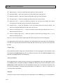
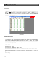
Right click on Alarm node and select Basic from the popup menu to open its Basic Setting dialog.
Select Basic Setting
The Dialog is used to set alarm logging and printing:
5-5
Lab-LINK for Windows User Manual
Basic Setting Dialog
Alarm Log Option
Single Log (Combine Active/History)
Combine active alarm messages and alarm history in the same database. Alarm,
acknowledge and reset messages are all recorded in this database in the sequence of
occurring time.
Dual Log (Separate Active/History)
Active alarm and alarm history are store separately in two different databases. Alarm
and acknowledge message of any active alarm is kept in the Active Alarm Database.
When an alarm reset, its alarm and acknowledge messages are removed from the
Active Alarm Database, combined with the reset message, and stored in the Alarm
History Database as a history record.
Alarm Printer
Alarm messages can be printed immediately by setting Print Message in alarm action
setting. The setting is used to specify which printer will be used for alarm message
printing. A dot matrix printer is recommended for this application due to its line printing
5-6
Chapter 5 Alarm
nature. Since alarm messages code is sent directly to the printer bypassing Windows ’
Print Manager, if non English messages are used, it is expected that the printer has
appropriate code and fonts built in.
Three options are available for this setting:
LPT1 — Use the printer connected to printer port LPT1.
LPT2 — Use the printer connected to printer port LPT2.
None — No alarm printing despite the setting in alarm action of alarm Tags.
You may need to remap a network printer to LPT1 or LPT 2 if one is used.
Note: Be sure to set up at least one printer for the printer port specified in Windows
Printer Setting. Otherwise, your system will appear hung and cease to respond for a
period as long as several minutes when an alarm occurs and the system try to locate a
printer to print out the message. To prevent this, please select None if alarm printing is
not used.
Alarm Log Path
History File
Besides the alarm log databases discussed in Alarm Log Option, there is another
alarm logging choice – alarm History File. This is a text file used to record alarm history.
If this logging option is selected in alarm Tags’ Action setting, alarm, acknowledge and
reset messages will all be logged into this file. Add-on module LogView can then be
used to view, query and print the log.
Click on History File checkbox to select storing alarm history file. Default Path of
History File is “..\Project\ProjectName\dat\Histort.log”, located at the “dat” sub folder
under project folder that is also denoted as Reference Folder “~6\”. Users can change
this default location by keying a different path. To reset the path to its default, press
Default button.
Active Alarm Database
Click on the checkbox to store Active Alarm Database into a file using Lab-LINK
proprietary format. The file can contain up to 1024 latest alarm records. Active Alarm
Database won’t be stored if this option is not selected, and all active alarm records will
5-7
Lab-LINK for Windows User Manual
be flushed away from memory when Lab-LINK ends. However, not storing Active
Alarm Database won’t an issue if Dual Log is used since it reflect the real time alarm
condition and will be detected again when Lab-LINK is started. Therefore, this option is
not selected as default when using Dual Log. For Single Log, this is the only alarm
database file used and should usually be selected to keep alarm database records.
Default Path of Active Alarm Database is “..\Project\ProjectName\dat\Alarm.xdb”,
located at the “dat” sub folder under project folder that is also denoted as Reference
Folder “~6\”. Users can change this default location by keying a different path. To reset
the path to its default, press Default button.
Content of can be view using Alarm Log object in SmartPanel.
Alarm History Database
Click on the checkbox to store Alarm History Database into a file using Lab-LINK
proprietary format. The file can contain up to 1024 latest alarm records. Alarm History
Database won’t be stored if this option is not selected, and all alarm history records will
be flushed away from memory when Lab-LINK ends. Therefore, this option is selected
as default. This option has effect only if Dual Log is used.
Default Path of Alarm History Database is “..\Project\ProjectName\dat\Resume.xdb”,
located at the “dat” sub folder under project folder that is also denoted as Reference
Folder “~6\”. Users can change this default location by keying a different path. To reset
the path to its default, press Default button.
Content of can be view using Alarm Log object in SmartPanel.
Disable Alarm
Right click on Alarm node and select Disable from the popup menu to disable all alarm function.
Regenerate the project and Alarm module won’t run next time the project is started. To enable
Alarm module again, right click on Alarm node to select Enable and regenerate the project.
5-8
Chapter 5 Alarm
Alarm Properties Setting
Alarm Setting varies for different alarm types. Right click on the node of a particular alarm type
and select Properties to open its alarm setting dialog. The following sections provide detail
discussion on alarm setting for each alarm type.
Alarm Setting
Note: Each can only be added into an alarm type. For example, it Tag 1 added to Digital Alarm, it
can not be added to any other alarm type.
5-9
Lab-LINK for Windows User Manual
Digital Alarm Setting
Suitable for digital Tags, this alarm type can be further divided into two sub types: D1and D0. D1
alarm occurs when Tag value is “1” and D0 alarm occurs when Tag value is “0”
Tags: Add
Tags list shows all the Tags in Tag database. Click on the check box System Tag to show
system Tags in the list if one of system Tags needs to be used as a digital alarm. You can also
add a new Tag by pressing Add button on top of the Tags list.
Alarm Tags
Select a Tag and press Add Alarm button to add it as a digital alarm Tag. The Tag will appear
in the Alarm Tags list.
Select a Tag in the Alarm Tags list and its alarm setting appears on the right half of the dialog.
5-10
Chapter 5 Alarm
Alarm Setting
Name (mandatory field)
This parameter defines the name of the alarm Tag when it appears in the a larm
message. The limit on the length is 80 characters.
A string enclosed in a pair of square brackets can appear in the beginning of Name and
a “|” character can be used in the category string to separate main category and
sub-category. The strings will be used by the add-on LogView alarm report module as
categories for queries. For example, the message for an alarm Tags with Name
“[Electrical System|Area A] Power panel VCB-1” and alarm message “Trip” may display
its alarm message as:
2006/01/01 12:00:00 [Electrical System|Area A] Power panel VCB-1 Trip
LogView will have two levels of categories for queries. User can search for alarm
records with major categories of “Electrical System” and minor category of “Area A”.
Type (mandatory field)
This parameter specifies sub type of digital alarm:
D1 — Alarm occurs when Tag value is “1”.
D0 — Alarm occurs when Tag value is “0”.
Priority (mandatory field)
When more than one alarm occurs at the same time, Priority is used to determine
which alarm will be handled first. Priority should be between 1~255 with the higher
value representing higher priority.
A system tag $ALM_PRI is used to show the highest Priority value in all active
unacknowledged alarms.
Halt Tag (optional field)
This parameter specifies a tag name. If the tag is set to “1”, processing of the alarm tag
will be halted. Neither the occurrence nor the reset of alarm will be detected. If this
5-11
Lab-LINK for Windows User Manual
setting is omitted, the alarm tag is always effective.
The tag name set in this field cannot be identical to the Tag name in Output Tag field.
When the value of the Halt Tag is set to “1”, system will suspend all alarm functions of
the alarm Tag including alarming, acknowledgement and reset.
Therefore, if the Halt
Tag is set to “1” after the occurrence of an alarm, the alarm will remain even when its
alarm condition is cleared.
Only after the Halt Tag is set to “0”, alarm processing of
this alarm tag can then be restored and the system will determine whether the alarm
should be reset or not.
Output Tag (optional field)
This parameter specifies a tag name. If the alarm occurs, the value of Output Tag will
be set to “1”. When the alarm is acknowledged or reset, its value will be set to “0”. If this
setting is omitted, no alarm output action will be performed.
The tag name set in this field cannot be identical to the Tag name in Halt Tag field.
Setting of this parameter is effective only when Trigger Output is also set in alarm
Action.
Alm Group (mandatory field)
This parameter specifies the Alarm Group the alarm tag belongs to. Alarm Group is a
number between 0~65535 and will be used by Alarm WAV Player object to determine
which wave file should be played. Please refer to SmartPanel Users’ Manual for detail
on the object.
Delay Time (optional field)
This parameter specify the time in seconds an alarm Tag reach its alarm condition
before the system recognize its alarm status and activate the subsequent alarm actions.
Delay Time is a number between 0~65535.
If Reset Delay option of the alarm tag is also checked, delay of the same time will also
be applied to alarm reset. When the alarm condition is cleared, the same amount of
time will also be waited before the system reset the alarm.
5-12
Chapter 5 Alarm
Reset Delay (optional field)
This parameter specifies whether the Delay Time setting will be applied to alarm reset.
If checked, alarm will not be reset until the specified delay time elapsed after alarm
condition is cleared. If this option is not checked, an alarm will be reset as soon as its
alarm condition is cleared.
Reset Msg (mandatory field)
This parameter specifies the content of the reset message. It is a string with length limit
of 80 characters.
Alarm Msg (mandatory field)
This parameter specifies the message content of the alarm message. It is a string with
length limit of 80 characters.
Remark (optional field)
A short description of the alarm tag. It’s a string used for descriptive purpose only.
Action (optional field)
These are options specifying what actions will be taken when the alarm occurs. Some
Actions may need the accompany setting of other fields.
Log to Database: Messages of the alarm will be logged to Active Alarm
Database and Alarm History Database. If this Action is not selected, message
of this alarm won’t be shown in Alarm Bar and Alarm Log objects in
SmartPanel. However Annunciator and Group Annunciator objects will still
reflect the alarm status of this alarm.
Reset When Acked: Acknowledging this alarm will also reset it.
Set $NEW_ALM: Set the value of system tag $NEW_ALM to “1” if this alarm
occurs.
Print Message: Print messages (including alarm, acknowledge and reset
messages) immediately when alarm condition of this alarm changed. A valid
printer port must be selected in Alarm Basic Setting for the option to be
5-13
Lab-LINK for Windows User Manual
effective. Be sure to install appropriate printer driver also.
Log to History: Log messages (including alarm, acknowledge and reset
messages) of this alarm to the Alarm History File. If this option is not selected,
messages of this alarm won’t be recorded in the history file. History File
checkbox must be selected in Alarm Basic Setting for this parameter to have
effect.
Trigger Output: Set the value of Output Tag to “1” when the alarm occurs.
This setting is effective only when an Output Tag name is also specified.
Play TTS Voice: When the alarm occurs, read the alarm message using TTS
(Text to Speech). Operating system must support TTS of the language used in
alarm messages for this setting to be effective.
Note: TTS needs the support of Windows Speech API (SAPI). Windows XP support
SAPI but Windows 2000. Besides, Windows XP only support TTS in some
languages.
Delete(D)
Press Delete(D) button to delete an alarm tag from Alarm Tags list and remove its alarm
settings.
□
Disable
If the checkbox is checked, the alarm setting of this alarm tag is disabled and no alarm
processing is performed on the tag at runtime. The disabled alarm tag will also appear in gray
color in the Alarm Tags list.
Close
Press Close button to end alarm setting and close the dialog.
Help
Press Help button to open help document related to this topic.
5-14
Chapter 5 Alarm
High/Low Alarm Setting
Suitable for analog Tags. A high limit and a low limit can be set in this alarm. High alarm occurs when
the value of alarm tag is grater than or equal to high limit and Low alarm occurs when the alarm tag
value is smaller than or equal to the low limit.
Tags: Add
Tags list shows all the Tags in Tag database. Click on the check box System Tag to show
system Tags in the list if one of system Tags needs to be used as a digital alarm. You can also
add a new Tag by pressing Add button on top of the Tags list.
Alarm Tags
Select a Tag and press Add Alarm button to add it as a digital alarm Tag. The Tag will appear
in the Alarm Tags list.
5-15
Lab-LINK for Windows User Manual
Alarm Setting
Name (mandatory field)
This parameter defines the name of the alarm Tag when it appears in the alarm
message. The limit on the length is 80 characters.
A string enclosed in a pair of square brackets can appear in the beginning of Name and
a “|” character can be used in the category string to separate main category and
sub-category. The strings will be used by the add-on LogView alarm report module as
categories for queries. For example, the message for an alarm Tags with Name “[Area
A|Reactor] Temperature” and alarm message “too high” may display its alarm message
as:
2006/01/01 12:00:00 [Area A|Reactor] Temperature too high
LogView will have two levels of categories for queries. User can search for alarm
records with major categories of “Area A” and minor category of “Reactor”.
Priority (mandatory field)
When more than one alarm occurs at the same time, Priority is used to determine
which alarm will be handled first. Priority should be between 1~255 with the higher
value representing higher priority.
A system tag $ALM_PRI is used to show the highest Priority value in all active
unacknowledged alarms.
Deadband (optional field)
This parameter specifies a dead band range. Dead band is designed to avoid the
annoyance of frequent alarm and reset of an analog alarm whose value is close to the
alarm limit. As shown in the figure below, the shaded area within alarm limits are the
dead bands.
5-16
Chapter 5 Alarm
Temperature℃
High Limit80
70
Deadband=10
Tag value curve
30
Low Limit20
Deadband=10
1
2
3
4
5
6
7
Time
Alarm status of the Tag with dead band:
Stage Temperature Value
Alarm Status
Description
1
Tag <80
Normal
2
Tag≧80
High Alarm
Exceed high limit
3
80> Tag≧70
High Alarm
Below high limit but still within deadband
4
70> Tag > 20
Normal (Reset)
Below high limit and dead band
5
Tag≦20
Low Alarm
Below low limit
6
30> Tag≧20
Low Alarm
Above low limit but still within deadband
7
Tag≧30
Normal
Above low limit and dead band
If a Deadband is set, the alarm will not reset although alarm tag value is within alarm
limit but still inside the dead band.
The alarm is reset only after the tag value is within
alarm limit and also out of the dead band. Without this setting, if the tag value oscillating
at the edge of the alarm limit will cause the alarm to occur and reset frequently. Besides
a constant value, a Tag name can also be set in this parameter.
Either a constant value or a Tag name can be set to this parameter. If a tag name is set,
the value of that tag at run time will be used as the deadband value and thus can be
changed by operators using a SmartPanel object.
Halt Tag (optional field)
This parameter specifies a tag name. If the tag is set to “1”, processing of the alarm tag
will be halted. Neither the occurrence nor the reset of alarm will be detected. If this
5-17
Lab-LINK for Windows User Manual
setting is omitted, the alarm tag is always effective.
The tag name set in this field cannot be identical to the Tag name in Output Tag field.
When the value of the Halt Tag is set to “1”, system will suspend all alarm functions of
the alarm Tag including alarming, acknowledgement and reset.
Therefore, if t he Halt
Tag is set to “1” after the occurrence of an alarm, the alarm will remain even when its
alarm condition is cleared.
Only after the Halt Tag is set to “0”, alarm processing of
this alarm tag can then be restored and the system will determine whether the alarm
should be reset or not.
Output Tag (optional field)
This parameter specifies a tag name. If the alarm occurs, the value of Output Tag will
be set to “1”. When the alarm is acknowledged or reset, its value will be set to “0”. If this
setting is omitted, no alarm output action will be performed.
The tag name set in this field cannot be identical to the Tag name in Halt Tag field.
Setting of this parameter is effective only when Trigger Output is also set in alarm
Action.
Alm Group (mandatory field)
This parameter specifies the Alarm Group the alarm tag belongs to. Alarm Group is a
number between 0~65535 and will be used by Alarm WAV Player object to determine
which wave file should be played. Please refer to SmartPanel Users’ Manual for detail
on the object.
Delay Time (optional field)
This parameter specify the time in seconds an alarm Tag reach its alarm condition
before the system recognize its alarm status and activate the subsequent alarm actions.
Delay Time is a number between 0~65535.
If Reset Delay option of the alarm tag is also checked, delay of the same time will also
be applied to alarm reset. When the alarm condition is cleared, the same amount of
time will also be waited before the system reset the alarm.
5-18
Chapter 5 Alarm
Reset Delay (optional field)
This parameter specifies whether the Delay Time setting will be applied to alarm reset.
If checked, alarm will not be reset until the specified delay time elapsed after alarm
condition is cleared. If this option is not checked, an alarm will be reset as so on as its
alarm condition is cleared.
Reset Msg (mandatory field)
This parameter specifies the content of the reset message. It is a string with length limit
of 80 characters.
High/Low Limit
High (mandatory field)
High limit of the alarm tag. If the value of the alarm tag is greater than or equal to
the limit, High Alarm occurs. This parameter can either be a constant value or a
tag name. If a tag name is set, the value of that tag at run time is used as high limit.
Alarm Msg
This parameter specifies the message content of the high alarm message. It is a
string with length limit of 80 characters. If no message is defined (the field is left
blank), High Alarm is disabled.
Low (mandatory field)
Low limit of the alarm tag. If the value of the alarm tag is smaller than or equal to
the limit, Low Alarm occurs. This parameter can either be a constant value or a tag
name. If a tag name is set, the value of that tag at run time is used as low limit.
Alarm Msg
This parameter specifies the message content of the low alarm message. It is a
string with length limit of 80 characters. If no message is defined (the field is left
blank), Low Alarm is disabled.
5-19
Lab-LINK for Windows User Manual
Remark (optional field)
A short description of the alarm tag. It’s a string used for descriptive purpose only.
Action (optional field)
These are options specifying what actions will be taken when the alarm occurs. Some
Actions may need the accompany setting of other fields.
Log to Database: Messages of the alarm will be logged to Active Alarm
Database and Alarm History Database. If this Action is not selected, message
of this alarm won’t be shown in Alarm Bar and Alarm Log objects in
SmartPanel. However Annunciator and Group Annunciator objects will still
reflect the alarm status of this alarm.
Reset When Acked: Acknowledging this alarm will also reset it.
Set $NEW_ALM: Set the value of system tag $NEW_ALM to “1” if this alarm
occurs.
Print Message: Print messages (including alarm, acknowledge and reset
messages) immediately when alarm condition of this alarm changed. A valid
printer port must be selected in Alarm Basic Setting for the option to be
effective. Be sure to install appropriate printer driver also.
Log to History: Log messages (including alarm, acknowledge and reset
messages) of this alarm to the Alarm History File. If this option is not selected,
messages of this alarm won’t be recorded in the history file. History File
checkbox must be selected in Alarm Basic Setting for this parameter to have
effect.
Trigger Output: Set the value of Output Tag to “1” when the alarm occurs.
This setting is effective only when an Output Tag name is also specified.
Play TTS Voice: When the alarm occurs, read the alarm message using TTS
(Text to Speech). Operating system must support TTS of the language used in
alarm messages for this setting to be effective.
Note: TTS needs the support of Windows Speech API (SAPI). Windows XP support
SAPI but Windows 2000. Besides, Windows XP only support TTS in some
5-20
Chapter 5 Alarm
languages.
Delete(D)
Press Delete(D) button to delete an alarm tag from Alarm Tags list and remove its alarm
settings.
□
Disable
If the checkbox is checked, the alarm setting of this alarm tag is disabled and no alarm
processing is performed on the tag at runtime. The disabled alarm tag will also appear in gray
color in the Alarm Tags list.
Close
Press Close button to end alarm setting and close the dialog.
Help
Press Help button to open help document related to this topic.
5-21
Lab-LINK for Windows User Manual
HH/H/L/LL Alarm Setting
Suitable for analog Tags. Two sets of high limits and low limits can be set in this alarm. High-High
alarm occurs when the value of alarm tag is grater than or equal to high-high limit; High alarm occurs
when the value of alarm tag is grater than or equal to high limit but smaller than the high -high limit;
Low alarm occurs when the alarm tag value is smaller than or equal to the low limit but greater than
the low-low limit; Low-Low alarm occurs when the alarm tag value is smaller than or equal to the
low-low limit.
Tags: Add
Tags list shows all the Tags in Tag database. Click on the check box System Tag to show
system Tags in the list if one of system Tags needs to be used as a digital alarm. You can also
add a new Tag by pressing Add button on top of the Tags list.
5-22
Chapter 5 Alarm
Alarm Tags
Select a Tag and press Add Alarm button to add it as a digital alarm Tag. The Tag will appear
in the Alarm Tags list.
Alarm Setting
Name (mandatory field)
This parameter defines the name of the alarm Tag when it appears in the alarm
message. The limit on the length is 80 characters.
A string enclosed in a pair of square brackets can appear in the beginning of Name and
a “|” character can be used in the category string to separate main category and
sub-category. The strings will be used by the add-on LogView alarm report module as
categories for queries. For example, the message for an alarm Tags with Name “[Area
A|Reactor] Temperature” and alarm message “too high” may display its alarm message
as:
2006/01/01 12:00:00 [Area A|Reactor] Temperature too high
LogView will have two levels of categories for queries. User can search for alarm
records with major categories of “Area A” and minor category of “Reactor”.
Priority (mandatory field)
When more than one alarm occurs at the same time, Priority is used to determine
which alarm will be handled first. Priority should be between 1~255 with the higher
value representing higher priority.
A system tag $ALM_PRI is used to show the highest Priority value in all active
unacknowledged alarms.
Deadband (optional field)
This parameter specifies a dead band range. Dead band is designed to avoid the
annoyance of frequent alarm and reset of an analog alarm whose value is close to the
alarm limit. As shown in the figure below, the shaded area within alarm limits are the
dead bands.
5-23
Lab-LINK for Windows User Manual
Alarm status of the Tag with dead band:
Stag
e
Temperature
Value
1
Tag <80
Normal
2
Tag≧80
High Alarm
Exceed high
high-high limit
3
Tag≧ 100
High-High Alarm
Exceed high-high limit
Alarm Status
Description
limit
but
below
4
90 > Tag≧ 100 High-High Alarm
Below high-high limit but still
within deadband
5
90 > Tag≧ 80 High Alarm
Below
high-high
limit
and
deadband but still above high limit
6
80 > Tag≧ 70 High Alarm
Below high limit but still within
deadband
7
70 > Tag≧ 20 Normal (Reset)
Below high limit and dead band
8
20 > Tag≧ 0
Low Alarm
Below low limit but above low-low
limit
Low –Low Alarm
Below low-low limit
Low –Low Alarm
Above low-low limit but still within
deadband
9
Tag <
0
10
10 > Tag≧ 0
11
20 > Tag≧ 10 Low Alarm
Above low-low limit and deadband
but still below low limit
12
30≧ Tag > 20 Low Alarm
Above low limit but still within
deadband
13
70 > Tag > 30 Normal (Reset)
Above low limit and deadband
If a Deadband is set, the alarm will not reset although alarm tag value is within alarm
limit but still inside the dead band.
5-24
The alarm is reset only after the tag value is w ithin
Chapter 5 Alarm
alarm limit and also out of the dead band. Without this setting, if the tag value oscillating
at the edge of the alarm limit will cause the alarm to occur and reset frequently. Besides
a constant value, a Tag name can also be set in this parameter.
Either a constant value or a Tag name can be set to this parameter. If a tag name is set,
the value of that tag at run time will be used as the deadband value and thus can be
changed by operators using a SmartPanel object.
Halt Tag (optional field)
This parameter specifies a tag name. If the tag is set to “1”, processing of the alarm tag
will be halted. Neither the occurrence nor the reset of alarm will be detected. If this
setting is omitted, the alarm tag is always effective.
The tag name set in this field cannot be identical to the Tag name in Output Tag field.
When the value of the Halt Tag is set to “1”, system will suspend all alarm functions of
the alarm Tag including alarming, acknowledgement and reset.
Therefore, if the Halt
Tag is set to “1” after the occurrence of an alarm, the alarm will remain even when its
alarm condition is cleared.
Only after the Halt Tag is set to “0”, alarm processing of
this alarm tag can then be restored and the system will determine whether the alarm
should be reset or not.
Output Tag (optional field)
This parameter specifies a tag name. If the alarm occurs, the value of Output Tag will
be set to “1”. When the alarm is acknowledged or reset, its value will be set to “0”. If this
setting is omitted, no alarm output action will be performed.
The tag name set in this field cannot be identical to the Tag name in Halt Tag field.
Setting of this parameter is effective only when Trigger Output is also set in alarm
Action.
Alm Group (mandatory field)
This parameter specifies the Alarm Group the alarm tag belongs to. Alarm Group is a
number between 0~65535 and will be used by Alarm WAV Player object to determine
which wave file should be played. Please refer to SmartPanel Users’ Manual for detail
5-25
Lab-LINK for Windows User Manual
on the object.
Delay Time (optional field)
This parameter specify the time in seconds an alarm Tag reach its alarm condition
before the system recognize its alarm status and activate the subsequent alarm actions.
Delay Time is a number between 0~65535.
If Reset Delay option of the alarm tag is also checked, delay of the same time will also
be applied to alarm reset. When the alarm condition is cleared, the same amount of
time will also be waited before the system reset the alarm.
Reset Delay (optional field)
This parameter specifies whether the Delay Time setting will be applied to alarm reset.
If checked, alarm will not be reset until the specified delay time elapsed after alarm
condition is cleared. If this option is not checked, an alarm will be reset as soon as its
alarm condition is cleared.
Reset Msg (mandatory field)
This parameter specifies the content of the reset message. It is a string with length limit
of 80 characters.
H/L Limit
H (mandatory field)
High limit of the alarm tag. If the value of the alarm tag is greater than or e qual to
the limit, High Alarm occurs. This parameter can either be a constant value or a
tag name. If a tag name is set, the value of that tag at run time is used as high limit.
Alarm Msg
This parameter specifies the message content of the high alarm message. It is a
string with length limit of 80 characters. If no message is defined (the field is left
blank), High Alarm is disabled.
L (mandatory field)
5-26
Chapter 5 Alarm
Low limit of the alarm tag. If the value of the alarm tag is smaller than or equal to
the limit, Low Alarm occurs. This parameter can either be a constant value or a tag
name. If a tag name is set, the value of that tag at run time is used as low limit.
Alarm Msg
This parameter specifies the message content of the low alarm message. It is a
string with length limit of 80 characters. If no message is defined (the field is left
blank), Low Alarm is disabled.
HH/LL Limit
HH (mandatory field)
High-High limit of the alarm tag. If the value of the alarm tag is greater than or
equal to the limit, High-High Alarm occurs. This parameter can either be a
constant value or a tag name. If a tag name is set, the value of that tag at run time
is used as high-high limit.
Alarm Msg
This parameter specifies the message content of the high-high alarm message. It is
a string with length limit of 80 characters. If no message is defined (the field is left
blank), High-High Alarm is disabled.
LL (mandatory field)
Low-Low limit of the alarm tag. If the value of the alarm tag is smaller than or equal
to the limit, Low-Low Alarm occurs. This parameter can either be a constant value
or a tag name. If a tag name is set, the value of that tag at run time is used as
low-low limit.
Alarm Msg
This parameter specifies the message content of the low-low alarm message. It is
a string with length limit of 80 characters. If no message is defined (the field is left
blank), Low-Low Alarm is disabled.
5-27
Lab-LINK for Windows User Manual
Remark (optional field)
A short description of the alarm tag. It’s a string used for descriptive purpose only.
Action (optional field)
These are options specifying what actions will be taken when the alarm occurs. Some
Actions may need the accompany setting of other fields.
Log to Database: Messages of the alarm will be logged to Active Alarm
Database and Alarm History Database. If this Action is not selected, message
of this alarm won’t be shown in Alarm Bar and Alarm Log objects in
SmartPanel. However Annunciator and Group Annunciator objects will still
reflect the alarm status of this alarm.
Reset When Acked: Acknowledging this alarm will also reset it.
Set $NEW_ALM: Set the value of system tag $NEW_ALM to “1” if this alarm
occurs.
Print Message: Print messages (including alarm, acknowledge and reset
messages) immediately when alarm condition of this alarm changed. A valid
printer port must be selected in Alarm Basic Setting for the option to be
effective. Be sure to install appropriate printer driver also.
Log to History: Log messages (including alarm, acknowledge and reset
messages) of this alarm to the Alarm History File. If this option is not selected,
messages of this alarm won’t be recorded in the history file. History File
checkbox must be selected in Alarm Basic Setting for this parameter to have
effect.
Trigger Output: Set the value of Output Tag to “1” when the alarm occurs.
This setting is effective only when an Output Tag name is also specified.
Play TTS Voice: When the alarm occurs, read the alarm message using TTS
(Text to Speech). Operating system must support TTS of the language used in
alarm messages for this setting to be effective.
Note: TTS needs the support of Windows Speech API (SAPI). Windows XP support
SAPI but Windows 2000. Besides, Windows XP only support TTS in some
5-28
Chapter 5 Alarm
languages.
Delete(D)
Press Delete(D) button to delete an alarm tag from Alarm Tags list and remove its alarm
settings.
□
Disable
If the checkbox is checked, the alarm setting of this alarm tag is disabled and no alarm
processing is performed on the tag at runtime. The disabled alarm tag will also appear in gray
color in the Alarm Tags list.
Close
Press Close button to end alarm setting and close the dialog.
Help
Press Help button to open help document related to this topic.
5-29
Lab-LINK for Windows User Manual
Rate of Change Alarm Setting
Suitable for analog Tags. The alarm occurs when the rate of change of the alarm tag value is greater
than a specified limit.
Tags: Add
Tags list shows all the Tags in Tag database. Click on the check box System Tag to show
system Tags in the list if one of system Tags needs to be used as a digital alarm. You can also
add a new Tag by pressing Add button on top of the Tags list.
Alarm Tags
Select a Tag and press Add Alarm button to add it as a digital alarm Tag. The Tag will appear
in the Alarm Tags list.
5-30
Chapter 5 Alarm
Alarm Setting
Name (mandatory field)
This parameter defines the name of the alarm Tag when it appears in the alarm
message. The limit on the length is 80 characters.
A string enclosed in a pair of square brackets can appear in the beginning of Name and
a “|” character can be used in the category string to separate main category and
sub-category. The strings will be used by the add-on LogView alarm report module as
categories for queries. For example, the message for an alarm Tags with Name “[Area
A|Reactor] Temperature” and alarm message “change too fast” may display its alarm
message as:
2006/01/01 12:00:00 [Area A|Reactor] Temperature change too fast
LogView will have two levels of categories for queries. User can search for alarm
records with major categories of “Area A” and minor category of “Reactor”.
Priority (mandatory field)
When more than one alarm occurs at the same time, Priority is used to determine
which alarm will be handled first. Priority should be between 1~255 with the higher
value representing higher priority.
A system tag $ALM_PRI is used to show the highest Priority value in all active
unacknowledged alarms.
Deadband (optional field)
This parameter specifies a dead band range. Dead band is designed to avoid the
annoyance of frequent alarm and reset of an analog alarm whose value change rate is
close to the alarm limit. As shown in the figure below, the shaded area within alarm
limits are the dead bands. Alarm resets only after its change rate is below the
deadband.
5-31
Lab-LINK for Windows User Manual
Halt Tag (optional field)
This parameter specifies a tag name. If the tag is set to “1”, processing of the alarm tag
will be halted. Neither the occurrence nor the reset of alarm will be detected. If this
setting is omitted, the alarm tag is always effective.
The tag name set in this field cannot be identical to the Tag name in Output Tag field.
When the value of the Halt Tag is set to “1”, system will suspend all alarm functions of
the alarm Tag including alarming, acknowledgement and reset.
Therefore, if the Halt
Tag is set to “1” after the occurrence of an alarm, the alarm will remain even when its
alarm condition is cleared.
Only after the Halt Tag is set to “0”, alarm processing of
this alarm tag can then be restored and the system will determine whether the alarm
should be reset or not.
Output Tag (optional field)
This parameter specifies a tag name. If the alarm occurs, the value of Output Tag will
be set to “1”. When the alarm is acknowledged or reset, its value will be set to “0”. If this
setting is omitted, no alarm output action will be performed.
The tag name set in this field cannot be identical to the Tag name in Halt Tag field.
Setting of this parameter is effective only when Trigger Output is also set in alarm
Action.
5-32
Chapter 5 Alarm
Alm Group (mandatory field)
This parameter specifies the Alarm Group the alarm tag belongs to. Alarm Group is a
number between 0~65535 and will be used by Alarm WAV Player object to determine
which wave file should be played. Please refer to SmartPanel Users’ Manual for detail
on the object.
Delay Time (optional field)
This parameter specify the time in seconds an alarm Tag reach its alarm condition
before the system recognize its alarm status and activate the subsequent alarm actions.
Delay Time is a number between 0~65535.
If Reset Delay option of the alarm tag is also checked, delay of the same time will also
be applied to alarm reset. When the alarm condition is cleared, the same amount of
time will also be waited before the system reset the alarm.
Reset Delay (optional field)
This parameter specifies whether the Delay Time setting will be applied to alarm reset.
If checked, alarm will not be reset until the specified delay time elapsed after alarm
condition is cleared. If this option is not checked, an alarm will be reset as soon as its
alarm condition is cleared.
Reset Msg (mandatory field)
This parameter specifies the content of the reset message. It is a string with length limit
of 80 characters.
Rate of Change
Limit (mandatory field)
Limit on the change rate of the alarm tag’s value. Alarm occurs when tag value
changes faster than or equal to the limit. The limit has the time unit of seconds
(change per second). This parameter can either be a constant value or a tag name.
If a tag name is set, the value of that tag at run time is used as limit.
5-33
Lab-LINK for Windows User Manual
Alarm Msg (mandatory field)
This parameter specifies the message content of the alarm message. It is a string
with length limit of 80 characters.
Remark (optional field)
A short description of the alarm tag. It’s a string used for descriptive purpose only.
Action (optional field)
These are options specifying what actions will be taken when the alarm occ urs. Some
Actions may need the accompany setting of other fields.
Log to Database: Messages of the alarm will be logged to Active Alarm
Database and Alarm History Database. If this Action is not selected, message
of this alarm won’t be shown in Alarm Bar and Alarm Log objects in
SmartPanel. However Annunciator and Group Annunciator objects will still
reflect the alarm status of this alarm.
Reset When Acked: Acknowledging this alarm will also reset it.
Set $NEW_ALM: Set the value of system tag $NEW_ALM to “1” if this alarm
occurs.
Print Message: Print messages (including alarm, acknowledge and reset
messages) immediately when alarm condition of this alarm changed. A valid
printer port must be selected in Alarm Basic Setting for the option to be
effective. Be sure to install appropriate printer driver also.
Log to History: Log messages (including alarm, acknowledge and reset
messages) of this alarm to the Alarm History File. If this option is not selected,
messages of this alarm won’t be recorded in the history file. History File
checkbox must be selected in Alarm Basic Setting for this parameter to have
effect.
Trigger Output: Set the value of Output Tag to “1” when the alarm occurs.
This setting is effective only when an Output Tag name is also specified.
5-34
Play TTS Voice: When the alarm occurs, read the alarm message using TTS
Chapter 5 Alarm
(Text to Speech). Operating system must support TTS of the language used in
alarm messages for this setting to be effective.
Note: TTS needs the support of Windows Speech API (SAPI). Windows XP support
SAPI but Windows 2000. Besides, Windows XP only support TTS in some
languages.
Delete(D)
Press Delete(D) button to delete an alarm tag from Alarm Tags list and remove its alarm
settings.
□
Disable
If the checkbox is checked, the alarm setting of this alarm tag is disabled and no alarm
processing is performed on the tag at runtime. The disabled alarm tag will also appear in gray
color in the Alarm Tags list.
Close
Press Close button to end alarm setting and close the dialog.
Help
Press Help button to open help document related to this topic.
5-35
Lab-LINK for Windows User Manual
Deviation Alarm Setting
Suitable for analog tags. A base value and a deviation value are set in this type of alarm. High alarm
occurs if the alarm tag value is greater than the Base value and the difference is more than or equal
to Deviation value. Low alarm occurs if the alarm tag value is smaller than the Base value and the
difference is more than or equal to Deviation value.
Tags: Add
Tags list shows all the Tags in Tag database. Click on the check box System Tag to show
system Tags in the list if one of system Tags needs to be used as a digital alarm. You can also
add a new Tag by pressing Add button on top of the Tags list.
Alarm Tags
Select a Tag and press Add Alarm button to add it as a digital alarm Tag. The Tag will appear
in the Alarm Tags list.
5-36
Chapter 5 Alarm
Alarm Setting
Name (mandatory field)
This parameter defines the name of the alarm Tag when it appears in the alarm
message. The limit on the length is 80 characters.
A string enclosed in a pair of square brackets can appear in the beginning of Name and
a “|” character can be used in the category string to separate main category and
sub-category. The strings will be used by the add-on LogView alarm report module as
categories for queries. For example, the message for an alarm Tags with Name “[Area
A|Reactor] Temperature” and alarm message “too high” may display its alarm message
as:
2006/01/01 12:00:00 [Area A|Reactor] Temperature too high
LogView will have two levels of categories for queries. User can search for alarm
records with major categories of “Area A” and minor category of “Reactor”.
Priority (mandatory field)
When more than one alarm occurs at the same time, Priority is used to determine
which alarm will be handled first. Priority should be between 1~255 with the higher
value representing higher priority.
A system tag $ALM_PRI is used to show the highest Priority value in all active
unacknowledged alarms.
Deadband (optional field)
This parameter specifies a dead band range. Dead band is designed to avoid the
annoyance of frequent alarm and reset of an analog alarm whose value is close to the
alarm limit. As shown in the figure below, the shaded area within alarm limits are the
dead bands.
5-37
Lab-LINK for Windows User Manual
Alarm status of the Tag with dead band:
Stage Temperature Value
(Base=50, Deviation=20, Deadband=5)
Alarm Status
Description
1
70 > Tag > 30
Normal
2
Tag≧70
High Alarm
Exceed high limit
3
70 > Tag≧65
High Alarm
Below high limit but still within deadband
4
65 > Tag > 30
Normal (Reset)
Below high limit and dead band
5
Tag≦30
Low Alarm
Below low-low limit
6
35> Tag≧30
Low Alarm
Above low limit but still within deadband
7
70 > Tag > 30
Normal (Reset)
Above low limit and deadband
If a Deadband is set, the alarm will not reset although alarm tag value is within alarm
limit but still inside the dead band.
The alarm is reset only after the tag value is wi thin
alarm limit and also out of the dead band. Without this setting, if the tag value oscillating
at the edge of the alarm limit will cause the alarm to occur and reset frequently.
Either a constant value or a Tag name can be set to this parameter. If a tag name is set,
the value of that tag at run time will be used as the deadband value and thus can be
changed by operators using a SmartPanel object.
Halt Tag (optional field)
This parameter specifies a tag name. If the tag is set to “1”, processing of the alarm tag
will be halted. Neither the occurrence nor the reset of alarm will be detected. If this
setting is omitted, the alarm tag is always effective.
5-38
Chapter 5 Alarm
The tag name set in this field cannot be identical to the Tag name in Output Tag field.
When the value of the Halt Tag is set to “1”, system will suspend all alarm functions of
the alarm Tag including alarming, acknowledgement and reset.
Therefore, if the Halt
Tag is set to “1” after the occurrence of an alarm, the alarm will remain even when its
alarm condition is cleared.
Only after the Halt Tag is set to “0”, alarm processing of
this alarm tag can then be restored and the system will determine whether the alarm
should be reset or not.
Output Tag (optional field)
This parameter specifies a tag name. If the alarm occurs, the value of Output Tag will
be set to “1”. When the alarm is acknowledged or reset, its value will be set to “0”. If this
setting is omitted, no alarm output action will be performed.
The tag name set in this field cannot be identical to the Tag name in Halt Tag field.
Setting of this parameter is effective only when Trigger Output is also set in alarm
Action.
Alm Group (mandatory field)
This parameter specifies the Alarm Group the alarm tag belongs to. Alarm Group is a
number between 0~65535 and will be used by Alarm WAV Player object to determine
which wave file should be played. Please refer to SmartPanel Users’ Manual for detail
on the object.
Delay Time (optional field)
This parameter specify the time in seconds an alarm Tag reach its alarm condition
before the system recognize its alarm status and activate the subsequent alarm actions.
Delay Time is a number between 0~65535.
If Reset Delay option of the alarm tag is also checked, delay of the same time will also
be applied to alarm reset. When the alarm condition is cleared, the same amount of
time will also be waited before the system reset the alarm.
5-39
Lab-LINK for Windows User Manual
Reset Delay (optional field)
This parameter specifies whether the Delay Time setting will be applied to alarm reset.
If checked, alarm will not be reset until the specified delay time elapsed after alarm
condition is cleared. If this option is not checked, an alarm will be reset as soon as its
alarm condition is cleared.
Reset Msg (mandatory field)
This parameter specifies the content of the reset message. It is a string with length limit
of 80 characters.
Deviation
Base (mandatory field)
The base value for Deviation alarm. This parameter can either be a constant value
or a tag name. If a tag name is set, the value of that tag at run time is used as high
limit.
H Alarm Msg
This parameter specifies the message content of the high alarm message. It is a
string with length limit of 80 characters. If no message is defined (the field is left
blank), High Alarm is disabled.
Deviation (mandatory field)
The deviation value for Deviation alarm. This parameter can either be a constant
value or a tag name. If a tag name is set, the value of that tag at run time is used
as high limit.
L Alarm Msg
This parameter specifies the message content of the low alarm message. It is a
string with length limit of 80 characters. If no message is defined (the field is left
blank), Low Alarm is disabled.
5-40
Chapter 5 Alarm
Remark (optional field)
A short description of the alarm tag. It’s a string used for descriptive purpose only.
Action (optional field)
These are options specifying what actions will be taken when the alarm occurs. Some
Actions may need the accompany setting of other fields.
Log to Database: Messages of the alarm will be logged to Active Alarm
Database and Alarm History Database. If this Action is not selected, message
of this alarm won’t be shown in Alarm Bar and Alarm Log objects in
SmartPanel. However Annunciator and Group Annunciator objects will still
reflect the alarm status of this alarm.
Reset When Acked: Acknowledging this alarm will also reset it.
Set $NEW_ALM: Set the value of system tag $NEW_ALM to “1” if this alarm
occurs.
Print Message: Print messages (including alarm, acknowledge and reset
messages) immediately when alarm condition of this alarm changed. A valid
printer port must be selected in Alarm Basic Setting for the option to be
effective. Be sure to install appropriate printer driver also.
Log to History: Log messages (including alarm, acknowledge and reset
messages) of this alarm to the Alarm History File. If this option is not selected,
messages of this alarm won’t be recorded in the history file. History File
checkbox must be selected in Alarm Basic Setting for this parameter to have
effect.
Trigger Output: Set the value of Output Tag to “1” when the alarm occurs.
This setting is effective only when an Output Tag name is also specified.
Play TTS Voice: When the alarm occurs, read the alarm message using TTS
(Text to Speech). Operating system must support TTS of the language used in
alarm messages for this setting to be effective.
Note: TTS needs the support of Windows Speech API (SAPI). Windows XP support
SAPI but Windows 2000. Besides, Windows XP only support TTS in some
5-41
Lab-LINK for Windows User Manual
languages.
Delete(D)
Press Delete(D) button to delete an alarm tag from Alarm Tags list and remove its alarm
settings.
□
Disable
If the checkbox is checked, the alarm setting of this alarm tag is disabled and no alarm
processing is performed on the tag at runtime. The disabled alarm tag will also appear in gray
color in the Alarm Tags list.
Close
Press Close button to end alarm setting and close the dialog.
Help
Press Help button to open help document related to this topic.
5-42
Chapter 5 Alarm
Timeout Alarm Setting
Suitable for digital Tags. When the value of the alarm tag changed, it is compared with
the value of a Reference Tag. If the value of the Reference Tag doesn’t change with
the alarm tag in a specified manner within a specified time limit, Timeout Alarm will
occur. This alarm type is further divided into two sub types: T0 and T1. T0 alarm occurs
if the Reference Tag’s value is still the same as the value of the alarm tag after timeout.
T1 alarm occurs if the Reference Tag’s value is still different from the value of the
alarm tag after timeout.
This alarm type is usually to determine whether a control output (the alarm tag) is
completed successfully or not by checking it with a feedback input (the Reference Tag).
Due to its nature, Timeout Alarm cannot reset by itself based on the change of alarm
tag value. Therefore, please always check on the Action option of Reset When Acked
and use user acknowledgement to rest this type of alarm.
5-43
Lab-LINK for Windows User Manual
Tags: Add
Tags list shows all the Tags in Tag database. Click on the check box System Tag to show
system Tags in the list if one of system Tags needs to be used as a digital alarm. You can also
add a new Tag by pressing Add button on top of the Tags list.
Alarm Tags
Select a Tag and press Add Alarm button to add it as a digital alarm Tag. The Tag will appear
in the Alarm Tags list.
Select a Tag in the Alarm Tags list and its alarm setting appears on the right half of the dialog.
Alarm Setting
Name (mandatory field)
This parameter defines the name of the alarm Tag when it appears in the alarm
message. The limit on the length is 80 characters.
A string enclosed in a pair of square brackets can appear in the beginning of Name and
a “|” character can be used in the category string to separate main category and
sub-category. The strings will be used by the add-on LogView alarm report module as
categories for queries. For example, the message for an alarm Tags with Name
“[Electrical System|Area A] Power panel VCB-1” and alarm message “operation failed”
may display its alarm message as:
2006/01/01 12:00:00 [Electrical System|Area A] Power panel VCB-1 operation failed
LogView will have two levels of categories for queries. User can search for alarm
records with major categories of “Electrical System” and minor category of “Area A”.
Type (mandatory field)
This parameter specifies sub type of digital alarm:
T0 — Alarm occurs when the value of the Reference Tag is still the same as the
value of the alarm tag after timeout.
5-44
T1— Alarm occurs when the value of the Reference Tag is still different from the
Chapter 5 Alarm
value of the alarm tag after timeout.
Priority (mandatory field)
When more than one alarm occurs at the same time, Priority is used to determine
which alarm will be handled first. Priority should be between 1~255 with the higher
value representing higher priority.
A system tag $ALM_PRI is used to show the highest Priority value in all active
unacknowledged alarms.
Halt Tag (optional field)
This parameter specifies a tag name. If the tag is set to “1”, processing of the alarm tag
will be halted. Neither the occurrence nor the reset of alarm will be detected. If this
setting is omitted, the alarm tag is always effective.
The tag name set in this field cannot be identical to the Tag name in Output Tag field.
When the value of the Halt Tag is set to “1”, system will suspend all alarm functions of
the alarm Tag including alarming, acknowledgement and reset.
Therefore, if t he Halt
Tag is set to “1” after the occurrence of an alarm, the alarm will remain even when its
alarm condition is cleared.
Only after the Halt Tag is set to “0”, alarm processing of
this alarm tag can then be restored and the system will determine whether the alarm
should be reset or not.
Output Tag (optional field)
This parameter specifies a tag name. If the alarm occurs, the value of Output Tag will
be set to “1”. When the alarm is acknowledged or reset, its value will be set to “0”. If this
setting is omitted, no alarm output action will be performed.
The tag name set in this field cannot be identical to the Tag name in Halt Tag field.
Setting of this parameter is effective only when Trigger Output is also set in alarm
Action.
Alm Group (mandatory field)
This parameter specifies the Alarm Group the alarm tag belongs to. Alarm Group is a
5-45
Lab-LINK for Windows User Manual
number between 0~65535 and will be used by Alarm WAV Player object to determine
which wave file should be played. Please refer to SmartPanel Users’ Manual for detail
on the object.
Delay Time (optional field)
This parameter specify the time in seconds an alarm Tag reach its alarm condition
before the system recognize its alarm status and activate the subsequent alarm actions.
Delay Time is a number between 0~65535.
If Reset Delay option of the alarm tag is also checked, delay of the same time will also
be applied to alarm reset. When the alarm condition is cleared, the same amount of
time will also be waited before the system reset the alarm.
Reset Delay (optional field)
This parameter specifies whether the Delay Time setting will be applied to alarm reset.
If checked, alarm will not be reset until the specified delay time elapsed after alarm
condition is cleared. If this option is not checked, an alarm will be reset as so on as its
alarm condition is cleared.
Reset Msg (mandatory field)
This parameter specifies the content of the reset message. It is a string with length limit
of 80 characters.
0 Alarm Msg (mandatory field)
This parameter specifies the message content of the alarm message when the alarm
occurs and the value of alarm tag is “0”. It is a string with length limit of 80 characters.
1 Alarm Msg (mandatory field)
This parameter specifies the message content of the alarm message when the alarm
occurs and the value of alarm tag is “1”. It is a string with length limit of 80 characters.
Reference Tag (mandatory field)
The Tag used to compare with the alarm tag to determine its alarm status.
5-46
Chapter 5 Alarm
Timeout (mandatory field)
The time limit within which the corresponding response of Reference Tag following the
change of alarm tag is expected. If the Reference Tag doesn’t change with the alarm
tag after this amount of time, Timeout alarm occurs. This parameter is in unit of second.
Action (optional field)
These are options specifying what actions will be taken when the alarm occurs. Some
Actions may need the accompany setting of other fields.
Log to Database: Messages of the alarm will be logged to Active Alarm
Database and Alarm History Database. If this Action is not selected, message
of this alarm won’t be shown in Alarm Bar and Alarm Log objects in
SmartPanel. However Annunciator and Group Annunciator objects will still
reflect the alarm status of this alarm.
Reset When Acked: Acknowledging this alarm will also reset it.
Note: This Action should always be selected for Timeout Alarm.
Set $NEW_ALM: Set the value of system tag $NEW_ALM to “1” if this alarm
occurs.
Print Message: Print messages (including alarm, acknowledge and reset
messages) immediately when alarm condition of this alarm changed. A valid
printer port must be selected in Alarm Basic Setting for the option to be
effective. Be sure to install appropriate printer driver also.
Log to History: Log messages (including alarm, acknowledge and reset
messages) of this alarm to the Alarm History File. If this option is not selected,
messages of this alarm won’t be recorded in the history file. History File
checkbox must be selected in Alarm Basic Setting for this parameter to have
effect.
Trigger Output: Set the value of Output Tag to “1” when the alarm occurs.
This setting is effective only when an Output Tag name is also specified.
Play TTS Voice: When the alarm occurs, read the alarm message using TTS
(Text to Speech). Operating system must support TTS of the language used in
alarm messages for this setting to be effective.
5-47
Lab-LINK for Windows User Manual
Note: TTS needs the support of Windows Speech API (SAPI). Windows XP support
SAPI but Windows 2000. Besides, Windows XP only support TTS in some
languages.
Delete(D)
Press Delete(D) button to delete an alarm tag from Alarm Tags list and remove its alarm
settings.
□
Disable
If the checkbox is checked, the alarm setting of this alarm tag is disabled and no alarm
processing is performed on the tag at runtime. The disabled alarm tag will also appear in gray
color in the Alarm Tags list.
Close
Press Close button to end alarm setting and close the dialog.
Help
Press Help button to open help document related to this topic.
5-48
Chapter 5 Alarm
Trip Alarm Setting
Suitable for digital Tags. When the value of the alarm Tag changed, the value of a Reference Tag is
examine.
It is expected that the change of the alarm tag is due the action of the Reference Tag. If
there is no previous value change on the Reference Tag to induce the change of alarm tag, the alarm
occurs.
This alarm type can be further divided into three sub types:
X0 – Alarm occurs if the value of the alarm tag is the same as the Reference Tag.
X1 - Alarm occurs if the value of the alarm tag is different from the Reference Tag.
XC – Alarm occurs if the value of the alarm tag changes but there is no change on the value
of the Reference Tag.
Tags: Add
Tags list shows all the Tags in Tag database. Click on the check box System Tag to show
5-49
Lab-LINK for Windows User Manual
system Tags in the list if one of system Tags needs to be used as a digital alarm. You can also
add a new Tag by pressing Add button on top of the Tags list.
Alarm Tags
Select a Tag and press Add Alarm button to add it as a digital alarm Tag. The Tag will appear
in the Alarm Tags list.
Select a Tag in the Alarm Tags list and its alarm setting appears on the right half of the dialog.
Alarm Setting
Name (mandatory field)
This parameter defines the name of the alarm Tag when it appears in the alarm
message. The limit on the length is 80 characters.
A string enclosed in a pair of square brackets can appear in the beginning of Name and
a “|” character can be used in the category string to separate main category and
sub-category. The strings will be used by the add-on LogView alarm report module as
categories for queries. For example, the message for an alarm Tags with Name
“[Electrical System|Area A] Power panel VCB-1” and alarm message “Trip” may display
its alarm message as:
2006/01/01 12:00:00 [Electrical System|Area A] Power panel VCB-1 Trip
LogView will have two levels of categories for queries. User can search for alarm
records with major categories of “Electrical System” and minor category of “Area A”.
Type (mandatory field)
This parameter specifies sub type of digital alarm:
X0 – Alarm occurs if the value of the alarm tag is the same as the Reference
Tag when alarm tag value changes.
X1 - Alarm occurs if the value of the alarm tag is different from the Reference
Tag when alarm tag value changes.
5-50
XC – Alarm occurs if the value of the alarm tag changes but there is no change
Chapter 5 Alarm
on the value of the Reference Tag.
Priority (mandatory field)
When more than one alarm occurs at the same time, Priority is used to determine
which alarm will be handled first. Priority should be between 1~255 with the higher
value representing higher priority.
A system tag $ALM_PRI is used to show the highest Priority value in all active
unacknowledged alarms.
Halt Tag (optional field)
This parameter specifies a tag name. If the tag is set to “1”, processing of the alarm tag
will be halted. Neither the occurrence nor the reset of alarm will be detected. If this
setting is omitted, the alarm tag is always effective.
The tag name set in this field cannot be identical to the Tag name in Output Tag field.
When the value of the Halt Tag is set to “1”, system will suspend all alarm functions of
the alarm Tag including alarming, acknowledgement and reset.
Therefore, if the Halt
Tag is set to “1” after the occurrence of an alarm, the alarm will remain even when its
alarm condition is cleared.
Only after the Halt Tag is set to “0”, alarm processing of
this alarm tag can then be restored and the system will determine whether the alarm
should be reset or not.
Output Tag (optional field)
This parameter specifies a tag name. If the alarm occurs, the value of Output Tag will
be set to “1”. When the alarm is acknowledged or reset, its value will be set to “0”. If this
setting is omitted, no alarm output action will be performed.
The tag name set in this field cannot be identical to the Tag name in Halt Tag field.
Setting of this parameter is effective only when Trigger Output is also set in alarm
Action.
Alm Group (mandatory field)
This parameter specifies the Alarm Group the alarm tag belongs to. Alarm Group is a
5-51
Lab-LINK for Windows User Manual
number between 0~65535 and will be used by Alarm WAV Player object to determine
which wave file should be played. Please refer to SmartPanel Users’ Manual for detail
on the object.
Delay Time (optional field)
This parameter specify the time in seconds an alarm Tag reach its alarm condition
before the system recognize its alarm status and activate the subsequent alarm actions.
Delay Time is a number between 0~65535.
If Reset Delay option of the alarm tag is also checked, delay of the same time will also
be applied to alarm reset. When the alarm condition is cleared, the same amount of
time will also be waited before the system reset the alarm.
Reset Delay (optional field)
This parameter specifies whether the Delay Time setting will be applied to alarm reset.
If checked, alarm will not be reset until the specified delay time elapsed after alarm
condition is cleared. If this option is not checked, an alarm will be reset as soon as its
alarm condition is cleared.
Reset Msg (mandatory field)
This parameter specifies the content of the reset message. It is a string with length limit
of 80 characters.
0 Alarm Msg (mandatory field)
This parameter specifies the message content of the alarm message when the alarm
occurs and the value of the alarm tag is “0”. It is a string with length limit of 80
characters.
1 Alarm Msg (mandatory field)
This parameter specifies the message content of the alarm message when the alarm
occurs and the value of the alarm tag is “1”. It is a string with length limit of 80
characters.
5-52
Chapter 5 Alarm
Reference Tag (mandatory field)
The Tag used to compare with the alarm tag to determine its alarm status.
Remark (optional field)
A short description of the alarm tag. It’s a string used for descriptive purpose only.
Action (optional field)
These are options specifying what actions will be taken when the alarm occurs. Some
Actions may need the accompany setting of other fields.
Log to Database: Messages of the alarm will be logged to Active Alarm
Database and Alarm History Database. If this Action is not selected, message
of this alarm won’t be shown in Alarm Bar and Alarm Log objects in
SmartPanel. However Annunciator and Group Annunciator objects will still
reflect the alarm status of this alarm.
Reset When Acked: Acknowledging this alarm will also reset it.
Set $NEW_ALM: Set the value of system tag $NEW_ALM to “1” if this alarm
occurs.
Print Message: Print messages (including alarm, acknowledge and reset
messages) immediately when alarm condition of this alarm changed. A valid
printer port must be selected in Alarm Basic Setting for the option to be
effective. Be sure to install appropriate printer driver also.
Log to History: Log messages (including alarm, acknowledge and reset
messages) of this alarm to the Alarm History File. If this option is not selected,
messages of this alarm won’t be recorded in the history file. History File
checkbox must be selected in Alarm Basic Setting for this parameter to have
effect.
Trigger Output: Set the value of Output Tag to “1” when the alarm occurs.
This setting is effective only when an Output Tag name is also specified.
Play TTS Voice: When the alarm occurs, read the alarm message using TTS
(Text to Speech). Operating system must support TTS of the language used in
5-53
Lab-LINK for Windows User Manual
alarm messages for this setting to be effective.
Note: TTS needs the support of Windows Speech API (SAPI). Windows XP support
SAPI but Windows 2000. Besides, Windows XP only support TTS in some
languages.
Delete(D)
Press Delete(D) button to delete an alarm tag from Alarm Tags list and remove its alarm
settings.
□
Disable
If the checkbox is checked, the alarm setting of this alarm tag is disabled and no alarm
processing is performed on the tag at runtime. The disabled alarm tag will also appear in gray
color in the Alarm Tags list.
Close
Press Close button to end alarm setting and close the dialog.
Help
Press Help button to open help document related to this topic.
5-54
Chapter 5 Alarm
Event Setting
Suitable for digital Tags. Any change on the value of the alarm tag is considered an event.
In general, this type is considered as an event instead of an alarm. Therefore, Log to History is
usually the Action that is selected for this alarm type to log event records but not to induce the usually
alarm processing.
LogView, the Alarm Report add-on module, can be used to view and print the
event records.
Tags: Add
Tags list shows all the Tags in Tag database. Click on the check box System Tag to show
system Tags in the list if one of system Tags needs to be used as a digital alarm. You can also
add a new Tag by pressing Add button on top of the Tags list.
5-55
Lab-LINK for Windows User Manual
Alarm Tags
Select a Tag and press Add Alarm button to add it as a digital alarm Tag. The Tag will appear
in the Alarm Tags list.
Select a Tag in the Alarm Tags list and its alarm setting appears on the right half of the dialog.
Alarm Setting
Name (mandatory field)
This parameter defines the name of the alarm Tag when it appears in the alarm
message. The limit on the length is 80 characters.
A string enclosed in a pair of square brackets can appear in the beginning of Name and
a “|” character can be used in the category string to separate main category and
sub-category. The strings will be used by the add-on LogView alarm report module as
categories for queries. For example, the message for an alarm Tags with Name
“[Electrical System|Area A] Power panel VCB-1” and alarm message “Trip” may display
its alarm message as:
2006/01/01 12:00:00 [Electrical System|Area A] Power panel VCB-1 Trip
LogView will have two levels of categories for queries. User can search for alarm
records with major categories of “Electrical System” and minor category of “Area A”.
Tags: Add
Tags list shows all the Tags in Tag database. Click on the check box System Tag to show
system Tags in the list if one of system Tags needs to be used as a digital alarm. You can also
add a new Tag by pressing Add button on top of the Tags list.
Alarm Tags
Select a Tag and press Add Alarm button to add it as a digital alarm Tag. The Tag will appear
in the Alarm Tags list.
Select a Tag in the Alarm Tags list and its alarm setting appears on the right half of the dialog.
5-56
Chapter 5 Alarm
Alarm Setting
Name (mandatory field)
This parameter defines the name of the alarm Tag when it appears in the alarm
message. The limit on the length is 80 characters.
One or two string enclosed in a pair of square brackets can appear in the beginning of
Name. The strings will be used by the add-on LogView alarm report module as
categories for queries. For example, the message for an alarm Tags with Name
“[Electrical System][Area A] Power panel VCB-1” and alarm message “turned on” may
display its alarm message as:
2006/01/01 12:00:00 [Electrical System][Area A] Power panel VCB-1 turned on
LogView will have two levels of categories for queries. User can search for event
records with major categories of “Electrical System” and minor category of “Area A”.
Priority (mandatory field)
When more than one alarm occurs at the same time, Priority is used to determine
which alarm will be handled first. Priority should be between 1~255 with the higher
value representing higher priority.
A system tag $ALM_PRI is used to show the highest Priority value in all active
unacknowledged alarms.
Halt Tag (optional field)
This parameter specifies a tag name. If the tag is set to “1”, processing of the alarm tag
will be halted. Neither the occurrence nor the reset of alarm will be detected. If this
setting is omitted, the alarm tag is always effective.
The tag name set in this field cannot be identical to the Tag name in Output Tag field.
When the value of the Halt Tag is set to “1”, system will suspend all alarm functions of
the alarm Tag including alarming, acknowledgement and reset.
Therefore, if the Halt
Tag is set to “1” after the occurrence of an alarm, the alarm will remain even when its
alarm condition is cleared.
Only after the Halt Tag is set to “0”, alarm processing of
this alarm tag can then be restored and the system will determine whether the alarm
5-57
Lab-LINK for Windows User Manual
should be reset or not.
Output Tag (optional field)
This parameter specifies a tag name. If the alarm occurs, the value of Output Tag will
be set to “1”. When the alarm is acknowledged or reset, its value will be set to “0”. If this
setting is omitted, no alarm output action will be performed.
The tag name set in this field cannot be identical to the Tag name in Halt Tag field.
Setting of this parameter is effective only when Trigger Output is also set in alarm
Action.
Alm Group (mandatory field)
This parameter specifies the Alarm Group the alarm tag belongs to. Alarm Group is a
number between 0~65535 and will be used by Alarm WAV Player object to determine
which wave file should be played. Please refer to SmartPanel Users’ Manual for detail
on the object.
Delay Time (optional field)
This parameter specify the time in seconds an alarm Tag reach its alarm condition
before the system recognize its alarm status and activate the subsequent alarm actions .
Delay Time is a number between 0~65535.
If Reset Delay option of the alarm tag is also checked, delay of the same time will also
be applied to alarm reset. When the alarm condition is cleared, the same amount of
time will also be waited before the system reset the alarm.
Reset Delay (optional field)
This parameter specifies whether the Delay Time setting will be applied to alarm reset.
If checked, alarm will not be reset until the specified delay time elapsed after alarm
condition is cleared. If this option is not checked, an alarm will be reset as soon as its
alarm condition is cleared.
Reset Msg (mandatory field)
This parameter specifies the content of the reset message. It is a string with length limit
5-58
Chapter 5 Alarm
of 80 characters.
0 Message (mandatory field)
This parameter specifies the message content of the event message when the value of
the alarm tag changes from “1” to “0”. It is a string with length limit of 80 characters.
1 Message (mandatory field)
This parameter specifies the message content of the event message when the value of
the alarm tag changes from “0” to “1”. It is a string with length limit of 80 characters.
Remark (optional field)
A short description of the alarm tag. It’s a string used for descriptive purpose only.
Action (optional field)
These are options specifying what actions will be taken when the alarm occurs. Some
Actions may need the accompany setting of other fields.
Log to Database: Messages of the alarm will be logged to Active Alarm
Database and Alarm History Database. If this Action is not selected, message
of this alarm won’t be shown in Alarm Bar and Alarm Log objects in
SmartPanel. However Annunciator and Group Annunciator objects will still
reflect the alarm status of this alarm.
Reset When Acked: Acknowledging this alarm will also reset it.
Set $NEW_ALM: Set the value of system tag $NEW_ALM to “1” if this alarm
occurs.
Print Message: Print messages (including alarm, acknowledge and reset
messages) immediately when alarm condition of this alarm changed. A valid
printer port must be selected in Alarm Basic Setting for the option to be
effective. Be sure to install appropriate printer driver also.
Log to History: Log messages (including alarm, acknowledge and reset
messages) of this alarm to the Alarm History File. If this option is not selected,
messages of this alarm won’t be recorded in the history file. History File
5-59
Lab-LINK for Windows User Manual
checkbox must be selected in Alarm Basic Setting for this parameter to have
effect.
Note: This is usually the only Action option selected for an event.
Trigger Output: Set the value of Output Tag to “1” when the alarm occurs.
This setting is effective only when an Output Tag name is also specified.
Play TTS Voice: When the alarm occurs, read the alarm message using TTS
(Text to Speech). Operating system must support TTS of the language used in
alarm messages for this setting to be effective.
Note: TTS needs the support of Windows Speech API (SAPI). Windows XP support
SAPI but Windows 2000. Besides, Windows XP only support TTS in some
languages.
Delete(D)
Press Delete(D) button to delete an alarm tag from Alarm Tags list and remove its alarm
settings.
□
Disable
If the checkbox is checked, the alarm setting of this alarm tag is disabled and no alarm
processing is performed on the tag at runtime. The disabled alarm tag will also appear in gray
color in the Alarm Tags list.
Close
Press Close button to end alarm setting and close the dialog.
Help
Press Help button to open help document related to this topic.
5-60
Chapter 5 Alarm
Alarm Related System Tags
Some of the system tags are used to provide key information of the whole alarm system. The
system tags related to alarm includes:
$ALARM
Its value is the number of active alarms. The number includes those alarms that are
acknowledged but not reset. Its message is the alarm message of the unacknowledged
alarm with the highest priority in the system. Its value is “0” if all alarms reset.
$ALM_PRI
$ALM_PRI 的數 Its value is the priority of the active and unacknowledged alarm tag with
the highest priority value. If all alarm tags are reset or acknowledged, its value will be
“0”.
When an Alarm Wav Player object is used to play a sound file when alarm occurs, $
ALM_PRI is recommended to be used as the Control tag of this object. The sound file
will be played when there are still some unacknowledged alarms. The sound will stop
playing when all active alarms are acknowledged or reset.
$NEW_ALM
Its value is set to “1” whenever a new alarm occurs. Users can set this tag to “0” using
SmartPanel objects or any other means, but it will be set to “1” again if another new
alarm occurs. Whether an alarm will trigger the setting of $NEW_ALM depends on its
Action setting. Set $NEW_ALM must be selected in an alarm’s Action setting for it to
set this tag to “1”.
When an Alarm Wav Player object is used to play a sound file when a new alarm
occurs, $NEW_ALM is recommended to be used as the Control tag of this object. The
sound file will be played when a new alarm occurs and can be turned off by an operator
by setting this tag back to “0”.
5-61
Chapter 6
Data
Introduction
Data module is used to record data at specific intervals in a Lab-LINK system. Tags can be
grouped into Data Groups and stored at different intervals to different data files. Up to 64 Data
Groups can be created and there is no limit on the number of Tags that can be stored in a Data
group. Data can either be stored in Lab-LINK format (XXF) and presented using a trend object or
Lab-LINK report or saved as standard text files (TXT) and used by other application such as
spreadsheets or data base.
Data module receives real time tag data from Tag Manager, perform aggregation and calculation at
specified intervals and save the data to files with format specified.
Features
Both I/O tag and non I/O tag data can be stored.
User defined data storage intervals.
Tags can be stored using different intervals and save to different files.
Change data file on a daily basis.
Data can be set to expire after a month, a year or never. Expired data files are automatically
overwritten to save storage space.
Daily data are automatically combined to generated monthly data file.
Monthly data are automatically combined to generated yearly data file.
Various aggregations can be used to process data before storing them.
Linear conversion can be performed on aggregated data before saving them to files.
Aggregated and calculated data can redirect to other tags.
Stored data can be used by SmartPanel trend object and Lab-LINK report.
6-1
Lab-LINK for Windows User Manual
Expand and Collapse Data Node
Click on
next to Data node in Project window to expand it and shows all the Data Groups in
this module. To collapse the node, click on
next to Data node after it is expanded.
Add Data Group
Add a new Data Group
Right click on Data node and select Add Data Group from the popup menu, a dialog appears to
request for a Data Group name. Enter a name and press OK button. A “Data – Basic Setting”
dialog appears. After the basic setting is finished, the newly created Data Group will appear under
the Data node in the Project window. New Data Group can also be added by pressing the Add
button in the “Data – Basic Setting” dialog.
Enter Data Group name
6-2
Chapter 6 Data
Basic Setting
Right click on the Data node and select Basic from the popup menu to open the “Data – Basic
Setting” dialog. Left side of the dialog is the Data Groups list that shows all existing Data Groups.
Select a Data Group from the list, and the basic setting for that group appears on the right side of
the dialog. Basic setting of a Data Group includes:
Data Group Basic Setting
Interval
Select the time between two data savings. Possible intervals are shown in the table below:
Interval
Description
5sec
1 data per 5 seconds
Time when data are saved
At second 0, 5, 10, 15, 20, 25, 30, 35, 40, 45, 50, 55 of
each minute
6-3
Lab-LINK for Windows User Manual
6sec
1 data per 6 seconds
At second 0, 6, 12, 18, 24, 30, 36, 42, 48, 54 of each
minute
10sec
1 data per 10 seconds
At second 0, 10, 20, 30, 40, 50 of each minute
12sec
1 data per 12 seconds
At second 0, 12, 24, 36, 48 of each minute
15sec
1 data per 15 seconds
At second 0,15, 30, 45 of each minute
20sec
1 data per 20 seconds
At second 0, 20, 40 of each minute
30sec
1 data per 30 seconds
At second 0, 30 of each minute
min
1 data per minute
At second 0 of each minute
2min
1 data per 2 minute
At second 0 of minute 0, 2, 4, 6,…58 of each hour
3min
1 data per 3 minute
At second 0 of minute 0, 3, 6, 9,…57 of each hour
4min
1 data per 4 minute
At second 0 of minute 0, 4, 8, 12…56 of each hour
5min
1 data per 5 minute
At second 0 of minute 0, 5, 10, 15…55 of each hour
6min
1 data per 6 minute
At second 0 of minute 0, 6, 12, 18…54 of each hour
10min
1 data per 10 minute
At second 0 of minute 0, 10, 20, 30, 40, 50 of each hour
12min
1 data per 12 minute
At second 0 of minute 0, 12, 24, 36, 48 of each hour
15min
1 data per 15minute
At second 0 of minute 0, 15, 30, 45 of each hour
20min
1 data per 20 minute
At second 0 of minute 0, 20, 40 of each hour
30min
1 data per 30 minute
At second 0 of minute 0, 30 of each hour
1 data per hour
At second 0 of minute 0 of each hour
hour
File Name Prefix
Specify the prefix of the data file names created by the Data Group. The prefix has a length limit
of 6 characters.
The actual file name used by the Data Group with combine the Prefix with the date (indicated as
“??” next to the prefix in the dialog) when data is stored. For example, if the Prefix is “Dat1_”,
the data file name on the first day of each month will be”Dat1_01”.
File Type (Data File Format)
Two File Types are supported by Data module of Lab-LINK:
Lab-LINK Data File (XDF): Store data in Lab-LINK proprietary data file format. This is the
file type used by SmartPanel Data Trend object and Lab-LINK Report. Be sure to select
this type if you are using them.
6-4
Chapter 6 Data
XDF is the daily Lab-LINK data file holding the data of one day. Data module can generating
monthly data files automatically by aggregating the data in a daily file into a record in the
monthly file. In the same manner, data in a monthly file can be aggregated automatically as
a record and stored into a yearly file. Monthly file names will combine the same prefix with
the month it is created and with the extension name of XMF (ex. Dat1_01.XMF). Similarly,
yearly files are named with the prefix combining with the last two digit of the year but with
extension name of XYF (Ex. Dat1_06.XYF).
31
30
Real time
Data
11
29
28
99
12
95
02
94
01
02
01
Monthly Files
(*.XMF)
Yearly Files
(*.XYF)
Daily Files
(*.XDF)
Text File (TXT): Store data in standard text file with data separated by comma in each data
line.
It is easy for a database or spreadsheet application to import this file format. The TXT
data files are also daily files. Their file names are similar to the Lab-LINK data files but use
extension name TXT.
Note: Text files do not provide the monthly and yearly file generation function.
Each line in the Text File (TXT) is a data record. Its format is as follows:
Data Date, Data Time, Data Value 1, Data Value 2, Data Value 3, …… , Data Value N
Ex:
01/01/2004,16:25:45,
3.689861,
8.609298,
13.516841,
18.456700
01/01/2004,16:25:50,
4.923448,
9.852841,
14.746981,
19.665003
01/01/2004,16:25:55,
4.592776,
9.781235,
14.925730,
19.978451
01/01/2004,16:26:00,
3.311509,
8.777505,
14.236629,
19.483108
6-5
Lab-LINK for Windows User Manual
The format of date is in “Month/Day/Year” and the format of time is in “Hour:Minute:Second”.
Twenty four hour system is used in the time notation.
Data File Path
Use Default Path: Select this option to store data under the default data folder “dat” under the
project folder.
User Defined Path: Specify a user defined path to store the data. Please make sure that the
specified path exists and has proper privilege setting for Lab-LINK to write data during runtime.
Data File Expire after
Data are stored in daily files. In other word, a data file can contain data of one day and a new
file is used every day. Since data files are named using Prefix and the day of month it is created,
it is obvious that these file name will repeat very month and the new files may overwrite the old
ones every month. Lab-LINK use subfolder to separate data file with the same name to
preserve and control the expiration old data files.
There are three expiration period selections for data files:
6-6
Chapter 6 Data
A Month
If A Month is selected, all data files in the Data Group are stored directory under the
folder specified in Data File Path. Data files are created every day in the folder and new
file overwrite the old ones ever month.
C:\LabLINK\PROJECT\Proj1\dat
Dat1_01.xdf (Daily file of day 1)
Dat1_02.xdf (Daily file of day 2)
.
.
Dat1_30.xdf (Daily file of day 30)
Dat1_31.xdf (Daily file of day 31)
Dat1_01.xmf(Monthly file of Jan.)
Dat1_02.xmf (Monthly file of Feb.)
.
.
Dat1_12.xmf (Monthly file of Dec.)
Dat1_05.xyf (Yearly file of 2003)
Dat1_06.xyf (Yearly file of 2006)
.
.
A Year
If A Month is selected, Month folders (01, 02…, 12) are created under the folder specified
in Data File Path. Data files in the Data Group are then stored in the month folder
according to the month they are created. New files will overwrite the old ones that are
created on the same month in the previous year.
C:\LabLINK4\PROJECT\Proj1\dat\01\
Dat1_01.xdf (Daily file of day 1 in Jan)
Dat1_02.xdf (Daily file of day 2 in Jan)
.
.
Dat1_30.xdf(Daily file of day 30 in Jan)
Dat1_31.xdf(Daily file of day 31 in Jan)
Dat1_01.xmf(Monthly file of Jan)
Dat1_06.xyf (Yearly file of 2006)
C:\LabLINK4\PROJECT\Proj1\dat\02\
Dat1_01.xdf (Daily file of day 1 in Feb)
Dat1_02.xdf (Daily file of day 2 in Feb)
.
.
Dat1_27.xdf(Daily file of day 27 in Feb)
Dat1_28.xdf(Daily file of day 28 in Feb)
Dat1_02.xmf (Monthly file of Feb)
Dat1_06.xyf(Yearly file of 2006)
.
.
.
.
6-7
Lab-LINK for Windows User Manual
Never
If Never is selected, Yearly folder (Ex. 2006, 2007,…) are created under the folder
specified in Data File Path, and month folder (01, 02…, 12) are created in each yearly
folder. Data files in the Data Group are then stored in the month folder according to the
month they are created. New files will never overwrite any of the old ones because they
reside in different folder.
C:\LabLINK4\PROJECT\Proj1\dat\2005\01\
Dat1_01.xdf (2005/1/1 Daily file)
Dat1_02.xdf (2005/1/2 Daily file)
.
.
Dat1_30.xdf (2005/1/30 Daily file)
Dat1_31.xdf (2005/1/31 Daily file)
Dat1_01.xmf(2005/1 Monthly file)
Dat1_03.xyf (2005 Yearly file)
.
.
.
C:\LabLINK4\PROJECT\Proj1\dat\2006\01\
Dat1_01.xdf (2006/1/1 Daily file)
Dat1_02.xdf (2006/1/2 Daily file)
.
.
Dat1_27.xdf (2006/1/27 Daily file)
Dat1_28.xdf (2006/1/28 Daily file)
Dat1_02.xmf(2006/1 Monthly file)
Dat1_04.xyf (2006 Yearly file)
.
.
.
Data Group Setting
Right click on a Data Group and select Properties from its popup menu to open its dialog. Left
side of the dialog is Tags list showing all the tags in the workstation. A second Data Tags list next
to the Tags list shows the tags that are already added into this Data Group. Select any of the tag
in the Data Tags list, its setting is shown on the right side of the dialog.
Note: A tag can be added into more than once in one or more Data groups to save the same tag at
different intervals using different aggregation methods. For examples, you may save the maximum
and minimum value of a tag every minute but save its average every 5 minutes,
6-8
Chapter 6 Data
Data Tag Setting
To add a tag into the Data Group, select its tag name from the Tags list and press Add button.
The tag will be added into Data Tags list and an index is assigned to it. The index will be used by
Data Trend object to locate data from Lab-LINK data files. Please refer to “SmartPanel User’s
Manual” for details.
To delete a data tag, select it from the Data Tags list and press Delete button,
Setting for data tags are discussed as follows:
TAG
Name of the tag that is being configured as a data tag.
Data Group
Name of the Data Group that the data tag belongs to.
Aggregation
Since more than one tag value may be acquired during the specified data saving interval, an
Aggregation method must be selected to determine how the tag values should be processed and
stored. Selections include:
Latest (NEW) — Save the newest tag value within this saving interval.
6-9
Lab-LINK for Windows User Manual
Oldest (OLD) — Save the oldest tag value within this saving interval.
Minimum (MIN) — Save the minimum tag value within this saving interval.
Maximum (MAX) — Save the maximum tag value within this saving interval.
Average (AVG) — Save the average tag value within this saving interval.
Difference (DLT) — Save the difference between the last tag value within this saving
interval and the last tag value in the previous saving interval.
Integral (INT) — Save the integration of the tag values within this saving interval. The
values are integrated against time with time unit of hours.
Count for rising edge (CT1) — Save the number of times the tag changes from “0” to “1”
within this saving interval.
Count for falling edge (CT0) — Save the number of times the tag changes from “1” to “0”
within this saving interval.
Note: CT1 and CT0 are used for digital tags and all other types are used for analog tags.
The Aggregation method will also be applied to the aggregation when daily data are combined into
a record in the monthly files and when monthly data are combined into a record in the yearly files
as well/
Output Tag
This parameter specifies a tag name. Its value will be set as the aggregation and calculation result
of the Data tag at Data Group intervals. This setting is effective only when Send to Output is also
selected in the Action option of this data tag.
Gain and Offset
These parameters are used for linear conversion on the aggregation result. The aggregation result
of the Data tag will be multiplied by Gain and added with Offset before stored to data files or set to
Output Tag. Possible application of these parameters may be unit or percentage conversion. You
can ignore the setting by leaving these parameters to its default of 1 and 0. In that case, no
conversion will be performed.
Remark
A short text string can be entered here for the description on the Data tag. It is recommended to
6-10
Chapter 6 Data
add description on Data tag for distinction especially when a tag is added to the Data Tags list
more than once using different aggregation.
Action
Save to Files: Store the aggregation and conversion result to the data file of the Data
group.
Sent to Output: Set the aggregation and conversion result to the value of the tag specified
by Output Tag. If no Output Tag is set, this setting will be ignored.
Delete
Select a tag name from the Data Tags list and press Delete button to remove it from the
Data Group. If the data tag is already used by a Report as its data source, a warning
message box will appear to indicate its usage. Press OK button to confirm the deletion
and all report setting related to this data tag will also be deleted. Press Cancel button to
cancel the operation.
6-11
Lab-LINK for Windows User Manual
Delete a Data Group
Delete a Data Group
Right on a Data Group and select Delete from its popup menu to delete it. A message box will
appear to ask for confirmation. Press OK button to confirm the deletion or press Cancel button to
cancel the operation. If the Data Group has been used by any Report as its data source, the
report uses this Data Group will also be deleted.
Confirm the deletion of a Data group
Rename a Data Group
Right on a Data Group and select Rename from its popup menu. You can then rename the Data
Group by editing its name directly.
Press <Enter> key on your keyboard to finish editing. If the
Data Group has been used by any Report as its data source, the data source setting in the report
will be modified to reference the new Data Group name.
6-12
Chapter 6 Data
Rename a Data Group
Disable
Disable the Data Module
Right click on the Data node and select Disable Data Module from its popup menu to disable
all data storage function of the workstation. No data in any Data Group will be stored for the
workstation if the whole Data module is disabled..
Disable a Data Group
Right click on a Data Group and select Disable Data Group from its popup menu to disable it.
Only the disabled Data Group will stop data storing during runtime and other Data Groups are
not affected.
6-13
Lab-LINK for Windows User Manual
6-14
Chapter 7
Report
Introduction
Report module provides report function for Lab-LINK. It read data files generated by Data module
and present the data as text or trend reports to users.
Lab-LINK project developer can configure reports easily in SmartPAM by specifying report type,
data source and other setting. User can then use the reports to display and print out historical data
at runtime.
Unlike other modules, Report doesn’t receive real time data from Tag Manager. Instead, it reads
historical data from Lab-LINK data files generated by Data module and creates text or trend report
to display these data to users.
Features
Can define up to 64 text or trend reports.
User can specify report type and data time range at run time.
Table column content or trend curve can be easily configured.
Historical data can be aggregated using different time intervals before generating the
reports.
Users can preview or pint the reports.
Daily, monthly or yearly statistics can be shown for Daily, Monthly or Yearly R eports
respectively.
7-1
Lab-LINK for Windows User Manual
Report Types
In term of time range displayed by reports, there
GP-Iare three types or reports:
Daily Report
Monthly Report
Yearly Report
B
Reports can also be classified into two types based on the format it present data:
Text Report: Present data in a table to shows values of multiple tags in columns. It also
provide statistic summary for each column.
Trend Report: Present data using a trend char to display data as curve to show how they
change with time.
Add a Text Report
Add a Text Report
Right click on the Report node in the Project windows and select Add/Text Report to add a new
Text Report. A dialog appears to request for a report name. Enter a name and press OK button to
show Basic Setting dialog. Finishing the basic setting and a new text report is created.
If no Data Group has been created for any workstation in the project, a message box will appear
to warn that a Report cannot be generated since there is no available Data Group. Please finish
the configuration for Data module first before attempting to add a report.
7-2
Chapter 7 Report
Basic Setting of Text Report
Right Click on a Text Report and select Basic Setting from its popup menu to show its Basic
Setting dialog. Basic setting includes:
7-3
Lab-LINK for Windows User Manual
Basic Setting of a Text Report
Source Data Group
Select a Data Group from any workstation in the project to be used as the data source of the
Report. Only Data Groups whose File Type settings are Lab-LINK Data Files (XDF) are
shown in the drop down list. In other words, only Lab-LINK proprietary XDF format data files can
be used to generate reports.
In a networked SCADA application, it is possible to have a workstation generating its reports
using data files generated by another workstation. As can be seen in Source Data Group drop
down list, data groups of all the workstations are shown and denoted in the form
[Workstation.DataGroup] to indicate which workstation does the Data Group belongs to.
Ex. Wks1.DATA
Wks1 is the workstation name and DATA is the data group name.
Data Path
Path of the data files. Please set the path based on the setting in source Data Group.
7-4
Chapter 7 Report
Note: If the data files are generated by a remote workstation, the path defined here should be
defined from the view of the workstation running the report at runtime. The path is usually a
network path on the source workstation.
Default Data Path:
Use the path defined in the Source Data Group’s Basic Setting. If the source Data Group is
from the local workstation (the workstation running the report), this is usually the case.
User Defined Path:
Use the path specified below as data file path. If a source Data Group from a remote
workstation is used (it is not the workstation running the report), it is highly possible this option
should be used. Since the default data path is set from the point of view of the workstation
storing data instead of the workstation running the report, the report workstation might not be
able to locate the data files according to default path.
Report Title1, Report Title 2
Define the two lines of texts to be shown above the report. The titles have the length limit of 80
characters.
Interval
Specify how many consecutive records in the data file will be combined as a data record in the
report.
Since data are usually recorded in a shorter interval (Ex. 1 minute) but report usually
only needs a longer interval (Ex. 1 Hour), report module will combined the multiple records in
the data file using the aggregation method specified (discussed in later section) into a record on
the report. This can reduce the amount of data and make the report more readable for the users.
This setting can be expressed as:
Report Interval=Data Interval * Data Records
Report Interval: The time between two consecutive data on the report. It is a multiple of the
Data Interval.
7-5
Lab-LINK for Windows User Manual
Data Interval: The time between two consecutive data records in the data files. This is the
same interval of the source Data Group on the report uses. This value is automatically given
based on the setting in source Data Group. It can only be changed if the setting in Data Group
is changed.
Data Records: Number of consecutive data records in data file that will be aggregated into a
data in the report.
Format
These settings define the format of the report when it is printed:
Font Size: The font size of the data in the Report.
ROC Era: Use Taiwan year system in date display.
Common Era: Use the standard year system in data display.
Landscape: Set the paper orientation of the report printout to Landscape.
Portrait: Set the paper orientation of the report printout to Portrait.
Report Type
Based on the time range of data, reports can be classified into three types:
Daily Report: Contains data of one day, the time between data is specified by Report
Interval.
Monthly Report: Contains data of one month. Each data represent the aggregation of
one day.
Yearly Report: Contains data of one month. Each data represent the aggregation of one
day.
Please refer to Data module chapter for details on how monthly or yearly data are aggregated.
Text Report Setting
Right click on a Report and select Properties from its popup menu to open the Setting dialog. Left
of the dialog is Tags list that shows all available tags in the source Data Group the Report
references. These are the tags can be used in the report. Next to Tags list is the Report Tags list
which lists the tags already added to the Report.
7-6
Chapter 7 Report
Select a tag from the Tags list and press Add Report Tag button to add the data tag to the report.
It will then appear in the Report Tags list. The same tag can be added to the report more than
once to be shown in different column. This allows the report to display a tag using different
aggregation methods. To distinguish report tag referring to the same tag name, it is recommended
to enter remark text for each report tag.
To remove a tag from the report, select the tag from the Report Tags list and press Delete button
Select a tag from the Report Tags list and its setting is shown on the right half of the dialog.
These setting are:
TAG Name
When a tag is selected from the Report Tags list, its name will be displayed indicating the
settings below belongs to this tag.
Label 1, Label 2
You can specify two label texts for each column in the report. Labels will be shown on top of
each column. The length limit of each label text is 80 characters.
Note: The width of each column is determined by the property Width. It is possible that the label
cannot be displayed completely due to a small width setting.
7-7
Lab-LINK for Windows User Manual
Aggregation
In Interval setting, if a Data Records larger than one is set (Report Interval is greater than the
Data Interval), an aggregation method is needed to combine multiple data records into one
report record. For example, if data are stored at 1 minute interval but report shows data at 30
minutes interval, Report module will combine the 30 data records into a data in th e report using
the method specified by this property. There are six aggregation methods can be selected from:
NEW —The newest data in the report interval.
OLD — The oldest data in the report interval.
MIN — The minimum data in the report interval.
MAX — The maximum data in the report interval.
AVG — The average of all the data in the report interval.
SUM — The sum of all the data in the report interval.
Width
Width of the column in number of characters.
Fraction Digit
The number of fractional digits of the data to be displayed in the report.
Remark
A short text can be entered for descriptive purpose. This is for reference to the developer and
will not be shown in the report.
Statistic
Report can show statistic of each column of data at the bottom of the report. They will be daily
statistic for daily report, monthly statistic for monthly report, yearly statistic for yearly report.
Four kinds of statistic can be selected separately for each column:
7-8
Min.: The minimum data in the column.
Max.: The maximum data in the column.
Sum: The sum of all data in the column.
Chapter 7 Report
Avg.: The average of all data in the column.
More than on statistic can be selected for each column,
Disable
Disable the column. A disabled column won’t be shown at runtime.
Add a Trend Report
Right click on the Report node in the Project windows and select Add/Trend Report to add a
new Trend Report. A dialog appears to request for a report name. Enter a name and press OK
button to show Basic Setting dialog. Finishing the basic setting and a new text report is created.
If no Data Group has been created for any workstation in the project, a message box will appear
to warn that a Report cannot be generated since there is no available Data Group. Please finish
the configuration for Data module first before attempting to add a report.
Basic Setting of Trend Report
Right Click on a Trend Report and select Basic Setting from its popup menu to show its Basic
Setting dialog. Basic setting includes:
7-9
Lab-LINK for Windows User Manual
Source Data Group
Select a Data Group from any workstation in the project to be used as the data source of the
Report. Only Data Groups whose File Type settings are Lab-LINK Data Files (XDF) are
shown in the drop down list. In other words, only Lab-LINK proprietary XDF format data files can
be used to generate reports.
In a networked SCADA application, it is possible to have a workstation generating its reports
using data files generated by another workstation. As can be seen in Source Data Group drop
down list, data groups of all the workstations are shown and denoted in the form
[Workstation.DataGroup] to indicate which workstation does the Data Group belongs to.
Ex. Wks1.DATA
Wks1 is the workstation name and DATA is the data group name.
Data Path
Path of the data files. Please set the path based on the setting in source Data Group.
7-10
Chapter 7 Report
Note: If the data files are generated by a remote workstation, the path defined here should be
defined from the view of the workstation running the report at runtime. The path is usually a
network path on the source workstation.
Default Data Path:
Use the path defined in the Source Data Group’s Basic Setting. If the source Data Group is
from the local workstation (the workstation running the report), this is usually the case.
User Defined Path:
Use the path specified below as data file path. If a source Data Group from a remote
workstation is used (it is not the workstation running the report), it is highly possible this option
should be used. Since the default data path is set from the point of view of the workstation
storing data instead of the workstation running the report, the report workstation might not be
able to locate the data files according to default path.
Report Title1, Report Title 2
Define the two lines of texts to be shown above the report. The titles have the length limit of 80
characters.
Interval
The property has different meaning in Trend Report. When drawing a data curve, if two
consecutive data records on the data file have time difference larger than this value, the two
data point won’t be connected in the trend chart. The unit of Interval is second.
Note: The value of this property should never be smaller than the Data Interval setting of the
source Data Group. Otherwise, the trend curve cannot be drawn correctly since all data points
are not connected.
The unit of Interval is second. This property is ignored if the report is a monthly or yearly report.
Y Axis Setting
Label
The label text of the Y axis. Its length limit is 80 characters.
7-11
Lab-LINK for Windows User Manual
Max., Min.
The maximum and minimum value of the Y axis.
Major Ticks, Minor Ticks
Used to define the ticks on the Y axis. Minor Ticks defined the length between two neighboring
Minor Ticks in the same unit of the data. Major Ticks define how many Minor Ticks length are
between two neighboring Major Ticks.
Format
These settings define the format of the report when it is printed:
Font Size: The font size of the data in the Report.
ROC Era: Use Taiwan year system in date display.
Common Era: Use the standard year system in data display.
Landscape: Set the paper orientation of the report printout to Landscape.
Portrait: Set the paper orientation of the report printout to Portrait.
Report Type
Based on the time range of data, reports can be classified into three types:
Daily Report: Contains data of one day, the tim e between data is specified by Report
Interval.
Monthly Report: Contains data of one month. Each data represent the aggregation of
one day.
Yearly Report: Contains data of one month. Each data represent the aggregation of one
day.
Please refer to Data module chapter for details on how monthly or yearly data are aggregated.
Trend Report Setting
Right click on a Report and select Properties from its popup menu to open the Setting dialog. Left
of the dialog is Tags list that shows all available tags in the source Data Group the Report
references. These are the tags can be used in the report. Next to Tags list is the Report Tags list
7-12
Chapter 7 Report
which lists the tags already added to the Report.
Select a tag from the Tags list and press Add Report Tag button to add the data tag to the report.
It will then appear in the Report Tags list. The same tag can be added to the report more than
once to be shown in different data curves. This allows the report to display a tag using different
aggregation methods. To distinguish report tag referring to the same tag name, it is recommended
to enter remark text for each report tag.
To remove a tag from the report, select the tag from the Report Tags list and press Delete button
Select a tag from the Report Tags list and its setting is shown on the right half of the dialog.
These setting are:
Trend Report Setting
Label
Label is a short text that will be displayed in the legend filed in the report to provide description
for each curve. The length limit of Label is 10 characters.
Symbol
If reports are printed by a monochrome printer, user might not be able to distinguish data
curves based on their color. A symbol can be assigned to and printed on each data curve to
solve this problem. Clink to select the Symbol you wish to display on the data curve. No
symbol will be printed on the curve is None is selected.
7-13
Lab-LINK for Windows User Manual
Remark
A short text string used for descriptive purpose.
Pen Color
This property specifies the color of the data curve. There are two ways to select color for the
data curve:
Enter color composition of Red, Green and Blue in the fields. The range of each
color is 0-255.
Press Color button to open the Color dialog. Click on a color and press OK button to
select it. You can define your own color by pressing the User Color button.
Color setting
Delete a Report
Right click on a Report in the Project windows and select Delete from the popup menu, a
message box will appear to request for delete confirmation. Press OK button to delete the report
or press Cancel button to cancel the operation.
7-14
Chapter 7 Report
Adjust Report Order
It is possible to adjust the order a report appears in the report selecting drop -down list in the
runtime Report program. Right click on the Report node in the Project window and select Adjust
Order from the popup menu. A dialog will appear to allow adjusting or report order.
Select a report by clicking its name in the report list, an
selected. Press
or
icon will appear to indicate the report
button to move the report downward or upward in the list. When all
the adjustment is made, press OK button to close the dialog.
7-15
Lab-LINK for Windows User Manual
Running the Report Module
Running Report in SmartPAM
Report can be run directly from SmartPAM by pressing Report button on the toolbar or
selecting Run Report from the Run menu. A dialog appears to allow you to select a
workstation to run its report setting. Select a workstation by clicking its name and press OK
button, the runtime Report module is run and the report setting of that workstation is loaded.
This method of running Report is usually used when the configuration is completed and the
project is tested in the Lab-LINK Developer environment.
7-16
Chapter 7 Report
Running Report in Lab-LINK Project
An Executioner object can be defined to run project in a runtime Lab-LINK Project. The
properties of the Executioner object should be similar to the followings:
Properties
File: REPORT.EXE
Parameters .\PROJECT\ProjectName\CFG\WorkstationName\REPORT.CAT
Tag Setting
Control: A tag related to a control object should be selected. For example, the Target
Tag of the Button object used to run the report.
Please refer to “SmartPanel User’s Manual” for details of the Executioner object. Command
line parameters of runtime Report module will be discussed later.
Running Report with a Windows Shortcut
Report module can be run alone without the runtime Lab-LINK Project. In this case, a shortcut
can be created. Command line parameters of runtime Report module will be discussed later.
7-17
Lab-LINK for Windows User Manual
Command Parameters of Report Module
No matter how the runtime Report module is run, the following command parameters should be
used:
[SystemPath\]REPORT.EXE
ReportCatPath,XCord, YCord, Width, Height
[SystemPath] is the system folder path of Lab-LINK. If the default installation path is used when
you install Lab-LINK, the path should be “c:\LabLINK\System4”. REPORT.EXE is the program file
of runtime Report module. Other parameters are described as follows:
ReportCatPath
ReportCatPath specifies the path of the Report Catalog File. This file is part of the runtime
configuration created when you generate the project. It contains definition of reports you
configured for the workstation. It is located at the workstation folder under the project’s Cfg
folder. Its name is Report.cat by default. The complete path is
“c:\Lablink\project\ProjectName\cfg\Workstation Name\report.cat」
, where ProjectName is the name of the project and Workstation Name is the name of the
workstation.
For example, the command lines to run the report module the two workstations “Wks1” and
Wks2” of project “Proj1” are:
Wks1: REPORT.EXE
Wks2:REPORT.EXE
..\PROJECT\Proj1\cfg\Wks1\report.cat
..\PROJECT\Proj1\cfg\Wks2\report.cat
XCord, YCord, Width, Height
These properties define the position and size of the Report module window. Similar to the
Windows objects in SmartPanel, the screen is mapped to a logical coordinate system with the
origin point at the upper-left corner and the size of the screen is 10000*10000. Please refer to
“SmartPanel User’s Manual” for explanation on the coordinate system. If these properties are
omitted, the runtime Report window always occupies the whole screen.
Besides the definition of Report window location and size, the existence of these parameters
has an implicit meaning. If the report window does not occupies the whole screen, Report is
7-18
Chapter 7 Report
considered being run in a Lab-LINK project and will end when the Lab-LINK project ends.
Otherwise Report is considered being run alone and users need to press the Exit button in
Report to end its execution.
Runtime Report Operation
Runtime window of the Report module is shown in the figure below. Users can select report and
data date to generate the report. The report will then display on the screen and can be printed out.
To end the execution of Report, Press Exit button.
SmartReport runtime operation
Select a Report
Click on the Report Type drop-down list and a list of configured reports of the workstation is shown.
Select a report by clicking on its name. The name of the report selected appears on the top of the
list.
7-19
Lab-LINK for Windows User Manual
Select a Date
After the selection of a report, a date must be select to locate the data to be retrieved.
Click on the year, month, and day drop-down list to select a date. Day and month
selection may be disabled if the report is a monthly or yearly report.
If data expiration setting in Data Group is One Month, the selection of year and month
will be disabled.
If data expiration setting in Data Group is One Year, the selection of year will be
disabled.
If data expiration setting in Data Group is Never, year, month and day all must be
selected.
7-20
Chapter 7 Report
Preview and Print
After a report and a date are selected, press Preview button to retrieve the data and show them
on the screen. Drag the vertical scroll bar in a text report is it exceeds the display. Column
statistics are shown at the bottom of the text report. To print the report, press Print button.
7-21
Lab-LINK for Windows User Manual
Exit Report
If Report is run alone (window location and size are not specified in command parameters), there
will be an Exit button on top of report. Press the button to exit Report. If Report is run in a
Lab-LINK project (window location and size are specified in command parameters), Report will
end when the Lab-LINK project ends.
Exit Report
Network Application
If a remote source Data Group is specified in a Report’s basic setting, this indicates that Report
need to retrieve the data file from another computer on the network at runtime. Care should be
taken when assigning data file path when defining the report in this scenario. An example below is
used to illustrate this application.
Project: Report
Workstation: Wks1, Wks2
Data Group: Wks1 ─ DataGroup1,Wks2 ─ None
Wks1 Network settings: Computer name ─ W1, IP address: 192.168.1.1, Folder shared: Lab-link
Wks2 Network settings: Map Lab-link folder of computer W1 (Workstation Wks1) to network drive
F:
Report settings:
7-22
Chapter 7 Report
Item
Wks1
Wks2
Source
Data Group
Wks1.DataGroup1
Wks1.DataGroup1
Data Path
Default Data Path
..\project\Report\dat
User Defined Path
f:\Project\Report\dat or
\\W1\LabLINK\Project\Report\dat or
\\192.168.1.1\LabLINK\Project\Report\dat
Report
Command
Parameters
..\PROJECT\Report\cfg\Wks1\report.cat
..\PROJECT\Report\cfg\Wks2\report.cat
Share
folder
Lab-link
Not required
7-23
Chapter 8
DDE Connection
Introduction
Dynamic Data Exchange (DDE) is a standard interface between Windows application to exchange
real time data. Lab-LINK provides DDE function to share real time Tag data with any Windows
application that supports DDE. For example, real time data collected by Lab-LINK can be sent to
Excel for further analysis. Lab-LINK provides full DDE support. It can be either a DDE server or a
DDE client, or both at the same time.
Features
Exchange data with any Windows application supporting DDE.
Can be both a DDE client and a DDE server.
All data field in a Tag can be exchanged using DDE.
No configuration is needed except enable the function when Lab -LINK is DDE server.
DDE Connection Format
The following information must be specified to build a DDE Connection:
ApplicationName|TopicName!ItemName
ApplicationName: Name of the DDE server application.
TopicName: Name of the topic on DDE server.
ItemName: Name of the data item on DDE server.
These names are defined by the DDE server and should be specified by the DDE client when it
tries to build the connection.
If Lab-LINK is the DDE server, a DDE client can request Lab-LINK tag data in the following format:
8-1
Lab-LINK for Windows User Manual
LABLINK|TAGINFO!TagName.TagFieldName
LABLINK: The application name of Lab-LINK as a DDE server.
TAGINFO : The topic name of Lab-LINK tag data.
TagName.TagFieldName : The item name of a Lab-LINK tag. TagName Is the name of
the tag whose data is to be received. TagFieldName is the name of a Lab-LINK data
field. Applicable data field name will be discussed later.
Note: Since Lab-LINK tag name is case sensitive, take care when specifying item names.
Application name, topic name and tag data field name are not case sensitive.
Add a DDE Connection
Right click on the DDE Connection node and select Add DDE Connection from the
popup menu. A dialog appears to request for a connection name. Enter a name and press
OK button to edit connection setting. Finish the setting to create a new DDE Connection.
Up to 32 DDE Connections can be created. In other word, it is possible for Lab-LINK to
receive data from 32 applications.
Basic Setting of a DDE Connection
Right click on a DDE Connection in the Project window and select Basic Setting from the popup
menu to show the dialog below. Left of the dialog is Existing DDE Connections list showing all
the DDE connections that are already defined. Select a DDE Connection from the list and its
8-2
Chapter 8 DDE Connection
setting is shown on the right half of the dialog. Meanings of the settings are:
Application
Specify the name of the DDE server for this connection. Please refer to the manual of the server
application for this name.
Topic
Specify the name of the topic in the DDE server from which data will be received. Please refer
to the manual of the server application for this name.
Remark
Enter a short tag to describe the connection.
DDE Connection Setting
Right click on a DDE Connection in the Project window and select Properties from the popup
menu to show the dialog below. Left of the dialog is Tags list showing all the tags in the
workstation. Next to it is the DDE Tags list showing all the tags that have been added into this
connection. Select a tag from the DDE Tags list and its setting is shown on the right half of the
dialog.
8-3
Lab-LINK for Windows User Manual
To add a new DDE tag, select a tag name from the Tags list and press Add DDE Tag button. The
tag will appear in the DDE Tags list and you can edit its setting.
To delete a DDE tag, select it from the DDE Tags list and press Delete button.
Setting for each DDE tag includes:
Tag Name
Define which tag will be connected to the data item in DDE server.
DDE Connection
Show the name of the DDE Connection that is currently edited.
Data Item
Specify the name of the data item in the DDE server whose data will be connected to the DDE
tag. Please refer to the manual of the server application for this name.
Remark
Enter a short text to describe the DDE tag.
8-4
Chapter 8 DDE Connection
Delete a DDE Connection
Right click on a DDE Connection in the Project window and select Delete from the popup menu
to delete the connection. A message box will appear to request for confirmation. Press OK button
to confirm the deletion or press Cancel button to cancel the operation.
Activate DDE Server
Lab-LINK doesn’t activate its DDE server by default. To activate DDE server, right click on DDE
Connection node in the Project window and select Activate DE Server from the popup menu. A
8-5
Lab-LINK for Windows User Manual
message box will appear to request for confirmation. Press OK button to confirm the activation or
press Cancel button to cancel the operation. When the DDE server is activated, a check mark
appears in the popup menu item of Activate DE Server.
To disable DDE server, right click on the DDE Connection node and select Activate DE
Server from the popup menu again. If the check mark disappears from the popup menu
item of Activate DE Server, the DDE server is shut down.
DDE Server Application
All data fields in a Lab-LINK tag can be shared through DDE. Field name must be specified in the
item name in a DDE connection request. Lab-LINK tag data fields include:
TagName.Value — Acquire the value field of the tag.
TagName.Date — Acquire the date field of the tag.
TagName.Time — Acquire the time field of the tag.
TagName.Message — Acquire the message field of the tag.
If tag value is requested, filed name can be omitted by specifying the tag name only.
An example to request Lab-LINK data in excel is used to illustrate this application as follows:
Please follow the steps:
1. Run Lab-LINK project first. Make sure its DDE server is activated and the project is
8-6
Chapter 8 DDE Connection
regenerated after the activation.
2. Run Excel and open a worksheet.
3. Create DDE connection in Excel by entering a formula in cells:
Formula
Format
Description
=LABLINK|TAGINFO!’TagName’
Number
Tag’s value
=LABLINK|TAGINFO! ‘TagName.Date’
Date (m/d/y)
Tag’s date
=LABLINK|TAGINFO! ‘TagName.Time’
Time (hh:mm:ss)
Tag’s time
=LABLINK|TAGINFO! ‘TagName.Message’
Text
Tag’s message
Note: Tag name is case sensitive.
After the procedures, real time tag data should appear in the cells.
8-7
Chapter 9
Network Connection
Introduction
Network connections enable Lab-LINK workstation s to share real time data across network. With
this feature, it is possible to monitor and control your system at a remote location or even from a
foreign country through the internet.
Features
Use standard TCP/IP protocols and thus support intranet and internet.
No file server required.
Peer to peer connection with high efficiency.
Workstations can either be server, client or both at the same time.
Tags can be set as read only for clients to limit its access.
Servers can support multiple concurrent clients.
Will recover from network disconnection automatically. Communication status can be
detected and sent to Communication Tags.
Architecture
When multiple workstations are involved in a Lab-LINK project, workstations can play one of both
rules:
Server: Provider of tag data. They are usually connected to I/O devices to collect real time
data or send control output. A server workstation can provide service to multiple client
workstations and the same time by sending real time data to them across network.
Client: Receiver of real time data. They are usually used for remote monitoring and control.
A client workstation can connect to multiple server workstations at the same time to
receive data from different sources.
9-1
Lab-LINK for Windows User Manual
Any workstation can be server and client at the same time to provide real time data to other
workstations while receiving some other real time data from other workstations.
Basic Setting of Server Workstation
Some basic information related to its network setting must be defined for a server workstation.
Right click on a workstation node in the Project window and select Basic Setting from its popup
menu. The Basic Setting dialog will appear to allow the setting below:
Workstation basic setting
More than one IP address can be set to a workstation. Client can select an appropriate IP address
fitting its network setting when creating a Network Connection with this server.
Computer Name
Specify the network computer name of the workstation.
9-2
Chapter 9 Network Connection
IP Address
Specify the IP address of the workstation. Up to four set of IP addresses can be assigned to a
workstation.
Remark
Enter a short text to describe this Network Connection.
Activate Network Server
Activate Network server
A workstation must activate its Network Server to become a server workstation. Right click on the
Network Connection node of the workstation in the Project window and select Activate
Network Server. A message appears to indicate that the server is activated. Press OK button to
close the message. A check mark will also appear before the Activate Network Server item in
the popup menu.
To shutdown the network server, right click on the Network Connection node and select Activate
Network Server again. A message box will appear to indicate that the network server has been
disabled. When the server is disabled, the check mark before the Activate Network Server
popup menu item will also disappear.
Activation or deactivation of the network server has effect only after the project is reg enerated and
executed again.
9-3
Lab-LINK for Windows User Manual
Disable the network server
Add a new Network Connection
Right click on the Network Connection node in the Project window and select Add a Network
Connection from the popup menu. A dialog appears to request for a name. Enter a name and
press OK to open Basic Setting dialog. Finish the setting in the dialog and press OK button, the
new Network Connection is created and shown in the Project windows under the Network
Connection node.
Add a new Network connection
9-4
Chapter 9 Network Connection
Basic Setting of Network Conenction
Basic Setting of Network Connection
Right click on a Network Connection in the Project window and select Basic setting from the
popup menu to open the dialog. A dialog appears to request for a name. Enter a name and press
OK to open Basic Setting dialog. Finish the setting in the dialog and press OK button, the new
Network Connection is created and shown in the Project windows under the Network
Connection node.
Server Workstation
Select server workstation of the Network Connection.
If network information is not given in the basic setting of the selected server workstation, the
message box shown below will appear.
The message reminds user that server network setting is required before the Network
9-5
Lab-LINK for Windows User Manual
Connection basic setting can be continued. Press OK button to open the Basic Setting dialog
of the server workstation. Finish the setting by entering computer name or IP address and
press OK button. This will bring you back to the Basic Setting dialog of the Network
Connection for you to continue its setting.
IP or Computer Name
After a server workstation is selected, its computer name and IP address will appear in this
drop-down list. Select its name or one of its IP addresses that is appropriate for this Network
Connection. Client workstation will use the selected computer name or IP address to locate the
server at runtime. IP address is recommended especially when the server and the client
workstation are not in the same local area network.
Comm Tag Name
Enter a tag name to be used as the Communication Tag. At runtime, client workstation can
detect the communication status of the network connection between itself and the server
workstation. Communication Tag is used to indicate the connection status. If the
communication breaks down, the value of Communication Tag will be set to “1”. The tag can
be conveniently assigned as a digital alarm to alert user the abnormal condition.
9-6
Chapter 9 Network Connection
Network Connection Setting
Open Network Connection properties setting
Right click on a Network Connection in the Project window and select Properties from the
popup menu. A Network Connection Setting dialog will appear. On the left of the dialog is a
Tags list showing all the tag in the Server Workstation. Next to the tags list is the Network
Tags list showing all the tags that have been added to this connection. Select any tag from the
Network Tags list, its Network setting is shown on the right half of the dialog for you to edit.
Network Connection setting
To add a new Network Tag, left click a tag name from the Tags list and press Add Network Tag
9-7
Lab-LINK for Windows User Manual
button. The selected tag from the server workstation is then added to the Network Tags list of the
client workstation.
If the tag added does not exist in the client workstation, a message box will appe ar and ask user
to confirm whether the tag will be created in the client workstation or not. Press OK button to
accept the request and the tag will be added into the tag database of the client workstation. If No
button is pressed, the tag will not be added into the Network Tags list and the Network
Connection.
Multiple Network Tags can be added in one operation. Select multiple tags from the Tags list by
clicking each tag while pressing the <Ctrl> key on your keyboard. Another way to select multiple
tags is to select a tag first, and then select another tag while press <Shift> Key on the keyboard;
all the tags between the two tags in the list will be selected. Selected tags are highlighted in the
Tags list. Press Add Network Tag button after all needed tags are selected to add them into the
connection.
To delete a network tag, select it from the Network Tags list and press Delete button.
To edit the properties of a network tag, select it from the Network Tags list and edit the fields
shown on the right half of the dialog. The properties are discussed as follows:
9-8
Chapter 9 Network Connection
Tag Name
Display the tag name of the tag selected from the Network Tags list.
Access
Specify the limitation of client workstation on the access of the network tag. There are two
options:
1
Read/Write: Client workstation can read and write the content of the tag. Any change on
the content of the tag on server workstation will be sent to the client workstation . If the
content of the network tag is modified by the client workstation, the change will a lso be
sent to the server workstation and the content of this tag on the server workstation will
also be modified as well.
2
Read Only: Client can only read the content of the tag. Any change on the content of the
tag on server workstation will be sent to the client workstation. However, the client
workstation cannot modify the content of the tag on the server workstation.
Update Rate
Specify how frequent the server workstation should update the content of the tag to the client
workstation. The server scans the content of the tag internally. If this property is set to “1”, it
means the server will update the tag to the client at every scan. If the property is set to “N”, the
server will only update the tag to the client workstation only after “N” scan. This is setting is
useful if the network will be rather busy and it is not necessary to update the tag too often.
Remark
Enter a short text string to describe the tag.
9-9
Lab-LINK for Windows User Manual
Delete a Network Connection
Right click on a Network Connection and select Delete from its popup menu to delete the
connection. A message box will appear to request for confirmation. Press OK button to confirm the
deletion or press Cancel button to cancel the operation.
Detecting Disconnection
A Communication Tag is defined in Network Connection Basic Setting to detect the breakdown
of the connection. The tag is set to “1” when disconnection is detected. Lab-LINK Network module
can automatically restore the network connection when the network recovers.
Recovery of Network Connection
When a Network Connection breaks, the client workstation will keep trying rebuilt the connection
with the server until the connection is restored. Since the reconnection of network may consume
much CPU time, Lab-LINK Network module will slow down the reconnection process if it cannot
be restored immediately to avoid affecting the normal function of other modules. However, this will
also delay the time for the connection to restore when the network recovers.
9-10
Chapter 10 I/O Drivers
Introduction
I/O Drivers are used to communicate with I/O device. They can scan I/O devices for real time I/O
data and write data back to I/O devices when data are changed by Lab-LINK. Lab-LINK provides
tens of I/O Drivers for I/O devices from many different venders. This section will discuss how to
configure the I/O Drivers in a Lab-LINK project.
Add an I/O Driver
Right click on IO Driver node in the Project window and select Add IO Driver from the popup
menu. An Add IO Driver dialog appears.
10-1
Lab-LINK for Windows User Manual
Select an I/O Driver
Since Lab-LINK 4.0 provide a new dialog to configure I/O Driver, Lab-LINK users who are used
to the old style version 3.x I/O configuration dialog and wish to continue using it, unselect the
check box List New IO Drivers Only to list the old drivers. Those I/O drivers not marked with
version number 4.0 will use the old I/O configuration dialog.
Select an I/O device type from left of the dialog and the I/O Drivers of that type will be listed in the
I/O Drivers list on the right. Selecting All will list all I/O drivers supported by Lab-LINK disregard
its type.
Select the I/O driver you want to use from the I/O Drivers list and specify a name in the I/O Driver
Name field. The limit on the length of the name is 8 characters. No space or special c haracter
allowed. Press OK button to open Basic Setting dialog of the I/O driver (see next section for
detail). After the configuration of the basic setting, a new I/O driver is created and appears in the
Project window under the I/O Driver node. Press Cancel button to cancel the addition of a new
I/O driver.
Basic Setting of an I/O Driver
Right click on an I/O driver in the Project window and select Basic Setting from its popup menu
to open Basic Setting dialog. This dialog is used to configure communication parameters used by
the driver.
10-2
Chapter 10 IO Drivers
Open Basic Setting dialog of an I/O Driver
Basic Setting contains two pages: Communication and Optional. The former page defines the
communication parameters used to connect to the I/O device and the latter page defines some
extra optional parameters related to communication.
Basic Setting – Serial Interface
I/O Drivers with different interface may have different communication parameters. For drivers using
serial interface, its basic setting dialog may appears like the figure below. The parameters include:
Basic Setting of I/O Driver using serial interface
Com Port
Specify the communication port used by the I/O driver. Be sure to select the com port that
will be actually used to connect with the I/O device.
10-3
Lab-LINK for Windows User Manual
Baud Rate
Specify the communication speed (baud rate) used by the driver. The unit is bps. This
should be exactly the same speed the I/O device uses.
Parity Check
Specify the parity check method used. Selections include: N(None), O(Odd), E(Even),
M(Mark)or(Space). This setting should be exactly the same as the method used by the
device.
Data Bit
Specify the number of data bit used by the driver. Selections include: 5, 6, 7 or 8. This
setting should be exactly the same as the data bit used by the device.
Stop Bit
Specify the number of data bit used by the driver. Selections include: 1 or 2. This setting
should be exactly the same as the stop bit used by the device.
Comm. Tag Prefix
Comm. Tag Prefix is used to name Communication Tag. Communication Tag is used
to indicate the communication status between Lab-LINK PC and the I/O device. I/O driver
will set the value of Communication Tag to “1” if the communication breakdown.
Comm. Tag Prefix has a length limit of 5 or 6 characters (depends on the I/O driver
used).The actual communication tag name used will be the prefix with a 2 or 3 digit index
number behind it. The index number is generated by the driver automatically and always
starts with “1”. For example, if PLC1, PLC2 and PLC3 are the devices defined in an I/O
driver and the Comm. Tag Prefix is MBPLC. The actual communication Tag for the
devices will be MBPLC001, MBPLC002 and MBPLC003 respectively.
If the prefix entered has less characters then the number needed (5 or 6 depending on
the driver used), system will make up the length with “X” behind.
After the communication setting, press Device button to configure parameters for each
device in this diver (see next section). When the settings are done, press OK button to
10-4
Chapter 10 IO Drivers
close the Basic Setting dialog and return to the Project window.
Basic Setting – Ethernet Interface
For I/O Driver with Ethernet interface, communication parameters include:
Basic Setting dialog of I/O Driver with Ethernet interface
IP Address
Specify the IP address used by the I/O device.
Port
Specify the TCP or UDP port number used by the IO device.
Comm. Tag Prefix
Comm. Tag Prefix is used to name Communication Tag. Communication Tag is used
to indicate the communication status between Lab-LINK PC and the I/O device. I/O driver
will set the value of Communication Tag to “1” if the communication breakdown.
Comm. Tag Prefix has a length limit of 5 or 6 characters (depends on the I/O driver
used).The actual communication tag name used will be the prefix with a 2 or 3 digit index
number behind it. The index number is generated by the driver automatically and always
starts with “1”. For example, if PLC1, PLC2 and PLC3 are the devices defined in an I/O
driver and the Comm. Tag Prefix is MBPLC. The actual communication Tag for the
devices will be MBPLC001, MBPLC002 and MBPLC003 respectively.
10-5
Lab-LINK for Windows User Manual
If the prefix entered has less characters then the number needed (5 or 6 depending on
the driver used), system will make up the length with “X” behind.
After the communication setting, press Device button to configure parameters for each
device in this diver (see next section). When the settings are done, press OK button to
close the Basic Setting dialog and return to the Project window.
Basic Setting - Optional
Optional page in Basic Setting dialog is used to define some extra communication setting of the I/O
driver. Parameters may vary for different I/O drivers. Usually, there is no need to set these optional
parameters since proper default values have already assigned. However, they can still be modified
under special circumstances such as increasing the tolerance of communication interference by
extending the timeout and retry settings of the driver.
Optional communication parameters consist of a serial of parameters separating by comma. Some
common parameters used by most I/O drivers are:
<Time-out>,<Station Delay>,<Command Delay>, <Error Count>, <Retries>, <ClearValue>
<Time-out>: The maximum time the driver should wait before response is
received after a communication command is sent. If no response is received
after this time limit, the command is considered failed. The next
communication command will be sent. Unit of this parameter is ms.
<Station Delay>: When the I/O driver is communicating with multiple I/O
devices (ex. devices on a RS-485 network), the I/O driver will poll the
devices in turns for data. This parameter specifies the time between the
finish of a communication session with a device and the beginning of the
10-6
Chapter 10 IO Drivers
communication session with the next device. Unit of this parameter is ms.
<Command Delay>: When the I/O driver is configured to scan multiple data
from a device, it may need to send several communications read all the data.
This parameter is used to define the time between the finish of rece iving of
response from the device and the beginning of the next command sent. Unit
of this parameter is ms.
<Error Count>: Most I/O driver use Communication Tag to indicate the
communication status between it and the I/O device. Judgment of
communication status is based on the number of consecutive communication
command failure. This parameter specifies the maximum number of
consecutive failed communication command sent to a specific device after
which the value of the communication tag will be set to “1”.
<Retries>: If the response received from an I/O device has incorrect format
as expected by the driver, it will consider it as a communication error and
retry the same command again. If a number of consecutive retries still result
in incorrect response, the command will be consider as a failure and system
will go on to send the next command. This parameter specifies the maximum
number of communication command error after which the command is
consider failed.
<Clear Value>: This parameter determines how the data of a IO Tag is set
when its communication status becomes offline. If the parameter is set to 0,
the last data of the IO Tag before communication is offline will be retained. If
the parameter is set to 1, the data of the IO Tag will be cleared (0 for
numerical data and null string for message data) when communication is
offline. The default setting of this parameter is 0.
Note: For some IO drivers with extra parameters, the position of this
parameter should be placed after the extra parameters.
All the optional parameters described above can be omitted. If a parameter is omitted, the system will
use its default value. However, if any prior parameter is omitted, the “commas“ used as delimiters
between parameters cannot be omitted. For example, if only the parameter <Command Delay>
needs to be set to 100 with all oter parameters are omitted, the setting should be “, ,100”.
Besides the optional communication parameters discussed above, some I/O divers have extra
optional parameters:
10-7
Lab-LINK for Windows User Manual
<Time-out>,<Station Delay>,<Command Delay>, <Error Count>, <Retries>, <ExtraParm1>,
<Clear Value>, <ExtraParm2>
Number and meaning of these extra parameters differ among I/O drivers. Please see the figure below
or other Lab-LINK I/O Driver documents for details:
I/O Driver
Parameters
Advantech
Adam 4000/5000
<ExtraParm1>
<Use Checksum>
ICP DAS I-7000
<ExtraParm1>
<Use Checksum>
<ExtraParm1>
<Max. Block Size>
<ExtraParm2>
<Force Multi-Write>
<ExtraParm1>
<Max. Block Size>
<ExtraParm2>
<Force Multi-Write>
<ExtraParm1>
<Need CR>
Modbus RTU
Modbus TCP
Yokogawa PLC
Description
Specify whether checksum should be
used in the communication protocol or
not. Default value is 0 which means do
not use checksum. Set this parameter
to 1 if check sum is used.
Specify whether checksum should be
used in the communication protocol or
not. Default value is 0 which means do
not use checksum. Set this parameter
to 1 if check sum is used.
Specify the maximum block size that
can be read/written in a Modbus
command. Unit of this parameter is
byte and the default value is 32
Always use multiple set fiction code
when setting register or coil values
Specify the maximum block size that
can be read/written in a Modbus
command. Unit of this parameter is
byte and the default value is 250
Always use multiple set fiction code
when setting register or coil values
Specify whether <CR> should be used
as ending code in each communication
command. Default value is 1 which
means <CR> should be added. Set this
parameter to 0 if <CR> is not used.
Basic setting - Device
After the setting of communication parameter in basic setting of an I/O driver, press Device
button to configure each device connected to this I/O driver. On the left of the Device setting
dialog is the Existing Devices list that shows all the devices already added into the I/O driver.
Select a device and its setting is shown on the right half of the dialog. After all devices are added
and configured, press Close button to return to the previous basic setting dialog.
Add a New Device
Press Add button, enter a device name and press OK to add a new device. Set the following
parameters for the newly added device:
10-8
Chapter 10 IO Drivers
Enter device name
Device setting
Device Name
Specify a name for the new device. The name will be used as the identification of the
device through the setting of I/O driver.
Device Type
Select the type of the I/O device, usually the model number of the device. For most I/O
driver, this selection is irrelevant since all types have the same communication protocol
and the selection won’t affect the communication result. If an exact model name of the
device you use cannot be found in the list, just choose a similar one.
Note: Type selection in some I/O drivers does affect its communication. Please refer to
documents of specific drivers for details.
Station
Specify station number of the device in its communication network. Most communication
protocols define a station number to be used by devices to identify themselves when
multiple devices are installed in the same communication network (ex. RS-485/422).
Every device on the network must have unique station number to guarantee correct
10-9
Lab-LINK for Windows User Manual
communication.
Comm. Tag Name
Display the Communication Tag name of the device. The name is generated by
combining the Comm. Tag Prefix in Basic setting and an index number. See previous
section for Comm. Tag Prefix discussion.
Remark
A short text string to describe the device.
Delete a Device
Select a device from the Existing Devices list and press Delete button to delete it. A message box
will appear to request for confirmation. Press OK button to confirm the deletion or press Cancel
button to cancel the operation.
Confirm device deletion message box
When a device is deleted, all IO Tag settings belong to the device will also be deleted. Comm. Tag
will not be automatically deleted. However, since Comm. Tags are generated by Comm. Tag Prefix
and an index number, the index number for subsequent device in the Existing Devices list will be
decrease by one and their Comm. Tag will be changed respectively. Please keep this change in
mind and make necessary modification to related setting of these Comm. Tags if necessary. For
example, if an IO Driver contains two IO Devices: DVC1 is the first and DVC2 is the second in the list.
Their Comm. Tags are ComTag01 and ComTag02 respectively with ComTag as the Comm. Tag
Prefix. When DVC1 is deleted, ComTag01 will become the Comm. Tag of DVC2 while ComTag02
will be useless. All settings related to ComTag01 should be changed and ComTag02 can be
removed.
Rename a Device
Select a device name from the Existing Devices list and press Rename button. Edit its name and
press <Enter> key on your keyboard to modify its name.
10-10
Chapter 10 IO Drivers
After its name is changed, all IO Tags belong to the device in the IO Driver setting will also be
modified automatically to reflect this change.
IO Tag Setting
Open IO Driver Setting dialog
Right click on an I/O Driver in the Project window and select Properties from its popup menu to
open its setting dialog.
There are two configuration style of Lab-LINK I/O Driver setting. For I/O devices whose I/O
memory are freely used by users and not limited to store specific information only (Ex. PLC,
usage of I/O depends on its program), the setting dialog will ask developer to specify I/O type and
address for each I/O Tag. For I/O devices whose specific I/O address contain specific i nformation
(Ex. PID controller, its specific I/O represent present value or set point), the setting dialog will
present a list of possible parameters in the device for the developer to choose and map to I/O
Tags. Besides, Lab-LINK 4 also provides a new configuration setting style for the I/O address
10-11
Lab-LINK for Windows User Manual
base devices. These configurations will be discussed in the sections follows.
I/O Tag Setting – Using I/O Address
Most I/O Drivers belong to this category. Each tag is mapped to one or more I/O addresses in the I/O
device.
As shown in the figure below, left of the dialog is Tags list showing all the tags in the workstation.
Next to the Tags list is IO Tags list showing all the IO tags added into this IO driver. Select a tag from
the IO Tags lists and its setting appears on the right half of the dialog.
IO Tag Setting
To add a new I/O tag, select a tag name from the Tags list and press Add IO Tag button. The
selected tag will appear in the IO Tags list and its setting can then be edited on the right half of the
dialog.
To delete an I/O tag, select it from the IO Tags list and press Delete button.
I/O tag settings include:
Tag Name
Display the name of the tag being edited.
10-12
Chapter 10 IO Drivers
Device
Select the device the tag belongs to. Click on the drop down list to display all the devices
created in the basic setting. Click on a device name from the list to select it.
I/O Type
Specify the I/O type the tag is. Use the drop down list to select the IO type . The content of
the list varies for different I/O drivers. Some common types include:
DI-Digital input
DO-Digital output
MI-Internal coil, read only
MO-Internal coil, read/write
AI-Analog input
AO-Analog output
RI-Register, read only
RO-Register, read/write
UAI-Unsigned analog input
UAO-Unsigned analog output
URI-Unsigned register, read only
URO-Unsigned register, read/write
Note: Generally internal coil or register can be read and written. Read only selection for
these I/O give use extra control on the access of these I/O. If a coil or a register is set to
read only, Lab-LINK will never write any data back to the I/O during runtime.
IO Address
This parameter is an integer. It specifies the physical I/O address on the I/O device that
the IO tag will be mapped to. Range of I/O address depends on the I/O device.
In general, the I/O address is a decimal integer. However, some I/O devices use octal or
hexadecimal addresses. Please add a prefix “0” before the address number to indicate it
10-13
Lab-LINK for Windows User Manual
is an octal address. (Ex. 017 is octal number 17 which is equal to 15 in decimal system)
For hexadecimal address, please add a prefix “0x” or a suffix “h”. (Ex. 0x17, 0X17, 17h
and 17H are all hexadecimal number 17 which is equal to 23 in decimal system)
Gain, Offset, Mask and Shift
IO Drivers will perform several computation on the raw data acquired from the I/ O device
before assign the data to tags. The computations performed are Mask, Shift, Gain and
Offset, in the exact order. If any of the setting is omitted, the corresponding computation
will also be spared. These parameters will be discussed in later section.
Disable
Selection of this parameter will disable the I/O tag, that is, I/O driver will neither scan for
its value nor write data to it.
Remark
A short text string to describe the I/O tag.
I/O Tag Setting ─ Using I/O Address (Lab-LINK 4.0)
Lab-LINK 4.0 provides a new I/O tag configure method. More parameters are added to enhance the
flexibility of I/O drivers. As shown in the figure below. Left of the dialog are the same Tags and IO
Tags list, but the right half has more field for each I/O tag to set.
10-14
Chapter 10 IO Drivers
IO Tag Setting
Select a tag name from the Tags list and press Add IO Tag button to add a new IO tag. The selected
tag will appear in the IO Tags list and its setting can be edited in the filed on the right.
To delete an I/O tag, select it from the IO Tags list and press Delete button.
IO Tag parameters are discussed as follows:
Tag Name
Display the name of the tag being edited.
Device
Select the I/O device the tag belongs to. Use the drop down list to select an I/O device by
clicking its name from the list.
10-15
Lab-LINK for Windows User Manual
IO Type
Select the I/O type of the I/O tag. Selectable types depend on the I/O driver used. Please
use the drop down combo box to select the I/O type the tag actually references.
IO Address
Specify an integer that is the physical I/O address on the I/O device the tag references.
Range of the address varies with drivers.
In general, a decimal integer is entered for this parameter. However some I/O devices
may need an octal or hexadecimal address. To enter an octal number, please add a
leading 0 before the address. For example, 017 indicates the octal number 17 that is
equal to 15 in decimal number system. To enter a hexadecimal number, please add
leading 0x or 0X before the address or a trailing h or H after the address. For example,
0x17, 0X18, 17h, and 17H all indicate the hexadecimal number 17 that equals 23 in
decimal number system.
Data Type
This parameter defines how I/O driver will convert the I/O value into tag data.
In general, there are two major types of data: digital and analog. Digital data are of bit
type and analog data are of word type. Bit data have values of either 0 or 1, but word
data have more variation.
A word is usually composed of 16 bits and will be converted
to a signed or unsigned integer. In some application, a tag may be mapped to two or
more consecutive words and I/O data conversion may have different needs: converted
data to an integer or a floating number, using binary or BCD coding for conversion,
determining high byte and low byte order, etc. To provide more flexibility on I/O data
processing, Lab-LINK 4.0 let users select Data Type to determine how the I/O driver will
convert I/O value to tag data.
Use the drop down list to select the data type based on your application. Selectable Data
Types include:
Bit[i]: A single bit data. Its value is either 0 or 1.
Word[w]: A single word data. Its value is converted to an 2 byte short integer
10-16
Chapter 10 IO Drivers
using binary coding(Range: 0~65535 or -32767~32766, depending on the
Sign parameter discussed later)。
2 Words[d]: Two words of consecutive address starting with the specified
I/O address. Convert its value into a 4 byte long integer using binary coding.
(Range: 0~4294967295 or -2147483648~2147483647)
3 Words[t]: Three words of consecutive address starting with the specified
I/O address. Convert its value into an integer using binary coding (the integer
is actually stored as a floating number due to its length).
4 Words[q]: Four words of consecutive address starting with the specified
I/O address. Convert its value into an integer using binary coding (the integer
is actually stored as a floating number due to its length).
2 Digits BCD[p]: Convert a single word data into a two digit integer using
BCD coding. Only the lower byte will be used.
4 Digits BCD[m]: Convert a single word data into a 4 digit integer using BCD
coding.
6 Digits BCD[s]: Taking two words of consecutive addresses starting with
the specified address and convert its data into a 6 digit integer using BCD
coding. For the word with higher address, only the lower byte will be used.
8 Digits BCD[o]: Taking two words of consecutive addresses starting with
the specified address and convert its data into a 8 digit integer using BCD
coding.
12 Digits BCD[j]: Taking three words of consecutive addresses starting with
the specified address and convert its data into a 12 digit integer using BCD
coding. For the word with highest address, only the lower byte will be used.
16 Digits BCD[h]: Taking four words of consecutive addresses starting with
the specified address and convert its data into a 16 digit integer using BCD
coding.
Float[f]: Taking two words of consecutive addresses starting with the
specified address and convert its data into a single precision floating number.
10-17
Lab-LINK for Windows User Manual
Double[r]: Taking four words of consecutive addresses starting with the
specified address and convert its data into a double precision floating
number.
Byte[b]: Convert the lower byte of the specified word into an integer using
binary coding.
3 Bytes[c]: Taking three bytes of data in the two consecutive words starting
with the specified address and convert its value into an integer using binary
coding. For the word with the higher address, only the lower byte is use.
3 Bytes Real[e]: Taking three bytes of data in the two consecutive words
starting with the specified address and convert its value into a floating
number using binary coding. For the word with the higher address, only the
lower byte is use.
Swapped 2 Words[l]: Two words of consecutive address starting with the
specified I/O address. Convert its value into a 4 byte long integer using
binary coding (Range: 0~4294967295 or -2147483648~2147483647), but
with lower and higher word swapped.
Swapped 3 Words[u]: Three words of consecutive address starting with the
specified I/O address. Convert its value into an integer using binary coding
(the integer is actually stored as a floating number due to its length), but with
the high/low words swapped.
Swapped 4 Words[x]: Four words of consecutive address starting with the
specified I/O address. Convert its value into an integer using binary coding
(the integer is actually stored as a floating number due to its length), but with
the high/low words swapped.
Swapped Float[a]: Taking two words of consecutive addresses starting with
the specified address and convert its data into a single precision floating
number, but with the high/low words swapped.
Swapped Double[g]: Taking four words of consecutive addresses starting
with the specified address and convert its data into a double precision
floating number, but with the high/low words swapped.
Swapped 8 Digits BCD[k]: Taking two words of consecutive addresses
10-18
Chapter 10 IO Drivers
starting with the specified address and convert its data into a 8 digit integer
using BCD coding, but with the high/low words swapped.
Swapped 12 Digits BCD[v]: Taking three words of consecutive addresses
starting with the specified address and convert its data into a 12 digit integer
using BCD coding, but with the high/low words swapped.
Swapped 16 Digits BCD[n]: Taking four words of consecutive addresses
starting with the specified address and convert its data into a 16 digit integer
using BCD coding, but with the high/low words swapped.
2 bit[J]: Take the lowest two bits of the specified word and convert its value
into an integer using binary coding.
3 bit[K]: Take the lowest three bits of the specified word and convert its
value into an integer using binary coding.
4 bit Nibble[y]: Take the lowest four bits of the specified word and convert
its value into an integer using binary coding.
2 ASCII[A]: Convert the word into a two character string using ASCII coding.
The data will be sent to the Message field of the tag.
4 ASCII[B]: Take 2 words of consecutive address starting with the specified
address and convert its value into a 4 character string using ASCII co ding.
The data will be sent to the Message field of the tag.
6 ASCII[C]: Take 3 words of consecutive address starting with the specified
address and convert its value into a 6 character string using ASCII coding.
The data will be sent to the Message field of the tag.
8 ASCII[D]: Take 4 words of consecutive address starting with the specified
address and convert its value into a 8 character string using ASCII coding.
The data will be sent to the Message field of the tag.
10 ASCII[E]: Take 5 words of consecutive address starting with the specified
address and convert its value into a 10 character string using ASCII coding.
The data will be sent to the Message field of the tag.
12 ASCII[F]: Take 6 words of consecutive address starting with the specified
address and convert its value into a 12 character string using ASCII coding.
The data will be sent to the Message field of the tag.
10-19
Lab-LINK for Windows User Manual
14 ASCII[G]: Take 7 words of consecutive address starting with the specified
address and convert its value into a 14 character string using ASCII coding.
The data will be sent to the Message field of the tag.
16 ASCII[H]: Take 8 words of consecutive address starting with the specified
address and convert its value into a 16 character string using ASCII coding.
The data will be sent to the Message field of the tag.
Sign
This parameter is used only when I/O values are converted to integer related data types.
It will determine whether the converted integer is signed or unsigned. It is ignored if non
integer data type is selected.
Please use the drop down list to select an appropriate item:
Unsigned[U]: Convert the data into an unsigned integer.
Signed[S]: Convert the data into an signed integer.
Access
This parameter is used to limit access to the tag data during runtime.
In general, I/O driver is capable of two operations to an I/O: Read and Write. When
running, I/O driver will keep on reading I/O to get real time data. When tag values is
changed in Lab-LINK (Ex. By user operation), I/O driver will write the changed data back
to its corresponding I/O address in the I/O device.
In some application, it is possible that the Read/Write access to the I/O need to be limited.
Use the drop down list to select Access limit applied to the I/O tag:
Read/Write[RW]: The I/O address can be read and written.
Read only[RO]: The I/O address will only be read. No writing is allowed.
Write only[WO]: I/O Driver will only write data to the I/O address when tag value is
changed. No reading will be performed.
Force only[FO]: The I/O driver will read and write the I/O device. However, the read
data won’t be send to tag but only used to compare with tag data. If the I/O data is
different from the tag data, the Driver will keep writing tag data back to the I/O address
until their values are identical.
Read once/Write[R1W]: The I/O is only read once when the driver starts. The I/O will
10-20
Chapter 10 IO Drivers
only be written when tag data changed in Lab-LINK afterward.
Gain, Offset, Mask and Shift
Mask, shift, gain and offset operation will be performed in the stated order upon t he raw
data read from the I/O device before doing data type conversion. These parameters will
be discussed in detail later.
Disable
Click on the check box to disable the I/O tag. When checked, the I/O tag won’t be read
and written by the I/O driver at runtime.
Remark
Enter a short text to describe the I/O Tag.
I/O Tag Setting ─ Using Data Item Names
Some I/O devices do not use addresses to specify data. Some I/O devices does have address but
each address representing specific data. This is most commonly seen in PID controllers. To simplify
the I/O driver configuration for these devices, Lab-LINK provides a I/O setting dialog for this kind of
drivers. Instead of specifying address, I/O tags are mapped to I/O point by selecting a data item
name.
Similar to previous I/O setting dialog, left of the dialog are Tags list and IO Tags list and right half of
the dialog is the setting for the selected IO Tag.
10-21
Lab-LINK for Windows User Manual
IO Tag Setting
To add a new I/O tag, select a tag name from the Tags list and press Add IO Tag button. The
selected tag will appear in the IO Tags list and its setting can then be edited on the right half of the
dialog.
To delete an I/O tag, select it from the IO Tags list and press Delete button.
I/O tag settings include:
Tag Name
Display the name of the tag being edited.
Device
Select the I/O device the tag belongs to. Use the drop down list to select an I/O device by
clicking its name from the list.
Data Item
Specify the data item the IO Tag references. Use the drop down list to select an item.
10-22
Chapter 10 IO Drivers
Gain, Offset, Mask and Shift
Mask, shift, gain and offset operation will be performed in the stated order upon the raw
data read from the I/O device before doing data type conversion. These parameters will
be discussed in detail later.
Disable
Click on the check box to disable the I/O tag. When checked, the I/O tag won’t be read
and written by the I/O driver at runtime.
Remark
Enter a short text to describe the I/O Tag.
Mask and Shift
When raw data are acquired from the IO device, Mask and Shift operation will first be operated upon
them. Mask and shift are usually applied to word data. A word usually consists of 16 bits. Mask is
used to remove unused bits and shift is used to move the selected bit to appropriate position.
Mask and shift setting
Press … button to show mask setting dialog. To set the Mask, select the bits you want to preserve by
checking on the check box below the bits while uncheck on those you want to remove. All unchecked
bits will be set to 0 after the mask operation. Shift is set by entering a number in the shift field or
using the spin button next to it to adjust its value. This number will shift the bits rightward in the word.
Mask setting
If no Mast and Shift operation is required, please leave the field to its default value of 0xFFFFand 0.
The example below is used to illustrate the application of Mask and Shift operation:
10-23
Lab-LINK for Windows User Manual
Ex: Acquire bit 8 ~ bit 10 in a word data and convert it into an integer with range of 0 to 7.
Mask Setting: 0x0700
Shift Setting: 8
Description: Mask operation is applied first. As shown in the figure below, by setting Mask to 0x0700
(that is 0000011100000000 using binary number notation), all other bits except bit 8, bit 9 and bit10
are all set to 0 (binary notation: 00000xxx00000000, where xxx represent bit 8, bit 9 and bit10).
After the mask operation, shift operation is performed by the IO driver. Since shift setting is 8, all bits
will be moved rightward for 8 positions. Those bits moved beyond bit 0 will be discarded. After the
shift operation, the masked data become xxx in binary number notation.
Raw data
bit 15
bit 0
x
x
x
x
x
x
x
x
x
x
x
x
x
x
x
x
0
0
0
0
1
1
1
0
0
0
0
0
0
0
0
0
0
0
0
x
x
x
0
0
0
0
0
0
0
0
0
0
0
0
0
x
x
x
Mask
bit 15
bit 0
0
Mask data
bit 15
bit 0
0
Shifted data
bit 15
bit 0
→ Shift 8 positions
Due to its nature, Mask should not be performed on bit data and should be set to the default 0xFFFF
for such cases. Shift can be applied to bit data but with a different effect. As shown in the figure
below, when Shift is set to 8 for a bit data, it will move the bit leftward and insert 0 for the newly
created bits. The shifted data will then be converted according to Data Type setting.
Before Shift
bit 15
bit 0
x
After shift
bit 8 bit 0
0
0
0
0
0
x
x
x
Gain and Offset
Gain and offset are usually used in analog data conversion. For example, they can be used to
convert the raw data to appropriate engineering unit. In general, gain and offset calculation applies a
linear conversion to the raw data using the formula below:
10-24
Chapter 10 IO Drivers
Raw data are the data read from the I/O device by the IO Driver and the Mask, Shift and Data Type
conversion have been performed. Data in EU are the tag data in correct engineering unit that will be
display and stored in Lab-LINK.
Gain and offset setting
There two method to define gain and offset as described below:
Specify Gain and Offset
Click to select Gain and Offset to specify these two parameters directly. Enter Gain and
Offset value in the corresponding fields and IO Driver will use them to perform Gain and
Offset operation at runtime.
For Lab-LINK 4.0 IO Drivers whose IO Tags use I/O address setting, Tag names can also
be used in Gain and Offset settings. Users can enter an established Tag name in the
fields or use the drop down list to select a Tag name.
10-25
Lab-LINK for Windows User Manual
If Tag names are used as Gain and Offset, Lab-LINK users will be able to change Gain
and Offset values at runtime. However, the change will take effect only after the next IO
scan.
Calculate Gain and Offset
Click to select Calculate Gain and Offset and enter Min. and Max. values of Raw Data
and Data in EU. Press
Calculate Gain and Offset
button and the system will
calculate the actual Gain and Offset value according to the Raw and EU data range
entered automatically. The calculated Gain and Offset values will appear in the fields on
the right. The example below is used to illustrate gain and offset application.
Ex: An analog input in an IO device is used to measure a pressure value. The
2
measuring range of the pressure sensor is 0~10 Kg/cm . The sensor is connected to
a transmitter which converts the pressure into 4-20mA signal for the use of the I/O
device. The IO device will then measurement the signal, do the AD conversion and
store it as an integer with range between -2048 and 2047 in its register.
Raw Data: Min. -2048, Max. 2047
Data in EU: Min. 0, Max. 10
Description: Raw data are the data IO Driver acquire from the I/O device. In this case, the
data have a range between -2048 and 2047. Data in EU is the tag data displayed and
2
stored by Lab-LINK, that is, the pressure value in pressure unit Kg/cm . Therefore, the
10-26
Chapter 10 IO Drivers
data in EU has the range between 0 and 10. Entering these limits in the I/O setting dialog
and use the automatic calculation function, the system will calculate the actual Gain and
Offset used by I/O driver as 0.002442 and 5.001216 respectively.
At runtime, when I/O driver read raw data of -2048、0 及 2047 from the IO device, the tag
will show data in EU as
-2048×0.002442+5.001216=0 Kg/cm
2
0×0.002442+5.001216=5.001216 Kg/cm
2047×0.002442+5.001216=10 Kg/cm
2
2
Reference
Reference provides the possibility to combine data from multiple IO addresses and perform
predefined linear calculation before sending the data to tag.
Note: Reference only provide one way conversion. In other words, IO Drivers can read and convert
raw data from IO device correctly according to Reference setting and send it to tags. However, it
cannot write the changed tag data back to IO device correctly. Reference is not available for IO
drivers using data item setting.
To set Reference, press Ref. … button in IO setting dialog to show Source Reference dialog.
Reference Variables are used to represent data from different addresses. Up to 10 Reference
Variables can be added ─ :R0、:R1、……、:R9, every variable is assigned to an IO address like a tag.
An example is used to illustrate the usage of Reference.
For Lab-LINK 4.0 IO Drivers with IO Tags using I/O address setting, Tag names can also be used in
Gain and Offset settings of Reference Variables.
Ex.: NewTag1 is an IO data that is stored in three register with addresses 100、 101 and 102. The
equation to calculate its value is
NewTag1=R(102) ×1,000,000+R(101) ×1,000+R(100)
Where R(100) represent the data in register address 100.
Setting:
10-27
Lab-LINK for Windows User Manual
(1) Press
Ref. …
button to enter source reference dialog of NewTag1.
(2) Press Add button to add a new Reference Variable :R0. Define its parameters as shown
below:
IO Type
IO Address
Gain
Offset
Mask
Shift
RI
100
1
0
0xFFFF
0
:R0
(3) Press Add button to add a new Reference Variable :R1. Define its parameters as shown
below:
IO Type
IO Address
Gain
Offset
Mask
Shift
RI
101
1000
:R0
0xFFFF
0
:R1
(4) Enter the following setting in the tag setting fields at the bottom of the dialog
TAG Name
Type
Address
Gain
Offset
Mask
Shift
NewTag1
RI
102
1000000
:R1
0xFFFF
0
Description: The settings above first store the value of R(100) in variable :R0 . It then times the value
R(101) by 1000, add the value of variable of :R0 and store the result to variable :R1. L astly, it times
the value of R(102) by 1000000, add it with variable :R1 and send the result to tag NewTag1.
Therefore, the value of NewTag1 is calculated with the equation below as expected.
NewTag1=R(102) ×1,000,000+R(101) ×1,000+R(100)
:R0
:R1
10-28
Chapter 10 IO Drivers
Delete IO Driver
Delete an IO Driver
Right click on the IO driver to be deleted and select Delete from its popup menu. A message box
appears to request for confirmation of deletion. Press OK button to delete it or press cancel
button to cancel the operation.
Rename IO Driver
Rename an IO Driver
Right click on the IO driver to be renamed and select Rename from its popup menu. Its name will
10-29
Lab-LINK for Windows User Manual
be highlighted and allow user to edit. Enter a new name and press <Enter> key on the keyboard
to change its name.
Disable
Disable an IO Driver
Right click on the IO driver to be disabled and select Disabled from its popup menu. Its name will
be displayed in gray color to indicate that it is disabled. When the project is regenerated and rerun,
the disabled IO driver will not be executed and no communication with devices using this driver
will occur.
To enable the IO driver, right click on the IO driver and select Enable. After the project is
regenerated and rerun, the IO driver will resume running.
Detection of Communication Problem
In general, all Lab-LINK IO drivers are capable of detecting the communication breakdown
between the PC and the IO devices. There are two level of communication problem:
communication breakdown of the IO device or a single IO point. The former is indicated by the
value of its Communication Tag and the latter is shown by State field of the IO tag.
Communication Breakdown of an IO Device
10-30
Chapter 10 IO Drivers
As seen in IO device setting described in the previous sections, a Communication Tag is assigned
to each IO device in an IO driver to indicate its communication status. When the communication
between the driver and the IO device breakdown, the value of the Communication Tag will be set to
1. When the communication resume, its value will be set to 1.
Please note that IO Driver will not set Communication Tag to 1 immediately when a single
communication command it sends fails. Since it is possible that communication may have to tolerate
some kind of interference, so communication commands may fail from time to time while the
communication can still be maintained at an acceptable level. Therefore, IO Driver will set
Communication Tag to 1 only after a preset number of consecutive communication command failures .
This is determined by some optional communication parameter discussed in previous sections. Any
successful communication command will reset the Communication Tag to 0.
Communication Breakdown of an IO Tag
As discussed in Tag Chapter of this manual, every tag has a State field to indicate its stats. For IO
Tag, its State represent sits communication status. There are two kinds of states:
Input States: For those IO Tags with Access setting allowing reading of its value from the IO device,
IO Driver will keep scanning the device for their real time values. If a reading command related to an
IO tag fail, its State will be set to Offline. The next time the IO tag is successfully read, its Input
State will be set to Online.
Output State: For those IO Tags with Access setting allowing writing of its value to the IO device, IO
Driver will write value to the device when the tag data change in Lab-LINK. When the writing
command fails, IO Driver will retry again. If it still fails to write data to the device after thr ee
consecutive trials, it will set the Output State of the tag to Output Failed. The State will be clear when
any latter writing succeeds.
Suspend Communication
Communication with an IO device can be suspended by setting its Communication Tag to -1 or
-2. IO Driver will stop scanning the device for data when its communication is suspended. To
resume communication, set the value of the Communication Tag back to 0. The difference
between setting the Communication Tag to -1 and -2 are described as follows:
Tag Value
Action when
communication
suspended
Action when
communication
resumed
-1
IO Tag values remain
unchanged
No extra action
-2
Based on the optional communication
parameter <ClearValue> to determine
whether reset all IO Tag to 0
For IO Tags with Access setting “Read
once/Write [R1W]”, their values will be
read from the IO device again.
10-31
Lab-LINK for Windows User Manual
Note: Both reading and writing of all IO on a suspended device are stopped. Any change of the IO
tag belonging to that IO device will not trigger the writing of data back to the device. Output State
of the tag will not reflect that data are not written back either.
10-32
Chapter 11
OPC Connection
Introduction
OPC is a standard based on Microsoft COM/DCOM technology and defined by OPC foundation to
solve the problem of data communication between applications and IO devices from different
venders.
Traditionally, application developers have to write their own IO drivers to communicate with IO
devices. This may becomes a burden for developers and owners as well. With the standard, IO
Drivers complying with OPC (called OPC Servers) can be used by any OPC compliant
applications (called OPC Client) to communicate with IO devices the driver supports.
Lab-LINK for Windows’ OPC Connection module is an OPC client complying with OPC DA
standard. You can use it to connect to any third party OPC servers to extend the connectivity of
Lab-LINK for IO devices.
Features
Comply with OPC Data Access Specification 2.05.
Provide OPC Server browsing function and can search for installed OPC Server.
Users can define Update rate and Dead band for each OPC Group.
A Communication Tag is assigned to each OPC Group to detect its communication status
Can browse OPC Server for established OPC Item.
Provide OPC Item identification validation function (subject to OPC Server support).
Can request for data type conversion of OPC Items. (Subject to OPC Server support).
Can create Lab-LINK tag automatically for each OPC Item selected.
Support connections with multiple OPC servers.
11-1
Lab-LINK for Windows User Manual
OPC Architecture
OPC Architecture
Roles of application and IO driver under OPC architecture are:
OPC Server: The IO driver that provide IO data. It is responsible for communication with IO
device and provides access of real time data to applications.
OPC Client: Lab-LINK OPC Connection module. It can created connection between
Lab-LINK and OPC server to let Lab-LINK access real time data on the IO device through
OPC Server.
11-2
Chapter 11 OPC Connection
Add an OPC Connection
Right click on the OPC Connection node in the Project window and select Add OPC Client from
the popup menu. A dialog appears to request for a name. Note that there are limits on the naming
of OPC connection:
The name can only contain numeric characters and cannot contain the following special
characters:
!.[]`\/:*?"<>|#$%&'()+,;=@^{}~
The limit on the length of the name is 80 characters
The name cannot be the same as any other Lab-LINK modules.
Add an OPC connection
Enter a name for the OPC connection and press OK button to create a new connection. An OPC
Connection window as shown in the figure below will appear. Left part of the window is used to
display added OPC Server and OPC Group while the right part shows OPC Items created in
selected OPC Server/OPC Group.
OPC Connection Window
11-3
Lab-LINK for Windows User Manual
Setting of OPC Connection includes:
Add OPC Server: Specify the name of OPC server to connect to.
Add OPC Group: Create OPC Group under the OPC Server. An OPC Group is a set of data
items belonging to the OPC server. These data items will be updated together. More than
one OPC Groups can be added to an OPC Server.
Add OPC Items: Add data item of the OPC Server into the OPC Group and map each item
to a Lab-LINK tag. Note that it is possible to add the same OPC Item to different OPC Group.
However, only one item can be mapped any Lab-LINK tag.
Setting details will be discussed in later.
After the setting of OPC Connections, press OK button at the bottom of the window to close it.
To modify the OPC Connection module, right click on its name in the Project window and select
Properties from its popup menu.
Add OPC Server
Add an OPC Server
When the OPC Connection window is opened, right click on the left part and select Add OPC
Server from the popup menu. Add OPC Server dialog will appear.
11-4
Chapter 11 OPC Connection
Add OPC Server dialog
You can either enter the name of the server in the OPC Server field directly, or try to find a server
by pressing the Search for installed OPC Server button. Location selection is used to specify
where the OPC server will be during development and runtime stage of the Lab -LINK project.
Development Stage: Specify the location of the OPC server at development time. Since the
system needs to locate and start the OPC server to browse it for established data items,
correct location must be specified for further configuration of the OPC Connection. If the
OPC server is on the same computer where Lab-LINK is, please select Local Server.
Otherwise, please select Remote Server. If Remote Server is selected, a Node Name (the
name of the computer the OPC server resides). The remote computer must be accessible
on the network at this time and with proper DCOM configuration for the OPC Connection to
be further configured.
Runtime Stage: Specify the location of the OPC server when the Lab-LINK project is run.
This setting is not required now but will be needed when Lab-LINK project is run. Select
Local Server if it will on the same computer where Lab-LINK will be run. Select Remote
Server if it is on another computer on the network. A Node Name must be specified for
Remote Server. Please make sure the remote computer can be accessed by the Lab-LINK
computer and with proper DCOM setting for OPC to work.
A short text can be entered in the Remark field at the bottom of the dialog to provide description
of the connection.
11-5
Lab-LINK for Windows User Manual
Installed OPC servers found
Press the Search for installed OPC Server button and the system will try to search for installed
OPC servers on the specified location. All the installed OPC servers found by the system will be
listed on the dialog shown above. Select the OPC Server to be connected by clicking it. Press OK
button to close the dialog.
Add OPC Group
Add an OPC Group
Right click on the OPC Server name and select Add OPC Group from the popup menu to add a
new OPC Group. A dialog will appear to provide the following settings for the group:
11-6
Chapter 11 OPC Connection
OPC Group Setting
OPC Group Name: Specify a name for the OPC Group.
Comm. Tag Name: Specify the Communication Tag name of the OPC Group. The tag is
used to indicate the communication status of the data items in the group. Similar to the
Communication Tag in IO Drivers, the value of the tag will be set to 1 if any communication
occurs.
Update Rate: Specify how frequent the data items in the group should be updated. Its unit is
ms. OPC Server will update the data items in the group at the rate specified.
Dead band: Specify the dead band size. Its unit is % which represents the percentage of
change with respect to the full range of data. When the change of data is smaller than the
specified dead band, OPC server will not send data to OPC client even the time specified in
Update Rate is reached. Range of data is determined by OPC server. This setting is
ignored if Dead band is set to 0 and thus data will always be sent to OPC client at specified
Update Rate.
Remark: A short text string to describe the OPC Group.
When the setting of OPC Group is finished, press OK button to return to OPC Connection
window. If Cancel button is pressed, all setting change will be discarded.
11-7
Lab-LINK for Windows User Manual
Add OPC Item
Add an OPC Item
OPC Items can be added after OPC Group is created. Right click on the OPC Group in the OPC
Connection window and select Add OPC Item from the popup menu. Add OPC Item dialog will
appear to allow the adding of new OPC Items.
11-8
Chapter 11 OPC Connection
OPC Item browsing and setting
Left of the dialog is used to browse the content of the OPC Server to find the OPC Item needed.
Right half of the dialog is used to set the details of a selected OPC Item. The fields in the dialog
are discussed as follows:
Browse OPC Server: The tree structure of the OPC Server (called Name Space) is shown
in this column. Click on + before nodes to expand and show the data items under them.
Click on an item name to select the OPC Item.
Note: Only those items already configured in the OPC Server can be browse and you may
need to configure the OPC server before doing this setting. Not all OPC server support
browsing.
Filter: When a node is selected from the Name Space, its items will be shown in the Please
select an item column. These Filter fields are used to setup criteria used to filter the data
item to be displayed. Only items match the specified conditions will be shown. Filter criteria
include:
Name: Enter a string representing part of the item names. “*” can be included in the
string as wild card character. Only OPC Items whose name match the specified pattern
will be shown. For example, “Tag*N” can be used for those item names whose first three
characters are “Tag” and the last character is “N” while there can be one or more
characters in between.
Data type: Show items of the specified data type.
Access: Show items that allow the specified access right
Press Reset to Default to clear all filter criteria.
Please select an item: All OPC item of the selected node in the Name Space tree and
match the filter criteria is display in this column. If Filter setting has been changed, please
press Refresh button to refresh the listing in this column and reflect the change. Select an
item from the column to edit its setting. The OPC Item ID of the selected item will appear in
the field on the right.
OPC Item: Specified the OPC Item to be added into the OPC Connection and setup its
properties. OPC Item setting include:
OPC Item ID: Specify the OPC Item ID to be added. Select an item from the Please
select an item column will copy its ID here. You can also enter the ID manually.
Data type: Specified which data type the OPC server should convert the item to before
11-9
Lab-LINK for Windows User Manual
sending it to Lab-LINK.
Note: Not all OPC servers support data type conversion. If not supported, Native should
be used.
Error Check: Press this button to request validation of the OPC Item ID definition by
the OPC Server.
Note: Not all OPC servers support data type conversion.
Lab-LINK Tag Generation: Specify how to generate the Lab-LINK tag name which mapped
to the selected OPC Item. There are two options:
Automatic, use OP item name: Click on the option to let system generate tag name
automatically by using the last part of the OPC Item ID as the tag name.
Note: This option may not be available if the last par of ID exceeds the length limit of
Lab-LINK tag name.
Manual: Click the option and specify the Lab-LINK tag name manually.
Lab-LINK Tag: Specify the Lab-LINK tag name connected to the OPC Item. The name will
be generated automatically if Automatic is selected.
Remark: A short text string to describe the OPC item.
After setting of the new OPC item is finished, press Add button to add it to the connection. If the
specified Lab-LINK tag mapped to the item doesn’t exist in current project, a message box will
appear to request confirmation on the creation of the new tag. Press OK button to confirm the
adding or press Cancel button to cancel the operation.
After all the items needed are added, press Close button to close the dialog and return to OPC
Connection window.
Note: The same tag cannot be mapped to more than on OPC Item.
11-10
Chapter 11 OPC Connection
Delete OPC Item
Delete an OPC Item
To delete an OPC item, first open the OPC Connection window. Click on the OPC Group it
belongs to show all of its OPC items on the right. Right click on the item to be deleted and select
Delete OPC Item. A message box appears to request for confirmation. Press Yes to confirm the
deletion or press No to cancel the operation.
Note: when an OPC item is deleted, the Lab-LINK tag mapped to it will remain intact in the
project.
Delete OPC Group
Delete an OPC Group
11-11
Lab-LINK for Windows User Manual
To delete an OPC Group, first open the OPC Connection window. Right click on the OPC Group
to be deleted and select Delete OPC Group. A message box appears to request for confirmation.
Press Yes to confirm the deletion or press No to cancel the operation.
Note: When an OPC Group is deleted, all OPC Items belong to it will also be deleted. However,
the Lab-LINK tags mapped to these items will remain intact in the project.
Delete OPC Server
Delete an OPC Server
To delete an OPC Server, first open the OPC Connection window. Right click on the OPC Server
to be deleted and select Delete OPC Server. A message box appears to request for confirmation.
Press Yes to confirm the deletion or press No to cancel the operation.
Note: When an OPC Server is deleted, all the OPC Group and OPC Items belong to it will also
be deleted. However, the Lab-LINK tags mapped to these items will remain intact in the project.
11-12
Chapter 11 OPC Connection
Modify OPC Group Setting
Modify OPC Group Setting
To delete an OPC Group, first open the OPC Connection window. Right click on the OPC Group
to be modified and select OPC Group Properties. OPC Group Content dialog will appear to
allow editing of the properties of this OPC group. After all modifications are made, press OK
button to accept the change or press Cancel button to discard the change.
11-13
Lab-LINK for Windows User Manual
Modify OPC Item Setting
Modify the setting of an OPC item
To modify an OPC item, first open the OPC Connection window. Click on the OPC Group it
belongs to show all of its OPC items on the right. Right click on the item to be edited and select
OPC Item Content. OPC Item dialog will appear to allow editing of the properties of this OPC
item. You can also double click on the item to open the dialog.
Properties that can be edited in OPC Item dialog include:
OPC Item ID: Specify the correct path of the OPC item (that is its ID) in the OPC server ’s
name space.
Item Data type: Request which data type should the OPC server converts the item before
sending it to Lab-LINK.
11-14
Chapter 11 OPC Connection
Validate: Press this button to request the OPC server to validate setting of the OPC item.
Remark: A short text string that describe the item.
After all modifications are made, press Close button to accept the change or press Cancel button
to discard the change.
11-15
Chapter 12
Script
SmartScript is the script language provided by Lab-Link for Windows. It provides a simple and
quick way to incorporate user logic into a Lab-LINK project to extend and enhance its function.
Scripts added into a Lab-LINK project as modules will run together with the project. This chapter
will discuss how to add, delete, reference a script in a Lab-LINK project. For SmartScript editor
usage and detail syntax of SmartScript, please see Smart Script Reference Manual.
Script Files and Modules
Since SmartScript module is an interpreter, the logic users programmed is stored as a text file at
develop stage and will be interpreted and executed at runtime by the SmartScript module.
Script sources written by users at develop stage are stored as text files (called Script Files) with
extension file name of .CSL. Users can add, delete or edit them using the file management
function in File page in the Project window. Scripts Files are stored in the CSL subfolder in the
project folder, but not necessarily run when the project is starts.
A Script Module always references a Script File and is part of Lab-LINK project setting. It will be
run when the project is started. User can use module configuration functions found in Module
page of the Project window to add, delete and modify a script module.
As discussed above, a Script Module can be considered as a shortcut of a Script File. When a
Lab-LINK project is started, the Script File referenced by the Script Module will be loaded and
executed. Script Files not referenced by Script Module won’t be run automatically when the
project starts, but can still be run like an application using Executer object of SmartPanel.
The table below further details the relationships between Script Files and Script Modules:
Script Module
Run
Script File(CSL)
Automatically run when Lab-LINK Run by Script Module when Lab-LINK
project starts or by Executer object when
12-1
Lab-LINK for Windows User Manual
project starts.
it is triggered
Reference Must reference a Script File
Can be referenced by a Script Module.
Location
Part of Lab-LINK project setting
Stored as a file in CSL subfolder of a
project.
Role
Similar to
application.
Edit
When users edit a Script Module, it Can be edited using SmartScript editor
is actually the Script File it
references being edited.
the
shortcut
of
an Source file of an application.
Add Script Module
Right click on the Script node in the Module page of Project window and select Add Script to
add a new Script Module.
An Add SmartScript dialog will appear to allow the selection of Script File source. There are two
selections available: Create a new script and Reference to an existing script.
12-2
Chapter 12 Script
Create a new script
If Create a new script is selected and a name is entered in the Script Name field, the system
will create a new blank script file in the CSL subfolder of the project and run SmrtScript Editor
to load the empty for user to edit.
Reference to an existing script
If Reference to an existing script is selected, the new script module will reference to an
existed script file. No new script file will be created in this case. The referenced script should
already exist in the CSL subfolder of the project. It can be created by a script module or as a
file in the File page of Project window.
12-3
Lab-LINK for Windows User Manual
When two script module reference to the same script file, any change to the script source of a
module will affect the other module. This has the advantage that only a source script needs to
be maintained.
Edit Script
Double click on a script module or right click on it and select Edit Script from its popup menu to
open the script file it reference for editing. Smart Script Editor will be run and the script file will
be loaded. After all editing is done; exit SmartScript Editor to return to PAM.
12-4
Chapter 12 Script
Delete Script Module
Right click on a script module and select Delete Script from its popup menu to delete the
module.
A message box will appear to request for confirmation. Press OK button to confirm the deletion
or press Cancel button to cancel the operation.
When a script module is deleted, if there is other workstations still reference to the script file,
the script file will not be deleted but system will only remove the link of the module to the file. If
there is no other workstation references to the script file, a message box will appear to reques t
whether the script file should be deleted together with the module or not.
Disable Script
Right click on a script module and select Disable Script from its popup menu to disable the
script. After regeneration and re-execution of the project, the disabled script module won’t be
loaded and run. The module will appear in gray color in the Module tree in the Project window
12-5
Lab-LINK for Windows User Manual
when disabled.
To resume the use of a disabled script module, right click on the script module and select
Enable Script from its popup menu. Regenerate the project and the script module will be run
when the project starts.
12-6
Chapter 13
Security
Introduction
Lab-LINK provides a security mechanism to manage the user security at Lab-LINK runtime.
Through the use of password and privilege, it is possible to control that only users with proper
authorization can conduct certain operation.
Lab-LINK uses a simple but effective method for security management. Each user is assigned
with a privilege, and most control object in SmartPanel can also be assigned a minimum privilege
that allow the operation of the objects. At runtime, when a user tries to operate a control object in
a panel, the system will compare the privilege of the current login user with the setting of the
control object. The privilege of the user must be greater than or equal to the preset minimum
privilege of the object to conduct the operation successfully. With this security authentication
mechanism, the developer of Lab-LINK project can effectively control who can conduct certain
operations and who cannot.
Security Editor is the tool used to manage the runtime users of Lab-LINK. It can be used to create
account for each user, edit their user name, and assign their password and privilege.
Login and Logout
There is no mandatory login process when a Lab-LINK project starts. User authentication
requirement can be easily configured into control objects in panels.
There are two settings in control object properties that are related to user authentication: Privilege
in basic setting and Password in Style setting. Privilege specifies the minimum privilege the user
need to have to operate the object. Password mandated that a password authentication is
required each time the object is operated.
At Lab-LINK runtime, when a control object with non-zero privilege set is operated, the system will
request password authentication if no previous authentication has been done or the current login
user has smaller privilege than the setting. , it is considered that no user has login. If the current
13-1
Lab-LINK for Windows User Manual
login user has greater or equal privilege as the setting, the operation will succeed. On the other
hand, if Password style is set for the object, the system will always ask for password
authentication no matter current user has enough privilege.
When password authentication is required at runtime, the message box shown below will appear
to request for password entry. User should enter his or her password and press the OK button or
the <Enter> key on the keyboard. Any password authentication process is considered as Login of
the user. If there is no keyboard installed on the computer, users can click on the
button next
to the password field to enable a screen keyboard for entering password.
The system will retain the user’s identification after the authentication and use it for future user
privilege checking until the user logout or a new user login. There are two way to logout current
user. The first method is to press OK button without entering any password in the password
authentication dialog. The other method is to use a System Tag $LOGOUT. Whenever the value of
$LOGOUT is set to 1, the current user will be logout. This can be easily accomplished using a
Button object with Reset Button style set or a Set Button object.
Automatic Logout
Besides using objects setting to allow user logout operation, an idle time limit can be defined to
implement automatic logout. This is to prevent unauthorized operation when a user leave the
SCADA computer but forget to logout. In workstation basic setting dialog, select Advanced tab to
show the automatic logout setting. By checking on the Enable check box and entering a number in
the Idle time field, the automatic logout time limit is set. If the SCADA computer has been idle,
that is without mouse or keyboard operation for the specified time, the user will be logout
automatically.
13-2
Chapter 13 Security
System Tag related to Security
There are two system tags related to security management:
$USER: Its value indicate the privilege and its message is the user name of the current
login user.
$LOGOUT: When its value is set to 1, the current user will be logout by the
system .
User Setting
User setting includes the following information:
Name: The name of user. Its length limit is 32 characters.
Password: The password of the user. Its length limit is 32 characters and is not case
sensitive by default.
Privilege: The privilege of the user. It is a number between 1 and 255.
13-3
Lab-LINK for Windows User Manual
There are three default users when Lab-LINK is installed:
Name
Password
Privilege
Supervisor
Supervisor
255
Manager
Manager
200
Guest
Guest
1
Lab-LINK allows project developer to have full control of the limitation on user operation. Through
proper configuration of control objects, the developer can determine the operation behavior of
each user. There is no preset privilege for any runtime operation with only two exceptions: The
execution of Security Editor and Tag View. Since Security Editor is the user managing tool and
Tag View is the tool used for project testing and debugging, password authentication is required
and a minimum of 200 in privilege is needed when the two tool program is executed.
Note: The system only allows a single user to have the top privilege of 255. This user can view
and modify any user’s identification data and thus can be considered as the system manager of
Lab-LINK runtime.
Run Security Editor
Security Editor is the tool program to manage users. It can be used to add, delete, or modify user
information.
There are three ways to execute Security Editor:
In PAM, select Security Editor from the Tool menu or press the Security button
on tool bar.
In Windows, select “Start\All Program\Lab-LINK 4 for Windows\Security Editor”
shortcut.
Create a shortcut or use an Executioner object in SmartPanel to run the tool. Its
path is in the Lab-LINK system folder (c:\lablink\system4 by default) and the name
of its program file is Scredit.exe.
When Security Editor is executed, a password authentication dialog will appear to request for a
password. A password with privilege greater than or equal to 200 is needed.
13-4
Chapter 13 Security
Password authentication
Display User Setting
When Security Editor is executed, a window as shown below appears. To display the information
of a user, click on its name from the User Overview list. The information of the selected user will
appear in the fields on the left. Note that only the data of users with privilege smaller than current
login user can be seen. The data of user with higher privilege will be hidden.
Display user setting
Edit User Data
To modify a user’s setting, first select the user from the User Overview list to display its setting.
You can than edit its setting in the respective fields. After finishing the editing, press Write button
to accept the change.
13-5
Lab-LINK for Windows User Manual
Edit user setting
The modified user setting will take effect immediately for the current running project. However, if
the user setting is not saved to file when exiting Security Editor, the modified setting will not be
saved. When the Lab-LINK project is exited and run again, since the original user setting file will
loaded, all modification will be lost. To prevent this problem, be sure to save the user setting
before exiting Security Editor.
Add User
To add a new user, press Append button in the Security Editor. A new user will appear in the
Users list. Enter proper setting for the user and press Write button to add the new user.
Add a new user
The newly added user setting will take effect immediately for the current running project. However,
if the user setting is not saved to file when exiting Security Editor, the modified setting will not be
saved. When the Lab-LINK project is exited and run again, since the original user setting file will
loaded, the new user won’t exist. To prevent this problem, be sure to save the user setting before
exiting Security Editor.
13-6
Chapter 13 Security
Delete User
If a user is no longer using Lab-LINK, its setting can be deleted. Select the user from the Users list
in the Security Editor and press Delete button to delete the user.
Delete a user
The deleted user setting will take effect immediately for the current running project. However, if the
user setting is not saved to file when exiting Security Editor, the modified setting will not be
saved. When the Lab-LINK project is exited and run again, since the original user setting file will
loaded, the deleted user will still exist. To prevent this problem, be sure to save the user setting
before exiting Security Editor.
Limitation on the Use of Security Editor
Use of Security Editor may be limited if the current user doesn’t have the top privilege of 255.
Security Editor user can only view, add, delete and modify users with privilege smaller than his.
For example, if current login user has the privilege of 200, the password and name setting of those
users whose privilege are 200 or higher will be displayed as “----------“. It is also impossible to
create a user with higher or equal privilege as current user.
13-7
Lab-LINK for Windows User Manual
Limit on the use of Security Editor
Exit Security Editor and Save Setting
After finishing all user settings, press the Close button or click on Security Editor’s control button
(the
icon on the top left corner of the window) and select Close to exit the tool. If any of the
user setting has been changed, a message box will appear to request for confirmation on saving
the change to the Security Setting File. Press Yes button to save the change or press NO to
discard the change and exit the tool program.
Setting saving confirmation
All user setting change will take effect immediately for the current running project. However, if the
user setting is not saved to file when exiting Security Editor, the modified setting will not be
13-8
Chapter 13 Security
saved. When the Lab-LINK project is exited and run again, since the original user setting file will
loaded, the setting change will be lost. To prevent this problem, be sure to save the user setting
before exiting Security Editor.
Option Setting
Advanced setting provides some extra configuration on the authentication behavior. These setting
can only be set by the user with top privilege.
Open Options setting
First, run Security Editor using the top privilege password. Click on the
icon on the top-left
corner of the Security Editor window and select Options to show the dialog below:
Options setting dialog
Password Only: When the option is selected, only password can be
entered in authentication dialog. There is no way to change user name at
login.
Check User: If the option is selected, the authentication dialog will require
user to enter user name as well as password. Both user name and
password must be valid and matched for the authentication to succeed.
Case Sensitive: If the option is selected, the password is case sensitive.
13-9
Lab-LINK for Windows User Manual
Note: Only one of the first two options can be selected at the same time.
The first two advanced setting relate to authentication method. Lab-LINK has three authentication
methods:
Neither Password Only nor Check User is set: User can enter password and
user name at authentication, but only password will be used for validation. The
entered user name will replace the user name in Security Setting File and will
appear in alarm acknowledge record and system tag $USER. However, the entered
user name will not be saved to Security Setting File.
Set Password Only but not Check User: User can only enter password at
authentication and only password will be validated. There is no way to change user
name unless using Security Editor.
Set Check User but not Password Only: User has to enter password and user
name. Both will be used for validation. There is no way to change user name unless
using Security Editor.
Security Setting File
Security Setting File is used to store all user settings. When a Lab-LINK project starts, the
system will load this file into memory. All modification on user setting is made to these setting in
the memory instead of the file during Lab-LINK runtime. The content of the file is only modified
when the user settings are saved to file by Security Editor.
The default location of Security Setting File is in Lab-LINK system folder, and its name is
Scrman.xdb. However, it is possible to specify where the file should be loaded from by modifying
the Basic Setting of Workstation. Please refer to chapter 3 of this manual for details.
13-10
Chapter 13 Security
If Security Editor is executed when no Lab-LINK project is run, the security settings it modifies
and saves is always the copy in the system folder. Developer can modify the default Security
Setting File and copy it to the project folder for the use of that project in a real application. The
Security Editor can run by an Executer object at run time if necessary. The Security Setting
File modified will then be the one specified in Workstation basic setting.
Note: Since Security Setting File is very important for Lab-LINK runtime operation, developer
should determine its location carefully to prevent improper use and modification.
Use Windows Authentication
Lab-LINK also support Windows user authentication for user identification validation. To use this
feature, please open workstation basic setting dialog and select Security tab. Click on User
Defined Path and enter “OS” in the field below.
13-11
Lab-LINK for Windows User Manual
Regenerate and run the project, the security setting will be applied and the system will use
Windows user and group authentication to validate users’ identification.
Windows Group Setting
Since Windows do not use the Privilege concept as Lab-LINK does, a mapping between Windows
user group and Lab-LINK user privilege must be defined to apply W indows authentication in
Lab-LINK. A series of Windows user groups, named LABLINK1, LABLINK2, …, LABLINK255, can
be defined. The users in these groups will be assigned as having corresponding privileges of 1 to
255 in Lab-LINK. In a practical application, not all 255 privileges are used. Only groups
corresponding to those privileges used need to be defined. For example, if privilege 1, 2 and 3 are
used, only three groups, namely LABLINK1, LABLINK2 and LABLINK3, need to be defined. Every
user should be added into one of these groups according to the privileges they have.
The following paragraphs will explain how to create groups and how to add users into the groups
in Windows.
Open Control Panel of Windows system and select Administrative Tools. Select Computer
Management from the Administrative Tools folder and a window as shown below appears.
13-12
Chapter 13 Security
Click Local Users and Groups to expand the node. Right click on Groups and select New
Group… from the popup menu. A New Group dialog appears to request of detail setting of the
new group.
Enter the group name according to privilege needed, ex. LABLINK1 for the group with privilege 1.
Press Create button to create the new group. To add users into the group, press Add button in the
New Group dialog. When the Select Users dialog appears, press Advanced button to further
expand the dialog.
13-13
Lab-LINK for Windows User Manual
In the expanded Select Users dialog, press Find Now button to show all the established users on
the computer. Select a user and add it to the group by clicking on it and press OK button.
The newly added user can be seen in the Members list in the New Group dialog. Press Add
button again to add more users, or press Close button to close the dialog and return to the
Computer Management window.
13-14
Chapter 13 Security
The newly added group can be seen in the Groups list in the Computer Management window.
Follow the description above to add all Lab-LINK group needed and add Windows users
appropriate groups to finish Lab-LINK users setup.
13-15
Chapter 14
Tag View
Introduction
Tag View is one of the tool program provided by Lab-LINK for Windows Development edition. It is
a tool program to view and modify real time data in Lab-LINK runtime. It is usually used to test and
debug a Lab-LINK project at runtime.
Features
Display all real time tag data of a running Lab-LINK project. Tag data can be shown include
name, date, time, value, message and state.
Modify all real time tag data of a running Lab-LINK project. Tag data can be modified
include name, date, time, value, message and state.
Provide easy to use user interface for run time testing and debugging including sorting of
tags and isolation of tag data.
Run Tag View
There are two way to run TagView. It can be run by pressing Tag View button on the tool bar or
selecting Tag View from the Tool menu in PAM. Tag View can also be run in Windows by
selecting “Start\All Program\Lab-LINK 4 for Windows\Tag View” shortcut.
When Tag View is run, password authentication dialog will appear to request for authentication. A
password with privilege higher than or equal to 200 is needed to run the tool.
14-1
Lab-LINK for Windows User Manual
Password authentication of Tag View
TagView Window
The windows as shown below will appear when Tag View is run. The window can be divided to the
areas:
Tag List: List all the tag names in the running Lab-LINK project.
Tag Data: Display the data of the selected tag
Write button: Write the modified data to tag when pressed.
Tag List
Tag Data
Write button
Tag View window
Tag List
Tag List shows all the tags in use by currently running project, including user defined tags and
system tags. Use the scroll bar to browse through the tags, and click on a tag to show its data on
14-2
Chapter 14 TagView
the left. Tags in the Tag List can be sorted by clicking on the Tag Name label. Tags will be listed in
alphabetic order. Click again will reverse the order and the third click will return it to the original
order.
Sorting can help users to locate a tag in the list. After the tags are sorted, click to select any tag
name in the list. The selected will be highlighted.
Key in the tag name you are looking for on the
keyboard and the list will scroll to the tag name typed.
TAG Data
Tag data of the tag selected from Tag List is shown on the left half of Tag View. User can view or
modify these real time data. Tag data include:
Name: The name of the selected tag.
State: The state of the selected. States are further divided into two categories:
Input State: Show the input state of the tag:
•
Unknown:
•
Uncertain:
•
Offline:
•
Online:
Output State: Show the input state of the tag:
•
Output Fault
Date/Time
Date: The date when the data of the selected tag changed. Ex. 2006/01/01.
Time: The date when the data of the selected tag changed. Ex. 16:04:59.645.
Content
14-3
Lab-LINK for Windows User Manual
Value: The value of the selected tag.
Message: The message of the selected tag. The length limit of the message is 80
characters.
Show Tag Data
Click on a tag name in the Tag List to display its data. The data displayed will be updated as the
tag data change.
Write Tag Data
Tag View can be used to modify real time tag data. Operation to modify each data item is
discussed as follows:
14-4
Chapter 14 TagView
Tag State
Click on a State name to modify the state of the tag and press Write button.
Tag Date/Time
When any other data field of the selected tag is changed, the Date/Time fields of the tag will be
updated automatically to reflect the actual date/time the change occurs. To modify the
Date/Time fields manually, unselect the Auto option to stop the automatic date/time update
when other data change. Use keyboard to key in the date and/or time in the fields and press
Write button to modify the Date/Time manually. Be sure to activate the Auto option by
selecting it again to resume the automatic Date/Time update function in Tag View.
Note: Auto setting will only affect the operation in Tag view. Change of data by other source
(ex. IO scan or object operation) will still update the Date/Time disregard this setting.
Tag Content
Click on Value or Message field and editing cursor will appear to allow editing of the content.
Modify the content using keyboard and press Write button to change the data.
Isolation
The
button next to the Tag Name field is the Isolation button. When the button is pressed down,
its shape changes to
. This indicates that the data of the selected tag in Tag View is isolated
from the actual tag data change of the running project. In other word, the display data will remain
unchanged even when the actual tag has changed.
14-5
Lab-LINK for Windows User Manual
Isolation operation
The need of isolation is based on the reason: Since data displayed in Tag View will be updated
whenever tag data change, it may changes very quickly in some case. This may cause trouble
when user trying to modify the data because the data will be changed again before the editing is
finished. By pressing the Isolation button, the displayed data will be separated from the tag
database and thus stop it from being updated to allow editing.
Select any tag name from the Tag List will cancel the isolation setting, and the displayed
tag data will start updating as tag data change.
Fix Tag View Window on Top
Fix Button
14-6
Chapter 14 TagView
The
button on the left top corner of the Tag View window is the Fix button. When it is
pressed, the Tag View window is fixed on the top of other windows. This is the default
setting when Tag View is started.
When using Tag View to test a Lab-LINK project, it is convenient to let Tag View window
stays on top of Lab-LINK window since you may need to switch between these two
windows from time to time. Without this setting, you may often need to use Windows
Hot-Key such as <Alt-Tab> to switch between windows.
To cancel this function, Press the
again and its shape will change to
. The Tag View
window will be covered by other window if another window is selected. Press the button
again to resume the fix-on-top setting of Tag View window.
Exit Tag View
Click on the
icon on the left top corner of Tag View and select Exit to close Tag View.
You can also press the
button on the top right corner of Tag
View window to exit Tag
View directly.
Exit Tag View
14-7
Chapter 15 Deployment
Introduction
After the configuration and testing of a Lab-LINK project, it may need to be deployed to the
computer at the site of the control system. Deployment of a Lab-LINK project to a site computer
involves two steps: Installation and Deployment. Installation is to install the Lab-LINK system
to the site computer. Before the installation of the Lab-LINK system, please make sure the site
computer is capable of running Lab-LINK according the requirement discussed in the Installation
chapter of this manual. Deployment is to copy the entire configured Lab-LINK project from the
develop computer to the site computer.
This chapter covers the process of installation and deployment of a Lab-LINK project. Two
scenarios are discussed: Single machine and Networked project.
Single Machine Project
1. Install proper version of Lab-LINK for Windows on the site computer.
2. Install the keypro on the parallel port or USB port of the site computer.
3. Copy the entire project folder to project folder on the site computer. For example, if a project
named Proj1 is to be deployed, the entire folder at path \lablink\project\proj1 on the develop
computer needs to be copied into the \lablink\project folder at the site computer. If there are
any other files or subfolders not located beneath the project folder used, be sure to copy
these files or subfolders to exactly the same location on the site computer to guarantee they
match the path description defined in the project and thus can be found when needed.
4. Copy the workstation runtime shortcut from the project folder to the desktop of the site
computer. This shortcut is automatically created in the project folder when the project is
generated in PAM. The name of the shortcut is ”WorkstationName_Panel” (Ex.
\lablink\project\proj1\Wks1_Panel).
5. Run the runtime shortcut of the workstation to start the project on the site computer. The
projects setting will be loaded and all the configured function will start.
15-1
Lab-LINK for Windows User Manual
Network Project
Server Workstation
1. Install proper version of Lab-LINK for Windows on the site computer.
2. Install the keypro on the parallel port or USB port of the site computer.
3. Copy the entire project folder to project folder on the site computer. For example, if a project
named Proj1 is to be deployed, the entire folder at path \lablink\project\proj1 on the develop
computer needs to be copied into the \lablink\project folder at the site computer. If there are
any other files or subfolders not located beneath the project folder used, be sure to copy
these files or subfolders to exactly the same location on the site computer to guarantee they
match the path description defined in the project and thus can be found when needed.
4. Copy the workstation runtime shortcut from the project folder to the desktop of the site
computer. This shortcut is automatically created in the project folder when the project is
generated in PAM. The name of the shortcut is ”WorkstationName_Panel” (Ex.
\lablink\project\proj1\Wks1_Panel).
5. Adjust Windows network setting to satisfy the need of the Lab-LINK project. This may
involve sharing of data folder, network security and firewall related setting, etc. The purpose
is to provide data files access of the client workstation and to let real time and historical data
pass through the network security control such as firewall.
6. Run the runtime shortcut of the workstation to start the project on the site computer. The
projects setting will be loaded and all the configured function will start.
Client Workstation
1. Install proper version of Lab-LINK for Windows on the site computer.
2. Install the keypro on the parallel port or USB port of the site computer.
3. Copy the entire project folder to project folder on the site computer. For example, if a project
named Proj1 is to be deployed, the entire folder at path \lablink\project\proj1 on the develop
computer needs to be copied into the \lablink\project folder at the site computer. If there are
any other files or subfolders not located beneath the project folder used, be sure to copy
these files or subfolders to exactly the same location on the site computer to guarantee they
match the path description defined in the project and thus can be found when needed.
4. Copy the workstation runtime shortcut from the project folder to the desktop of the site
computer. This shortcut is automatically created in the project folder when the project is
generated in PAM. The name of the shortcut is ”WorkstationName_Panel” (Ex.
15-2
Chapter 15 Deployment
\lablink\project\proj1\Wks1_Panel).
5. Adjust Windows network setting to satisfy the need of the Lab-LINK project. This may
involve the connection with the server workstation to share its data folder, network security
and firewall related setting, etc. The purpose is to access data files on the server workstation
and to let real time and historical data pass through the network security control such as
firewall.
6. Run the runtime shortcut of the workstation to start the project on the site computer. The
projects setting will be loaded and all the configured function will start.
Read Only Setting
If a CD-ROM or DVD-ROM is used as the media to transfer a Lab-LINK project to the
site computer, care should be take since these media will record files and folders with
Read-only attribute. Some of the Lab-LINK project files must be writeable for the
system to work correctly. For computer running Windows XP, this will not be a issue
since the operating system will remove the read only attribute when the files are copied
from the CD-ROM/DVD-ROM to the hard disk. However, for computer using Windows
2000, user may need to remove the read only attribute manually.
15-3