1
User Manual
WISE-4000 Series
IoT Ethernet I/O Module
Copyright
The documentation and the software included with this product are copyrighted 2015
by Advantech Co., Ltd. All rights are reserved. Advantech Co., Ltd. reserves the right
to make improvements in the products described in this manual at any time without
notice. No part of this manual may be reproduced, copied, translated or transmitted
in any form or by any means without the prior written permission of Advantech Co.,
Ltd. Information provided in this manual is intended to be accurate and reliable. However, Advantech Co., Ltd. assumes no responsibility for its use, nor for any infringements of the rights of third parties, which may result from its use.
Acknowledgements
Intel and Pentium are trademarks of Intel Corporation.
Microsoft Windows and MS-DOS are registered trademarks of Microsoft Corp.
All other product names or trademarks are properties of their respective owners.
Product Warranty
Advantech warrants to you, the original purchaser, that each of its products will be
free from defects in materials and workmanship for two years from the date of purchase.
This warranty does not apply to any products which have been repaired or altered by
persons other than repair personnel authorized by Advantech, or which have been
subject to misuse, abuse, accident or improper installation. Advantech assumes no
liability under the terms of this warranty as a consequence of such events.
Because of Advantech’s high quality-control standards and rigorous testing, most of
our customers never need to use our repair service. If an Advantech product is defective, it will be repaired or replaced at no charge during the warranty period. For outof-warranty repairs, you will be billed according to the cost of replacement materials,
service time and freight. Please consult your dealer for more details.
If you think you have a defective product, follow these steps:
1. Collect all the information about the problem encountered. (For example, CPU
speed, Advantech products used, other hardware and software used, etc.) Note
anything abnormal and list any onscreen messages you get when the problem
occurs.
2. Call your dealer and describe the problem. Please have your manual, product,
and any helpful information readily available.
3. If your product is diagnosed as defective, obtain an RMA (return merchandize
authorization) number from your dealer. This allows us to process your return
more quickly.
4. Carefully pack the defective product, a fully-completed Repair and Replacement
Order Card and a photocopy proof of purchase date (such as your sales receipt)
in a shippable container. A product returned without proof of the purchase date
is not eligible for warranty service.
5. Write the RMA number visibly on the outside of the package and ship it prepaid
to your dealer.
WISE-4000 User Manual
Part No. 2003D40000
Edition 1
Printed in Taiwan
February 2015
ii
Declaration of Conformity
CE
This product has passed the CE test for environmental specifications when shielded
cables are used for external wiring. We recommend the use of shielded cables. This
kind of cable is available from Advantech. Please contact your local supplier for
ordering information.
FCC Class A
Note: This equipment has been tested and found to comply with the limits for a Class
A digital device, pursuant to part 15 of the FCC Rules. These limits are designed to
provide reasonable protection against harmful interference when the equipment is
operated in a commercial environment. This equipment generates, uses, and can
radiate radio frequency energy and, if not installed and used in accordance with the
instruction manual, may cause harmful interference to radio communications. Operation of this equipment in a residential area is likely to cause harmful interference in
which case the user will be required to correct the interference at his own expense.
Technical Support and Assistance
1.
2.
Visit the Advantech web site at www.advantech.com/support where you can find
the latest information about the product.
Contact your distributor, sales representative, or Advantech's customer service
center for technical support if you need additional assistance. Please have the
following information ready before you call:
– Product name and serial number
– Description of your peripheral attachments
– Description of your software (operating system, version, application software,
etc.)
– A complete description of the problem
– The exact wording of any error messages
iii
WISE-4000 User Manual
Safety Instructions
1.
2.
3.
Read these safety instructions carefully.
Keep this User Manual for later reference.
Disconnect this equipment from any AC outlet before cleaning. Use a damp
cloth. Do not use liquid or spray detergents for cleaning.
4. For plug-in equipment, the power outlet socket must be located near the equipment and must be easily accessible.
5. Keep this equipment away from humidity.
6. Put this equipment on a reliable surface during installation. Dropping it or letting
it fall may cause damage.
7. The openings on the enclosure are for air convection. Protect the equipment
from overheating. DO NOT COVER THE OPENINGS.
8. Make sure the voltage of the power source is correct before connecting the
equipment to the power outlet.
9. Position the power cord so that people cannot step on it. Do not place anything
over the power cord.
10. All cautions and warnings on the equipment should be noted.
11. If the equipment is not used for a long time, disconnect it from the power source
to avoid damage by transient overvoltage.
12. Never pour any liquid into an opening. This may cause fire or electrical shock.
13. Never open the equipment. For safety reasons, the equipment should be
opened only by qualified service personnel.
14. If one of the following situations arises, get the equipment checked by service
personnel:
– The power cord or plug is damaged.
– Liquid has penetrated into the equipment.
– The equipment has been exposed to moisture.
– The equipment does not work well, or you cannot get it to work according to
the user's manual.
– The equipment has been dropped and damaged.
– The equipment has obvious signs of breakage.
15. DO NOT LEAVE THIS EQUIPMENT IN AN ENVIRONMENT WHERE THE
STORAGE TEMPERATURE MAY GO BELOW -20° C (-4° F) OR ABOVE 60° C
(140° F). THIS COULD DAMAGE THE EQUIPMENT. THE EQUIPMENT
SHOULD BE IN A CONTROLLED ENVIRONMENT.
16. CAUTION: DANGER OF EXPLOSION IF BATTERY IS INCORRECTLY
REPLACED. REPLACE ONLY WITH THE SAME OR EQUIVALENT TYPE
RECOMMENDED BY THE MANUFACTURER, DISCARD USED BATTERIES
ACCORDING TO THE MANUFACTURER'S INSTRUCTIONS.
17. The sound pressure level at the operator's position according to IEC 704-1:1982
is no more than 70 dB (A).
DISCLAIMER: This set of instructions is given according to IEC 704-1. Advantech
disclaims all responsibility for the accuracy of any statements contained herein.
WISE-4000 User Manual
iv
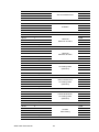
Contents
Chapter
1
Product Overview ................................1
1.1
1.2
1.5
1.6
1.7
1.8
Introduction ............................................................................................... 2
Feature Highlights ..................................................................................... 2
1.2.1 RESTful Web Service ................................................................... 2
1.2.2 Data Storage Function .................................................................. 3
1.2.3 IoT Cloud Function........................................................................ 3
Series Family and Specifications ............................................................. 4
1.3.1 Series Family ................................................................................ 4
Mechanical Design and Dimensions ......................................................... 5
1.4.1 WISE-4000 Wireless Series Dimensions...................................... 5
1.4.2 WISE-4000/LAN Dimensions........................................................ 5
Switch........................................................................................................ 6
LED Definition ........................................................................................... 6
Certification and Safety Standard ............................................................. 7
Package Information ................................................................................. 7
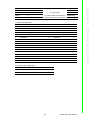
2
Product Specifications........................9
2.1
2.2
General Specification .............................................................................. 10
WISE-4010/LAN...................................................................................... 12
2.2.1 I/O Specification.......................................................................... 12
2.2.2 Application Wiring ....................................................................... 13
Figure 2.1 WISE-4010/LAN Current Input Wiring Diagram ....... 13
Figure 2.2 WISE-4010/LAN Digital Output Wiring Diagram....... 13
2.2.3 Pin Assignment ........................................................................... 14
Figure 2.3 WISE-4010/LAN Pin Assignment ............................. 14
2.2.4 Block Diagram............................................................................. 14
Figure 2.4 WISE-4010/LAN Block Diagram............................... 14
WISE-4050/LAN...................................................................................... 14
2.3.1 I/O Specification.......................................................................... 14
2.3.2 Application Wiring ....................................................................... 15
Figure 2.5 WISE-4050/LAN Digital Input Wiring Diagram ......... 15
Figure 2.6 WISE-4050/LAN Digital Output Wiring Diagram....... 15
2.3.3 Pin Assignment ........................................................................... 16
Figure 2.7 WISE-4050/LAN Pin Assignment ............................. 16
2.3.4 Block Diagram............................................................................. 16
Figure 2.8 WISE-4050/LAN Block Diagram............................... 16
WISE-4060/LAN...................................................................................... 17
2.4.1 I/O Specification.......................................................................... 17
2.4.2 Application Wiring ....................................................................... 18
Figure 2.9 WISE-4060/LAN Digital Input Wiring Diagram ......... 18
Figure 2.10WISE-4060/LAN Relay Output Wiring Diagram ....... 18
2.4.3 Pin Assignment ........................................................................... 19
Figure 2.11WISE-4060/LAN Pin Assignment ............................. 19
2.4.4 Block Diagram............................................................................. 19
Figure 2.12WISE-4060/LAN Block Diagram............................... 19
WISE-4012E ........................................................................................... 20
2.5.1 I/O Specification.......................................................................... 20
2.5.2 Application Wiring ....................................................................... 21
Figure 2.13WISE-4012E Voltage Input Wiring Diagram............. 21
1.3
1.4
Chapter
2.3
2.4
2.5
v
WISE-4000 User Manual
2.6
2.7
Chapter
3
Hardware Installation........................ 29
3.1
3.2
Interface Introduction .............................................................................. 30
Mounting ................................................................................................. 30
3.2.1 DIN-Rail Mounting ...................................................................... 30
Figure 3.1 Mounting Kit Back View............................................ 30
Figure 3.2 Installing the Mounting Kit for a DIN-Rail ................. 30
Figure 3.3 Mounting on the DIN-Rail ......................................... 31
Figure 3.4 Rear View of DIN-Rail Mounting .............................. 31
3.2.2 Wall Mounting ............................................................................. 31
Figure 3.5 Mounting Kit Dimensions.......................................... 32
Figure 3.6 Wall Mounting........................................................... 32
Figure 3.7 Wall Mounting Finished ............................................ 33
3.2.3 Stack Mounting ........................................................................... 33
Figure 3.8 Stack Mounting......................................................... 33
Figure 3.9 Finished Stack Mounting .......................................... 34
Wiring & Connections ............................................................................. 35
3.3.1 Power Supply Wiring .................................................................. 35
3.3.2 I/O Units...................................................................................... 35
3.3
Chapter
Figure 2.14WISE-4012E Digital Input Wiring Diagram............... 21
Figure 2.15WISE-4012E Relay Output Wiring Diagram............. 22
2.5.3 Pin Assignment........................................................................... 22
Figure 2.16WISE-4012E Pin Assignment................................... 22
2.5.4 Block Diagram ............................................................................ 22
Figure 2.17WISE-4012E Block Diagram .................................... 22
WISE-4050.............................................................................................. 23
2.6.1 I/O Specification.......................................................................... 23
2.6.2 Application Wiring ....................................................................... 24
Figure 2.18WISE-4050 Digital Input Wiring Diagram ................. 24
Figure 2.19WISE-4050 Digital Output Wiring Diagram .............. 24
2.6.3 Pin Assignment........................................................................... 24
Figure 2.20WISE-4050 Pin Assignment ..................................... 24
2.6.4 Block Diagram ............................................................................ 25
Figure 2.21WISE-4050 Block Diagram....................................... 25
WISE-4060.............................................................................................. 26
2.7.1 I/O Specification.......................................................................... 26
2.7.2 Application Wiring ....................................................................... 27
Figure 2.22WISE-4060 Digital Input Wiring Diagram ................. 27
Figure 2.23WISE-4060 Relay Output Wiring Diagram ............... 27
2.7.3 Pin Assignment........................................................................... 27
Figure 2.24WISE-4060 Pin Assignment ..................................... 27
2.7.4 Block Diagram ............................................................................ 28
Figure 2.25WISE-4060 Block Diagram....................................... 28
4
System Configuration....................... 37
4.1
4.2
Connection.............................................................................................. 38
Configure WISE Using the Web Interface............................................... 38
4.2.1 System Requirements ................................................................ 38
4.2.2 List of WISE-4000 Default Ethernet Ports .................................. 38
4.2.3 Factory Default Settings ............................................................. 39
4.2.4 Module Authorization .................................................................. 39
4.2.5 Operation Mode .......................................................................... 39
4.2.6 Using a Browser to Configure the Module .................................. 40
WISE-4000 User Manual
vi
4.3
4.4
Configure WISE-4000 with ADAM.NET Utility ........................................ 53
4.3.1 Operation Framework ................................................................. 53
Configuring WISE-4000 with ADAM.NET Utility (software)..................... 57
Appendix A
I/O Modbus Mapping Table ...............61
A.1
A.2
A.3
A.4
Modbus Function Code Introduction ....................................................... 62
WISE-4010/LAN Modbus Mapping Table ............................................... 62
WISE-4050/LAN Modbus Mapping Table .........................................................66
WISE-4060/LAN Modbus Mapping Table .........................................................68
Appendix B
REST for WISE-4000 ..........................71
B.1
B.2
Introduction ............................................................................................. 72
REST Resources for WISE-4000............................................................ 73
B.2.1 Digital Input ................................................................................. 73
B.2.2 Digital Output .............................................................................. 78
B.2.3 Analog Input................................................................................ 83
vii
WISE-4000 User Manual
WISE-4000 User Manual
viii
Chapter
1
Product Overview
1
1.1 Introduction
WISE-4000 series is an Ethernet-based wired or wireless IoT device, which integrated with IoT data acquisition, processing, and publishing functions. Except various
I/O type offering, WISE-4000 series provides data pre-scaling, data logic, and data
logger functions. These data can be access via mobile devices and be published to
cloud with security in anytime and anywhere.
1.2 Feature Highlights
1.2.1 RESTful Web Service
Integrated with HTML5, JavaScript, and RESTful web service which satisfy the
needs of IT technology, and also open a new market for WISE-4000 I/O module.
WISE-4000 will not only sell to automation SI, but also the SI who has high level programming skill and network integration abilities
WISE-4000 User Manual
2
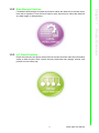
File-based cloud storage and data log function makes the data can be access at any
time and in anywhere. User will never need to care about how to collect the data into
any data logger or data gateway..
Chapter 1
1.2.2 Data Storage Function
Product Overview
1.2.3 IoT Cloud Function
Direct cloud access and direct mobile devices access functions make the information
easier to been access. With 3-levels security, these data can storage, access, and
publish in more safety way.
3
WISE-4000 User Manual
1.3
Series Family and Specifications
1.3.1
Series Family
Interface
WLAN
LAN
Model
Description
WISE-4012E
6-ch Universal Input or Output
Wireless IoT Ethernet I/O Module for IoT Developer
WISE-4050
4-ch Digital Input and 4-ch Digital Output
Wireless IoT Ethernet I/O Module
WISE-4060
4-ch Digital Input and 4-ch Relay Output
Wireless IoT Ethernet I/O Module
WISE-4010/LAN
4-ch Current Input and 4-ch Digital Output
IoT Ethernet I/O Module
WISE-4050/LAN
4-ch Digital Input and 4-ch Digital Output
IoT Ethernet I/O Module
WISE-4060/LAN
4-ch Digital Input and 4-ch Relay Output
IoT Ethernet I/O Module
WISE-4000 User Manual
4
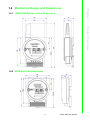
1.4.1
WISE-4000 Wireless Series Dimensions
Chapter 1
1.4 Mechanical Design and Dimensions
Product Overview
1.4.2 WISE-4000/LAN Dimensions
5
WISE-4000 User Manual
1.5 Switch
Switch
Description
SW1
Operation Mode
SW2
DI Type
(all channels)
Position
ON (Default)
OFF
P1
Normal Mode
Initial Mode
P2
N/A
N/A
P1
Dry Contact
Wet Contact
P2
Dry Contact
Wet Contact
Note 1 After the position 1 of SW1 been changed, user need to power on the
module again to apply the operation mode
Note 2 SW2 in only for WISE-4050(/LAN) and WISE-4060(/LAN), all 4 channels
have to be configured to dry contact or wet contact in the same time, and
both P1 and P2 have to be changed together
1.6 LED Definition
WISE-4000 Wireless Series
LED
Color
Status
Green
Com
Yellow
AP/Station
Green
Signal
Strength
Green
Indication
Behavior
Blink
Module is normally at work. (1Hz)
ON 30 Sec
When enable LOCATE function.
Blink
When TX/RX data in transmission
ON
Limited AP Mode
OFF
Station Mode
ON *4
Full Signal
ON *3
Good Signal
ON *2
Okay Signal
ON *1
Poor Signal
All OFF
No Signal
WISE-4000/LAN Series
LED
Color
Status
Green
Com
Indication
Behavior
Blink
Module is normally at work. (1Hz)
ON 30 Sec
When enable LOCATE function.
Yellow
Blink
When TX/RX data in transmission
Link
Green
ON
Ethernet cable is connected
Speed
Yellow
ON/OFF
ON: 100 Mbps
OFF: Less than 100 Mbps
WISE-4000 User Manual
6
FCC
– FCC 47 CFR PART 15 (Class A)
– IC ICES-003
CE
– EN 55011 / 55022 (Class A)
– EN 61000-6-4
– EN 61000-3-2
– EN 61000-3-3
– EN 55024
– EN 61000-6-2
– IEC 61000-4-2
– IEC 61000-4-3
– IEC 61000-4-4
– IEC 61000-4-5
– IEC 61000-4-6
– IEC 61000-4-8
– IEC 61000-4-11
– RoHS
China RoHS
WEEE
Product Overview
Chapter 1
1.7 Certification and Safety Standard
1.8 Package Information
WISE-4000 Wireless Series
WISE-4000 Module with bundle antenna and terminal connector x1
Mounting bracket x1
Quick startup manual with China RoHS declare
WISE-4000/LAN Series
WISE-4000/LAN Module
Mounting bracket x1
Quick startup manual with China RoHS declare
WISE-4012E
WISE-4012E Module with bundle antenna and terminal connector x1
Quick startup manual with China RoHS declare
USB drive with WebAccess
USB power cable
Extension board
Screwdriver
7
WISE-4000 User Manual
WISE-4000 User Manual
8
Chapter
2
2
Product Specifications
2.1 General Specification
WLAN Interface
Standard Conformance:
– 802.11b
– 802.11g
– 802.11n
Network Modes:
– Limited AP (Wireless Server)
– Station/Infrastructure (Wireless Client)
LAN Interface
Ethernet: IEEE 802.3u 10/100Base-T(X)
Connector: 1-port RJ-45
General
Connector: 3.5mm spacing, 15-pole, plug-in screw terminal block (I/O and
power)
Watchdog Timer
– System: 1.6 second
– Communication
– Programmable (FSV)
Enclosure: PC
Mounting: DIN 35 rail, wall, and stack
Dimensions (W x H x D)
– With bundle antenna
– Without bundled antenna: 80 x 89 x 25 mm
Operation Temperature:
– WISE-4000 Wireless Series: -25~70°C (-13~158°F)
– WISE-4000/LAN Series: -40~70°C (-40~158°F)
Storage Temperature: -40~85°C (-40~185°F)
Operating Humidity: 20~ 95% RH (non-condensing)
Storage Humidity: 0~95% RH (non-condensing)
Note!
Equipment will operate below 30% humidity. However, static electricity
problems occur much more frequently at lower humidity levels. Make
sure you take adequate precautions when you touch the equipment.
Consider using ground straps, anti-static floor coverings, etc. if you use
the equipment in low humidity environments.
WISE-4000 User Manual
10
Chapter 2
Power
Power Input Voltage:
10~30 VDC (24 VDC Standard)
– WISE-4012E
Power Consumption
– WISE-4012E: 2.2 W @ 5 VDC
– WISE-4050: 2.2 W @ 24 VDC
– WISE-4060: 2.5 W @ 24 VDC
– WISE-4010/LAN: 1.2 W @ 24 VDC
– WISE-4050/LAN: 2.2 W @ 24 VDC
– WISE-4060/LAN: 2.5 W @ 24 VDC
Power Protection
Software
Configuration Interface: Web Interface, Windows Utility
Utility: ADAM/Apax .NET Utility
Library API (Driver): ADAM .NET Class Library
Industrial Protocol: Modbus/TCP
Supported Protocols: TCP/IP, UDP, HTTP, HTTPS, DHCP, ARP, SNTP
Supported Web Functions: RESTful, HTML5, JavaScript, JSON
11
WISE-4000 User Manual
Product Specifications
– WISE-4050
– WISE-4060
– WISE-4010/LAN
– WISE-4050/LAN
– WISE-4060/LAN
USB 5VDC ±10%
2.2 WISE-4010/LAN
2.2.1 I/O Specification
Current Input
– Channel: 4
– Resolution: 12-bit
– Sampling Rate: 10/100 Hz/channel
– Accuracy: ±0.2% of FSR @ 25°C
– Input Range: 0~20 mA, 4~20 mA (Select by Web Configuration)
– Input Impedance: 120 Ω
– Burn-out Detection: Yes (4~20 mA only)
– Supports Data Scaling and Averaging
Digital Output
– Channels: 4
–Open collector to 30 V, 500 mA max. for resistance load
–Inductive loads require an external diode to eliminate back-EMF when the
DO is turned off
– On Resistance (RDS(ON)): 0.3 Ω (max.) @ 500mA, 25°C
– Supports 1 kHz Pules Output
– Supports High-to-Low and Low-to-High Delay Output
WISE-4000 User Manual
12
Chapter 2
2.2.2 Application Wiring
Figure 2.2 WISE-4010/LAN Digital Output Wiring Diagram
13
WISE-4000 User Manual
Product Specifications
Figure 2.1 WISE-4010/LAN Current Input Wiring Diagram
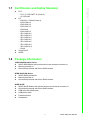
2.2.3 Pin Assignment
Figure 2.3 WISE-4010/LAN Pin Assignment
2.2.4 Block Diagram
Figure 2.4 WISE-4010/LAN Block Diagram
2.3 WISE-4050/LAN
2.3.1 I/O Specification
Digital Input
– Channel: 4
– Logic level
–Dry Contact 0: Open
1: Close to DI COM
–Wet Contact 0: 0~3 VDC (0.8 mA max.)
1: 10~30 VDC (3 mA min.)
–All 4 channels should be configured to dry contact or wet contact in the
same time
– Isolation: 3,000 Vrms
–
–
–
–
Supports 3 kHz Counter Input (32-bit + 1-bit overflow)
Keep/Discard Counter Value when Power-off
Supports 3 kHz Frequency Input
Supports Inverted DI Status
WISE-4000 User Manual
14
Digital Output
– Channels: 4
– Open collector to 30 V, 500 mA max. for resistance load
– Inductive loads require an external diode to eliminate back-EMF when the
DO is turned off
– Isolation: 3,000 Vrms
– On Resistance (RDS(ON)): 0.3 Ω (max.) @ 500mA, 25°C
Product Specifications
– Supports 1 kHz Pules Output
– Supports High-to-Low and Low-to-High Delay Output
2.3.2 Application Wiring
Figure 2.5 WISE-4050/LAN Digital Input Wiring Diagram
Figure 2.6 WISE-4050/LAN Digital Output Wiring Diagram
15
Chapter 2
WISE-4000 User Manual
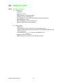
2.3.3 Pin Assignment
Figure 2.7 WISE-4050/LAN Pin Assignment
2.3.4 Block Diagram
Figure 2.8 WISE-4050/LAN Block Diagram
WISE-4000 User Manual
16
Chapter 2
2.4 WISE-4060/LAN
2.4.1 I/O Specification
Product Specifications
Digital Input
– Channel: 4
– Logic level
– Dry Contact 0: Open
1: Close to DI COM
– Wet Contact 0: 0~3 VDC (0.8 mA max.)
1: 10~30 VDC (3 mA min.)
– Isolation: 3,000 Vrms
–
–
–
–
Supports 3 kHz Counter Input (32-bit + 1-bit overflow)
Keep/Discard Counter Value when Power-off
Supports 3 kHz Frequency Input
Supports Inverted DI Status
Relay Output
– Channels: 4 (Form A)
– Contact Rating
–250 VAC @ 5 A
–30 VDC @ 3 A
– Relay On Time: 10 ms
– Relay Off Time: 5 ms
– Insulation Resistance: 1 GΩ min. @ 500 VDC
– Dielectric Strength
–Between Contacts: 1000 VAC (1min)
–Between Coil to Contact: 3000 VAC (1min)
– Maximum Switching: 60 operations/minute
– Supports Pules Output
– Supports High-to-Low and Low-to-High Delay Output
17
WISE-4000 User Manual
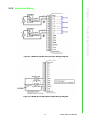
2.4.2 Application Wiring
Figure 2.9 WISE-4060/LAN Digital Input Wiring Diagram
Figure 2.10 WISE-4060/LAN Relay Output Wiring Diagram
WISE-4000 User Manual
18
Chapter 2
2.4.3 Pin Assignment
Figure 2.11 WISE-4060/LAN Pin Assignment
Product Specifications
2.4.4 Block Diagram
Figure 2.12 WISE-4060/LAN Block Diagram
19
WISE-4000 User Manual
2.5 WISE-4012E
2.5.1 I/O Specification
Voltage Input
– Channel: 2
– Resolution: 12-bit
– Sampling Rate: 10 Hz (Total)
– Accuracy: ±0.1 VDC
– Input Range: 0~10 VDC
– Input Impedance: 100 kΩ
– Supports Data Scaling and Averaging
Digital Input
– Channel: 2
– Logic level
–Dry Contact 0: Open
1: Close to GND
– Supports 3 kHz Counter Input (32-bit + 1-bit overflow)
– Keep/Discard Counter Value when Power-off
– Supports 3 kHz Frequency Input
– Supports Inverted DI Status
Relay Output
– Channels: 2 (Form A)
– Contact Rating
–120 VAC @ 0.5 A
–30 VDC @ 1A
– Isolation: 500Vrms
– Relay On Time: 5 ms
– Relay Off Time: 6 ms
– Insulation Resistance: 1 GΩ min. @ 500 VDC
– Maximum Switching: 60 operations/minute
– Supports Pules Output
– Supports High-to-Low and Low-to-High Delay Output
WISE-4000 User Manual
20
Chapter 2
2.5.2 Application Wiring
Figure 2.14 WISE-4012E Digital Input Wiring Diagram
21
WISE-4000 User Manual
Product Specifications
Figure 2.13 WISE-4012E Voltage Input Wiring Diagram
Figure 2.15 WISE-4012E Relay Output Wiring Diagram
2.5.3 Pin Assignment
Figure 2.16 WISE-4012E Pin Assignment
2.5.4 Block Diagram
Figure 2.17 WISE-4012E Block Diagram
WISE-4000 User Manual
22
Chapter 2
2.6 WISE-4050
2.6.1 I/O Specification
–All 4 channels should be configured to dry contact or wet contact in the
same time
– Isolation: 3,000 Vrms
–
–
–
–
Supports 3 kHz Counter Input (32-bit + 1-bit overflow)
Keep/Discard Counter Value when Power-off
Supports 3 kHz Frequency Input
Supports Inverted DI Status
Digital Output
– Channels: 4 (Open collector to 30 V, 500 mA max. for resistance load)
– Isolation: 3,000 Vrms
– On Resistance (RDS(ON)): 0.3 Ω (max.) @ 500mA, 25°C
– Supports 1 kHz Pules Output
– Supports High-to-Low and Low-to-High Delay Output
23
WISE-4000 User Manual
Product Specifications
Digital Input
– Channel: 4
– Logic level
–Dry Contact 0: Open
1: Close to DI COM
–Wet Contact 0: 0~3 VDC (0.8 mA max.)
1: 10~30 VDC (3 mA min.)
2.6.2 Application Wiring
Figure 2.18 WISE-4050 Digital Input Wiring Diagram
Figure 2.19 WISE-4050 Digital Output Wiring Diagram
2.6.3 Pin Assignment
Figure 2.20 WISE-4050 Pin Assignment
WISE-4000 User Manual
24
Chapter 2
2.6.4 Block Diagram
25
WISE-4000 User Manual
Product Specifications
Figure 2.21 WISE-4050 Block Diagram
2.7 WISE-4060
2.7.1 I/O Specification
Digital Input
– Channel: 4
– Logic level
–Dry Contact 0: Open
1: Close to DI COM
–Wet Contact 0: 0~3 VDC (0.8 mA max.)
1: 10~30 VDC (3 mA min.)
– Isolation: 3,000 Vrms
– Supports 3 kHz Counter Input (32-bit + 1-bit overflow)
– Keep/Discard Counter Value when Power-off
– Supports 3 kHz Frequency Input
– Supports Inverted DI Status
Relay Output
– Channels: 4 (Form A)
– Contact Rating
–250 VAC @ 5 A
–30 VDC @ 3 A
– Relay On Time: 10 ms
– Relay Off Time: 5 ms
– Insulation Resistance: 1 GΩ min. @ 500 VDC
– Dielectric Strength
–Between Contacts: 1000 VAC (1min)
–Between Coil to Contact: 3000 VAC (1min)
– Maximum Switching: 60 operations/minute
– Supports Pules Output
– Supports High-to-Low and Low-to-High Delay Output
WISE-4000 User Manual
26
Chapter 2
2.7.2 Application Wiring
Figure 2.23 WISE-4060 Relay Output Wiring Diagram
2.7.3 Pin Assignment
Figure 2.24 WISE-4060 Pin Assignment
27
WISE-4000 User Manual
Product Specifications
Figure 2.22 WISE-4060 Digital Input Wiring Diagram
2.7.4 Block Diagram
Figure 2.25 WISE-4060 Block Diagram
WISE-4000 User Manual
28
Chapter
3
3
Hardware Installation
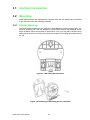
3.1 Interface Introduction
3.2 Mounting
WISE-4000 modules are designed as compact units and are allowed to be installed
in the field site under the following methods.
3.2.1 DIN-Rail Mounting
The WISE-4000 module can also be fixed to the cabinet by using mounting rails. You
need to assemble the DIN rail adapter to WISE-4000 module with flathead screw
driver as below. When the module is mounted on a rail, you may also consider using
end brackets at each end of the rail to keep the module from sliding horizontally along
the rail.
Figure 3.1 Mounting Kit Back View
Figure 3.2 Installing the Mounting Kit for a DIN-Rail
WISE-4000 User Manual
30
Chapter 3
Hardware Installation
Figure 3.3 Mounting on the DIN-Rail
Figure 3.4 Rear View of DIN-Rail Mounting
3.2.2 Wall Mounting
Each WISE-4000 module is packed with a plastic wall mounting bracket. User can
refer the bracket dimension and assembling figure to configure an optimal placement
in a wall, panel, or cabinet.
31
WISE-4000 User Manual
Figure 3.5 Mounting Kit Dimensions
Figure 3.6 Wall Mounting
WISE-4000 User Manual
32
Chapter 3
Hardware Installation
Figure 3.7 Wall Mounting Finished
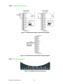
3.2.3 Stack Mounting
Figure 3.8 Stack Mounting
33
WISE-4000 User Manual
Figure 3.9 Finished Stack Mounting
WISE-4000 User Manual
34
This section introduces basic information on wiring the power supply, I/O units, and
Ethernet connection.
3.3.1 Power Supply Wiring
Screw terminals +Vs and -Vs are for power supply wiring
Note!
The wires used should be at least 2 mm.
3.3.2 I/O Units
The system uses a plug-in screw terminal block for the interface between I/O modules and field devices. The following information must be considered when connecting electrical devices to I/O modules.
1. The terminal block accepts wires from 0.5 mm to 2.5 mm.
2. Always use a continuous length of wire. Do not combine wires.
3. Use the shortest possible wire length.
4. Use wire trays for routing where possible.
5. Avoid running wires near high-energy wiring.
6. Avoid running input wiring in close proximity to output wiring.
7. Avoid creating sharp bends in the wires.
35
WISE-4000 User Manual
Hardware Installation
The system of WISE- 4000 is designed for a standard industrial unregulated 24 VDC
power supply. For further application, it can also accept +10 to +30 VDC of power
input, 200mV peak to peak of power ripple, and the immediate ripple voltage should
be maintained between +10 and +30 VDC.
Chapter 3
3.3 Wiring & Connections
WISE-4000 User Manual
36
Chapter
4
4
System Configuration
4.1 Connection
1.
2.
Plug DC power source in +Vs, -Vs pin of WISE module and turn the power on.
Connect your computer to Ethernet port of WISE module with RJ-45 cross-over
Ethernet cable)
4.2 Configure WISE Using the Web Interface
4.2.1 System Requirements
module is developed by public HTML 5 base, but for detailed indication and data
transmission mode may be different on Web page of the operating system.
For mobile devices, the minimum requirement of web browsers as below:
Safari 6 in Apple iOS
Web Browser in Google Android 4.0 (Ice Cream Sandwich)
Chrome in Google Android 4.0 (Ice Cream Sandwich)
Mobile Browse
Chrome
Android
Safari
Configuration
Y
Y
Y
File Upload
N
N
N
Data Log Chart
Y
Y
Y
Data Log Export
N
N
N
For PC platforms, the minimum requirement of web browsers as below:
Internet Explorer (version 11)
Google Chrome (version 30)
Mozilla Firefox (version 25)
Mobile Browse
4.2.2
Chrome Firefox
Safari
IE11
IE10
IE9
Configuration
Y
Y
Y
Y
Y
Y
File Upload
Y
Y
N
Y
N
N
Data Log Chart
Y
Y
Y
Y
Y
N
Data Log Export
Y
Y
N
N
N
N
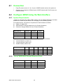
List of WISE-4000 Default Ethernet Ports
Application
Protocol
Port
Note
WebServer
TCP
80
Configurable
Modbus Server
TCP
502
-
Search Engine
UDP
5048
-
SNTP Client
UDP
-
Randomly
WISE-4000 User Manual
38
Chapter 4
4.2.3 Factory Default Settings
WISE-4000/LAN Series
IP Mode: Static IP Address
Default IP: 10.0.0.1
Subnet Mask: 255.0.0.0
Default Gateway: 0.0.0.0
Default Connection Timeout: 720 second
HTTP Port: 80
Account
Default Password
Access Ability
Root
00000000
All the privileges
Admin
00000000
All the privileges except access control configuration
User
00000000
View module status only, not allow to do configuration
4.2.5 Operation Mode
The operation mode can be configured by SW1 on the back of module. Please refer
to previous chapter for the detail of configuring SW1.
Mode
WISE-4000/LAN Series
WISE-4000 Wireless Series
Initial Mode
Fixed IP address: 10.0.0.1
Fixed IP address: 192.168.1.1
Fixed Wi-Fi Mode: AP Mode
Normal Mode
Default IP address: 10.0.0.1
Default IP address: 192.168.1.1
Default Wi-Fi Mode: AP Mode
39
WISE-4000 User Manual
System Configuration
4.2.4 Module Authorization
4.2.6
Using a Browser to Configure the Module
Configure URL: http://IP_address/config
Default URL: http://10.0.0.1/config
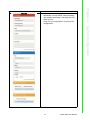
Configuration Steps
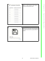
Login Web Configuration Page
1.
2.
3.
WISE-4000 User Manual
Wirelessly connect your smart phone
to your local Ethernet network and
open the browser of your smart
phone.
Enter IP address of module with "/
config", for example, the default URL:
http://10.0.0.1/config
Then you will see the login page,
please enter the account and password, then click Login button
4.
After login you will see the configuration web page
5.
Scroll down the tab, you can change
the login user here
6.
Click the button on the top, you can
switch to other pages
40
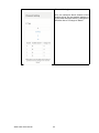
1.
2.
In the information page, you can see the
dashboard: module detail, network setting,
and module information, including the firmware version.
Click "Go to Configuration” to perform the
configuration.
Chapter 4
Module Information
System Configuration
41
WISE-4000 User Manual
Module Configuration
You can click different tab to switch the
item you are going to configure
[Information]
Customized Name / UUID
Means model name and UUID of the module. You also can rename it for recognition
if required.
Description
You can add comments on this module for
recognition.
Location Information
You can note the location information for
the module
WISE-4000 User Manual
42
You can select the Connection mode as
DHCP or Static IP and configure the IP
address, Subnet address, and Default
gateway.
You configure the web server port, Host
Idle (timeout), and decide whether to
enable communication WDT here
[Time & Date]
You can see the current time here, decide
which time zone for your local time, and
also do the time calibration by read the
time from host devices
43
WISE-4000 User Manual
System Configuration
[Network App]
Chapter 4
[Network]
[SNTP]
You can enable the SNTP function, so the
module can act as a SNTP client to do
time synchronization from assigned SNTP
server.
[Modbus]
In order to provide user with more flexible
and scalable in deploying module, this
module remove the limitation of Modbus
address setting and make it configurable
as user's actual need. Basically, there're
two kinds of Modbus address section (0X
and 4X) for you to configure each function
item.
WISE-4000 User Manual
44
Here you can know the status of this module
Enable Locate
It can help user search module with light
sign. (Status LED will be constantly on for
10 sec when it enabled.)
Restore to Default
The system configuration of module will
be clear and restored to factory default
when it enabled.
Reset Password
You can reset the password here
System Restart
The system of this module will reboot
when it enabled.
[General]
After Communication WDT been enabled
in "Network App" tab, you can enable the
IO FSV triggered by communication WDT
[Firmware]
You can upgrade the firmware and html file
here
45
WISE-4000 User Manual
System Configuration
[Control]
Chapter 4
[Diagnostic]
[Account]
You can change the passwords of each
account here.
I/O Status
[Status]
The I/O statuses are shown here, for the
output status, you can also change the I/O
status here.
WISE-4000 User Manual
46
Setting
User can do detail I/O setting in the tab,
include the Tag Name, range type, filter,
and also the working mode.
Overview
In the end, there is an overview table for
the configuration summary of each channel
47
WISE-4000 User Manual
System Configuration
Calibration
For the analog module, after login root
account, user can click calibration button
to restore the factory calibration value.
Chapter 4
[Configuration]
[Trend]
The status trend of I/O will be shown here.
Advanced Function - Access Control
To avoid unauthorized access, you can
manage which host PC or device can
remotely control the WISE-4000 module
by IP or MAC Address.
WISE-4000 User Manual
48
The WISE-4000 series supports data log
functions, the I/O status can be logged in
the module and also be queried from the
module .
49
WISE-4000 User Manual
System Configuration
Advance Function - Data Log
Chapter 4
Enable one of the rows and enter the IP
address or MAC address which allows to
access the WISE-4000 device.
[Viewer]
Data Format
User can configure which data will be logger and the timestamp format here
Filter
This filter is for setting the criteria to query
the logged data. User can select the filter
mode and click “Query” button to query the
logged data
After the “Query” has been clicked, the
data will be shown in the dashboard and
also in the list. Users can click the “Save”
button to save the logged data.
WISE-4000 User Manual
50
Period Interval
Decide the logging period if “Periodical
Log” had been enabled. Pleased been
noted that the period is increased by 0.1
sec, it means if user configure “600” here,
the status of the I/O will be logged each
minute.
WDT Trigger
If the communication WDT been enable,
once the condition of WDT been met, the
status of I/O will be logged
Reset the Log on Restart
Decided whether to keep last value when
the logger had been restarted.
Circular Operation
Once the box been check, the data will
been circular log when memory was full.
Otherwise, the logger will stop.
51
WISE-4000 User Manual
System Configuration
Periodical Log
Check the box to enable periodically logging, and the log period can be decided in
“Period Interval” box
Chapter 4
[General Settings]
I/O Data Logger
Decide whether to enable data log function
here
[Channel Setting]
User can configure which channel of the
module will be log and decide whether to
log the data when the status is changed by
check the box of “Change of Status”
WISE-4000 User Manual
52
Install ADAM.NET Utility in your computer.
(After successfully installation, there will be a shortcut generated on the screen)
2.
3.
Double click the shortcut icon, and then you will see the main operation window.
Click Search Module icon in Toolbar. You will see all online modules in the left
Module Tree screen and an unconfigured new module, whose default password
is 00000000, will appear on the Others section as below. Now you can define
the network mode of the module in the beginning. After that, you will be able to
perform other settings.
Note!
The default password is 00000000
4.3.1 Operation Framework
The operation window mainly contains 4 areas, including Menu, Toolbar, Module
Tree screen and Main Operation screen.
4.3.1.1 Menu
a. File
Open Favorite Group
You can import the favorite configuration group file (.XML) from your computer.
Save Favorite Group
You can save the favorite group configuration group as XML file to your computer.
Auto-Initial Group
If you want to have the same favorite group configuration when you exit
ADAM.NET utility and launch it again, you need to check this option.
Exit
Exit ADAM.NET Utility.
53
WISE-4000 User Manual
System Configuration
1.
Chapter 4
4.3 Configure WISE-4000 with ADAM.NET Utility
b. Tools
Search Device
Search all the WISE-4000 modules you connected in local Ethernet.
Add Devices to Group
It's used to add WISE-4000 modules to your favorite group. After activating
search function, all online modules will show on Module Tree Screen area. Now
you can enable this function to select the device you want to add in the Module
Tree Screen.
Group Configuration
Group Configuration is on WISE-4000 series module. It can help you efficiently
configure or maintain massive WISE-4000 modules with the same configuration
file or firmware upgrade at one time in the local network. The following steps will
instruct you how to operate it.
Terminal for Command Testing
WISE-4000 series module Modbus/TCP as communication protocol, so you can
launch the terminal to directly communicate with WISE-4000 series module by
these two protocols.
Print Screen
You can save current ADAM.NET Utility screen into an image file by this option.
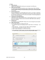
HTML File Packager
You can pack your user web page by this tool:
1. Put all the files that you are going to pack in same folder, and “Browse…” the
folder
2. Press “Save as…” and give a file name after it’s been packaged
3. Check all the files had been selected in “File List”
4. Check “Gzip Compression” to reduce the file size
5. After pressing the “Apply” button, your user web page will be compressed as
a “*.ehf” file, then you can download the file into your WISE module
WISE-4000 User Manual
54
55
WISE-4000 User Manual
System Configuration
d. Help
Check Up-to-Date on the Web
It will automatically connect to support and download page of Advantech website when it enabled. You can find and download the latest version of WISE4000 utility there.
About ADAM.NET Utility
The current version of ADAM.NET Utility is installed on your computer.
Chapter 4
c. Setup
Favorite Group
You can configure your favorite group including add one new device, modify or
delete one current device, sort current devices and diagnose connection to one
device.
Refresh Serial and Ethernet
ADAM.NET utility will refresh the serial and LAN network connection situation.
Add COM Ports
This option is used to add serial COM ports in ADAM.NET Utility. You won't
need to use this option for WISE-4000 modules.
Show TreeView
Check this option to display the Module Tree Screen area.
Allow Calibration
Check this option to allow calibration function enabled on AI/O module.
4.3.1.2 Toolbar
There are 8 graphical icons for common used options of Menu on the toolbar.
Definition (from left to right)
1. Open favorite group
2. Save favorite group
3. Search Modules
4. Add Devices to Group
5. Terminal for Command Testing
6. Group Configuration
7. Monitor Data Stream/Event
8. Print Screen
4.3.1.3 Module Tree Screen
The Module Tree Screen locates on the left part of ADAM.NET utility operation window. There are four categories in this area:
Serial
All serial I/O Modules (ADAM-4000 and ADAM-5000 RS-485 serial modules) connected to the host PC will be listed in this category.
Ethernet
All Ethernet I/O Modules (ADAM-6000, ADAM-6100,and ADAM-5000 TCP modules)
connected to the host PC will be listed in this category.
Favorite Group
You can define which devices listed in the three categories above into your personal
favorite group. This will make you easier to find your interested modules. Right click
on the WISE-4000 device item under the Favorite Group item and you can select Add
New Group to create a new group. After you create your own group, right click on
your group and Add New Device into your group. You can also select Diagnose connection to check the communication.
ADAM-4500_5510 Series
This is a DOS interface utility for remote controllers such as ADAM-4500 and ADAM5510 series.
Wireless Sensor Networks
All wireless I/O Modules (ADAM-2000 modules) connected to the host PC, through
wireless gateway, will be listed in this category.
4.3.1.4 Main Operation Screen
Main Operation Screen located on the right side of utility includes I/O status display
and function setting. You can select different items in Module Tree Screen, and then
Main Operation Screen will change dependently. You can do all configurations and
test in this area.
In Information page (after clicking Ethernet), you can configure Connection/Send/
Receive/Scan Timeout. The supervisor password is a shortcut to let you enter a
password at one time which's applied for certain modules, so you don't need to enter
the same password for each module when you check it.
WISE-4000 User Manual
56
Note!
1.
2.
3.
Before installing ADAM.NET Utility, you need to install .NET
Framework 2.0 or higher version.
System requirement
– Microsoft Windows XP/7
– At least 32 MB RAM
– 20 MB of hard disk space available
– VGA color or higher resolution monitor
– Mouse or other pointing devices
– 10/100 Mbps or higher Ethernet Card
Configure the computer’s IP address as the same domain as WISE-4000 module. For the new WISE-4000/LAN Series which default IP address is 10.0.0.1,
the IP address of computer can be configured as 10.0.0.99 for example as following.
Open the Adam/Apax .NET Utility then you can see the IP address of computer
been shown under “Ethernet” tree. You can right click to refresh the subnodes of
this tree. Or click “Search Device” to find WISE-4000 module.
Users can also right click the IP address to find WISE-4000 module.
57
WISE-4000 User Manual
System Configuration
ADAM.NET Utility, which is designed with graphical operation interface, is aimed to
offer users directly configure, control WISE-4000 module, and monitor the real-time
status of remote WISE-4000 module via Ethernet or Wireless connection.
To keep you informed with latest update, you also can check it from the following
download link on Advantech website.
http://support.advantech.com.tw/Support/DownloadSRDetail.aspx?SR_ID=12AKUDB
Chapter 4
4.4 Configuring WISE-4000 with ADAM.NET Utility
(software)
4.
After the module been found, it will be listed under IP address in same domain,
you can login the embedded web configuration web page for further configuration as introduced in previous section
5.
There are some function provide in same pages in utility, first you can enter the
account and password faster in "Login Info" tab.
6.
In the "Device Info" tab, the detail information of this module will been shown
7.
The "QR" tab will generate the QR code of the web configuration web page for
mobile device to access the module. User can also click the QR code to open
the browser for further configuration.
WISE-4000 User Manual
58
59
WISE-4000 User Manual
System Configuration
If you are not able to search the module, you can configure the SW1
behind the module to initial mode. After power up and search the module in utility, user can find the module with default IP address, and the
device name will been shown in "Others" tree with (*) sign. So user can
change the device network setting in this page. Or try to locate the
device and also reset the password with same page. After the new network setting been apply, please configure the SW1 back to normal
mode and power up again to reboot in new network setting.
Chapter 4
Note!
WISE-4000 User Manual
60
Appendix
A
A
I/O Modbus Mapping
Table
A.1 Modbus Function Code Introduction
To full-fill the programming requirement, there is a series of function code standard
for user’s reference.
Code (Hex)
Name
Usage
01
Read Coil Status
Read Discrete Output Bit
02
Read Input Status
Read Discrete Input Bit
03
Read Holding Registers
04
Read Input Registers
Read 16-bit register. Used to read integer or
floating point process data.
05
Force Single Coil
Write data to force coil ON/OFF
06
Preset Single Register
Write data in 16-bit integer format
08
Loopback Diagnosis
Diagnostic testing of the communication port
0F
Force Multiple Coils
Write multiple data to force coil ON/OFF
10
Preset Multiple Registers
Write multiple data in 16-bit integer format
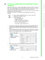
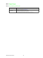
A.2 WISE-4010/LAN Modbus Mapping Table
Address (0X):
Address (0X)
Channel
00017
0
00018
1
00019
2
00020
3
Description
Attribute
Read/Write
DO Value
Read/Write
Read/Write
Read/Write
00101
0
Write
00102
1
Write
00103
2
00104
3
00105
Average Ch 0~3
Reset Historical
Maximum AI Value
Write
Write
Write
00111
0
Write
00112
1
Write
00113
2
00114
3
Write
00115
Average Ch 0~3
Write
00121
0
Read
00122
1
00123
2
00124
3
WISE-4000 User Manual
Reset Historical Min. AI Value
Open-Circuit Flag (Burnout)
Write
Read
Read
Read
62
0
Read
00132
1
00133
2
00134
3
Read
00135
Average Ch 0~3
Read
00141
0
Read
00142
1
Read
00143
2
00144
3
Read
00145
Average Ch 0~3
Read
Read
High Alarm Flag
Low Alarm Flag
Read
Read
Address (4X):
Address (4X)
Channel
Description
Attribute
40211
Module Name 1
Read
40212
Module Name 2
Read
40221
All AI
AI Channel Enabled
Read/Write
40303
All DO
DO Value
Read/Write
40001
0
Read
40002
1
Read
40003
2
AI Value
Read
40004
3
Read
40005
Average Ch 0~3
Read
40009-40010
0
Read/Write
40011~40012
1
40013~40014
2
40015~40016
3
Read/Write
40017-40018
0
Read/Write
40019~40020
1
40021~40022
2
40023~40024
3
Read/Write
40025-40026
0
Read/Write
40027~40028
1
40029~40030
2
40031~40032
3
Pulse Output
Low Level Width
Pulse Output
High Level Width
Set Absolute Pule
Read/Write
Read/Write
Read/Write
Read/Write
Read/Write
Read/Write
Read/Write
63
WISE-4000 User Manual
Appendix A I/O Modbus Mapping Table
00131
40033~40034
0
Read/Write
40035~40035
1
Read/Write
40037~40038
2
40037~40040
3
Read/Write
40101~40102
0
Read
40103~40104
1
40105~40106
2
40107~40108
3
Read
40111
0
Read
40112
1
40113
2
40114
3
40115
Average Ch 0~3
40121
0
Read
40122
1
Read
40123
2
40124
3
40125
Average Ch 0~3
Read
40131~40132
0
Read
40133~40134
1
40135~40136
2
40137~40138
3
40139~40140
Average Ch 0~3
Set Incremental Pulse
AI Status*
Historical
Maximum AI Value
Read/Write
Read
Read
Read
Read
Read
Read
Historical
Minimum AI Value
AI Floating Value
(IEEE754)
Read
Read
Read
Read
Read
Read
40151~40152
0
Read
40153~40154
1
Read
40155~40156
2
40157~40158
3
40159~40160
Average Ch 0~3
Read
40171~40172
0
Read
40173~40174
1
40175~40176
2
40177~40178
3
40179~40180
Average Ch 0~3
40191
0
Read
40192
1
Read
40193
2
40194
3
40195
Average Ch 0~3
WISE-4000 User Manual
Historical Maximum
AI Floating Value
(IEEE754)
Historical Minimum
AI Floating Value
(IEEE754)
Read
Read
Read
Read
Read
Read
AI Value
After Scaling
Read
Read
Read
64
0
40202
1
40203
2
Read/Write
Read/Write
AI Type Code**
40204
3
40205
Average Ch 0~3
Read/Write
(The type codes of channels for Read/Write
average value can't be changed.) Read
* AI Status (2 Registers)
Lower Register
Higher Register
Bit
Description
Bit
Description
0
Fail to Provide AI Value
0
DI triggered to Safety Value
1
Over Range
1
DI triggered to Startup Value
2
Under Range
2
Reserved
3
Open Circuit / Burnout
3
Reserved
4
Reserved
4
Reserved
5
Reserved
5
Reserved
6
Reserved
6
Reserved
7
ADC Initializing/Error
7
Reserved
8
Reserved
8
Reserved
9
Zero/Span Calibration Error
9
Reserved
10
Reserved
10
Reserved
11
Reserved
11
Reserved
12
Reserved
12
Reserved
13
Reserved
13
Reserved
14
Reserved
14
Reserved
15
Reserved
15
Reserved
** AI Type Code (2 Registers)
Type Code
Input Range
0x1080
4~20 mA
0x1082
0~20 mA
65
WISE-4000 User Manual
Appendix A I/O Modbus Mapping Table
40201
A.3 WISE-4050/LAN Modbus Mapping Table
Address 0X
Channel
00001
0
00002
1
00003
2
00004
3
Description
Attribute
Read
DI Value
Read
Read
Read
00017
0
Read/Write
00018
1
Read/Write
00019
2
00020
3
00033
0
00034
1
00035
2
00036
3
00037
0
00038
1
00039
2
00040
3
00041
0
00042
1
00043
2
00044
3
DO Value
Read/Write
Read/Write
Counter Status
(0: stop
1: start)
Read/Write
Read/Write
Read/Write
Read/Write
Write
Clear Counter
(1: write to clear value)
Write
Write
Write
Read/Write
Clear Overflow
(1: counter overflow,
auto set to 0 after read)
Read/Write
DI Latch Status
(1: DI latched,
0: write to clear latch)
Read/Write
Read/Write
Read/Write
Read/Write
00045
0
00046
1
00047
2
00048
3
Address 4X
Channel
40211
-
Module Name 1
Read
40212
-
Module Name 2
Read
40301
All DI
DI Value
Read
40303
All DO
DO Value
Read/Write
40001~40002
0
40003~40004
1
40005~40006
2
40007~40008
3
WISE-4000 User Manual
Description
Read/Write
Read/Write
Attribute
Read
Counter/Frequency
Value
Read
Read
Read
66
0
40011~40012
1
40013~40014
2
40015~40016
3
Read/Write
40017~40018
0
Read/Write
40019~40020
1
40021~40022
2
40023~40024
3
Read/Write
40025~40026
0
Read/Write
40027~40028
1
40029~40030
2
40031~40032
3
Pulse Output
Low Level Width
Pulse Output
High Level Width
Set Absolute
Pulse Output Number
Read/Write
Read/Write
Read/Write
Read/Write
Read/Write
Read/Write
Read/Write
40033~40034
0
Read/Write
40035~40035
1
Read/Write
40037~40038
2
40037~40040
3
Set Incremental
Pulse Output Number
Read/Write
Read/Write
67
WISE-4000 User Manual
Appendix A I/O Modbus Mapping Table
Read/Write
40009~40010
A.4 WISE-4060/LAN Modbus Mapping Table
Address 0X
Channel
00001
0
00002
1
00003
2
00004
3
Description
Attribute
Read
DI Value
Read
Read
Read
00017
0
Read/Write
00018
1
Read/Write
00019
2
00020
3
00033
0
00034
1
00035
2
00036
3
00037
0
00038
1
00039
2
00040
3
00041
0
00042
1
00043
2
00044
3
DO Value
Read/Write
Read/Write
Counter Status
(0: stop
1: start)
Read/Write
Read/Write
Read/Write
Read/Write
Write
Clear Counter
(1: write to clear value)
Write
Write
Write
Read/Write
Clear Overflow
(1: counter overflow,
auto set to 0 after read)
Read/Write
DI Latch Status
(1: DI latched,
0: write to clear latch)
Read/Write
Read/Write
Read/Write
Read/Write
00045
0
00046
1
00047
2
00048
3
Address 4X
Channel
40211
-
Module Name 1
Read
40212
-
Module Name 2
Read
40301
All DI
DI Value
Read
40303
All DO
DO Value
Read/Write
40001~40002
0
40003~40004
1
40005~40006
2
40007~40008
3
WISE-4000 User Manual
Description
Read/Write
Read/Write
Attribute
Read
Counter/Frequency
Value
Read
Read
Read
68
0
40011~40012
1
40013~40014
2
40015~40016
3
Read/Write
40017~40018
0
Read/Write
40019~40020
1
40021~40022
2
40023~40024
3
Read/Write
40025~40026
0
Read/Write
40027~40028
1
40029~40030
2
40031~40032
3
Pulse Output
Low Level Width
Pulse Output
High Level Width
Set Absolute
Pulse Output Number
Read/Write
Read/Write
Read/Write
Read/Write
Read/Write
Read/Write
Read/Write
40033~40034
0
Read/Write
40035~40035
1
Read/Write
40037~40038
2
40037~40040
3
Set Incremental
Pulse Output Number
Read/Write
Read/Write
69
WISE-4000 User Manual
Appendix A I/O Modbus Mapping Table
Read/Write
40009~40010
WISE-4000 User Manual
70
Appendix
B
B
REST for WISE-4000
B.1 Introduction
REpresentational State Transfer (REST) is a design style of software architecture for
Web application behaves and services including image indication, resource request
and response and message delivery. It can be developed compatible with popular
protocols or standards like HTTP, URI, JSON, HTML. With the advantage of scalability, simplicity and performance, it's already adopted in Web service by Amazon,
Yahoo. The Web service of is developed based on HTML5 language, if user need to
integrate this into other Web services, the following information/command list should
be referred for implementation.
WISE-4000 User Manual
72
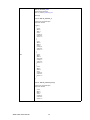
B.2.1 Digital Input
B.2.1.1 /di_value/slot_index/ch_num
Description
Retrieves information about the digital input value resource on specific slot.
URL Structure
http://10.0.0.1/di_value/slot_index
http://10.0.0.1/di_value/slot_index/ch_num
HTTP Method
GET:Returns the representation of all of digital input value resource.
PUT:Replace all of digital input value resource
PATCH:Apply partial modifications to digital input value resource.
73
WISE-4000 User Manual
Appendix B REST for WISE-4000
B.2 REST Resources for WISE-4000
Multiple Channel Request:
GET /di_value/slot_index
Single Channel Request:
GET /di_value/slot_index/ch_num
[Example]
Request: GET /di_value/slot_0
GET
Content-type: application/json
Response: 200 OK
{
"DIVal": [
{
"Ch":0,
"Md":0,
"Stat":1,
"Val":1,
"Cnting":0,
"ClrCnt":0,
"OvLch": 0
},
{
"Ch":1,
"Md":0,
"Stat":0,
"Val":0,
"Cnting":0,
"ClrCnt":0,
"OvLch": 0
},
{
"Ch":2,
"Md":1,
"Stat":0,
"Val":3378,
"Cnting":1,
"ClrCnt":0,
"OvLch": 0
},
{
"Ch":3,
"Md":3,
"Stat":0,
"Val":1,
"Cnting":0,
"ClrCnt":0,
"OvLch": 0
}
]
}
Request : GET /di_value/slot_0/ch_2
Content-type: application/json
Response: 200 OK
{
"Ch":2,
"Md":0,
"Stat":1,
"Val":1,
"Cnting":0,
"ClrCnt":0,
"OvLch": 0
}
WISE-4000 User Manual
74
Appendix B REST for WISE-4000
Single/Multiple Channel Request:
PUT /di_value/slot_index
Single Channel Request:
PUT /di_value/slot_index/ch_num
[Example]
Request: PUT /di_value/slot_0
Content-type: application/json
{
"DIVal": [
{
"Ch":0,
"Md":0,
"Stat":0,
"Val":0,
"Cnting":0,
"ClrCnt":0,
"OvLch": 0
},
{
"Ch":1,
"Md":0,
"Stat":0,
"Val":0,
"Cnting":0,
"ClrCnt":0,
"OvLch": 0
},
{
"Ch":2,
"Md":1,
"Stat":0,
"Val":3378,
"Cnting":0,
"ClrCnt":1,
"OvLch": 0
},
{
"Ch":3,
"Md":3,
"Stat":0,
"Val":0,
"Cnting":0,
"ClrCnt":0,
"OvLch": 0
}
PUT
]
}
Response: 200 OK
Request: PUT /di_value/slot_0/ch_2
Content-type: application/json
{
"Ch":2,
"Md":1,
"Stat":0,
"Val":3378,
"Cnting":0,
"ClrCnt":1,
"OvLch": 0
}
Response: 200 OK
75
WISE-4000 User Manual
Single/Multiple Channel Request:
PATCH /di_value/slot_index
Single Channel Request:
PATCH /di_value/slot_index/ch_num
[Example]
Request: PATCH /di_value/slot_0
PATCH
Content-type: application/json
{
"DIVal": [
{
"Ch":2,
"Cnting": 1
},
{
"Ch":3,
"OvLch":0
}
]
}
Response: 200 OK
Request: PATCH /di_value/slot_0/ch_3
Content-type: application/json
{
"Ch":3,
"ClrCnt":1
}
Response: 200 OK
JSON array name definition:
Field
Abbreviation Data Type
Array of Digital input configurations
DIVal
WISE-4000 User Manual
76
Array
Resource value definitions:
Field
Abbreviation
Data Type
Property
Description
Channel Number
Ch
Number
R
0, 1, …: Digital input channel number.
Digital input mode.
Mode
Signal Logic Status
Md
Stat
Number
Number
R
R
0
DI
1
Counter
2
LowToHighLatch
3
HighToLowLatch
4
Frequency
1, 0: Input signal is Logic High or Low.
DI measurement data
Channel Value
Val
Number
R
Input Mode
Value Description
DI
Logic Status of DI
Counter
Counter Value
LowToHighLatch
Logic status of DI
HighToLowLatch
Logic status of DI
Frequency
Frequency(unity 0.1 Hz
Start Counter
Cnting
Number
RW
Start/Stop counter counting
Read
1 : counter is counting
0 : not counting
Write
1 : start counting
0 : stop counting
Clear Counter
ClrCnt
Number
W
1 : Clear the counter value
RW
counter overflow or latch status
Read
1 : overflow/latch occurred.
0 : no overflow or latch
Write
0 : clear the overflow or latch status
Get/Clear Counter
Overflow or Latch Sta- OvLch
tus
Number
77
WISE-4000 User Manual
Appendix B REST for WISE-4000
B.2.2 Digital Output
B.2.2.1 /do_value/slot_index/ch_num
Description
Retrieves information about the digital output value resource on specific slot.
URL Structure
http://10.0.0.1/do_value/slot_index
http://10.0.0.1/do_value/slot_index/ch_num
HTTP Method
GET:Returns the representation of all of digital output value resource.
PUT:Replace all of digital output value resource
PATCH:Apply partial modifications to digital output value resource.
WISE-4000 User Manual
78
Appendix B REST for WISE-4000
Multiple Channel Request:
GET /do_value/slot_index
Single Channel Request:
GET /do_value/slot_index/ch_num
[Example]
Request: GET /do_value/slot_0
GET
Content-type: application/json
Response: 200 OK
{
"DOVal": [
{
"Ch":0,
"Md":0,
"Stat":1,
"Val":1,
"PsCtn":0,
"PsStop":0,
"PsIV": 0
},
{
"Ch":1,
"Md":0,
"Stat":0,
"Val":0,
"PsCtn":0,
"PsStop":0,
"PsIV": 0
},
{
"Ch":2,
"Md":1,
"Stat":1,
"Val":3378,
"PsCtn":0,
"PsStop":0,
"PsIV": 0
},
{
"Ch":3,
"Md":3,
"Stat":1,
"Val":1,
"PsCtn":0,
"PsStop":0,
"PsIV": 0
}
]
}
Request : GET /do_value/slot_0/ch_2
Content-type: application/json
Response: 200 OK
{
"Ch":2,
"Md":0,
"Stat":1,
"Val":1,
"PsCtn":0,
"PsStop":0,
"PsIV": 0
}
79
WISE-4000 User Manual
Single/Multiple Channel Request:
PUT /do_value/slot_index
Single Channel Request:
PUT /do_value/slot_index/ch_num
[Example]
Request: PUT /do_value/slot_0
PUT
Content-type: application/json
{
"DOVal": [
{
"Ch":0,
"Md":0,
"Stat":1,
"Val":1,
"PsCtn":0,
"PsStop":0,
"PsIV": 0
},
{
"Ch":1,
"Md":0,
"Stat":0,
"Val":0,
"PsCtn":0,
"PsStop":0,
"PsIV": 0
},
{
"Ch":2,
"Md":1,
"Stat":1,
"Val":3378,
"PsCtn":0,
"PsStop":0,
"PsIV": 0
},
{
"Ch":3,
"Md":3,
"Stat":1,
"Val":1,
"PsCtn":0,
"PsStop":0,
"PsIV": 0
}
]
}
Response: 200 OK
Request: PUT /do_value/slot_0/ch_2
Content-type: application/json
{
"Ch":2,
"Md":2,
"Stat":0,
"Val":0,
"PsCtn":0,
"PsStop":0,
"PsIV": 0
}
Response: 200 OK
WISE-4000 User Manual
80
Appendix B REST for WISE-4000
Single/Multiple Channel Request:
PATCH /do_value/slot_index
Single Channel Request:
PATCH /do_value/slot_index/ch_num
[Example]
Request: PATCH /do_value/slot_0
PATCH
Content-type: application/json
{
"DOVal": [
{
"Ch":2,
"Md": 2
},
{
"Ch":3,
"PsStop":1
}
]
}
Response: 200 OK
Request: PATCH /do_value/slot_0/ch_3
Content-type: application/json
{
"Ch":3,
"PsCtn":1
}
Response: 200 OK
JSON array name definition:
Field
Abbreviation Data Type
Array of Digital input
configurations
DOVal
Array
81
WISE-4000 User Manual
Resource value definitions:
Field
Abbreviation Data Type
Property Description
Channel Number
Ch
R
Number
0, 1, …: Digital output channel number.
Digital output mode.
Mode
Signal Logic Status
Md
Stat
Number
Number
R
R
0
DO
1
Pulse Output
2
LowToHighDelay
3
HighToLowDelay
1, 0: Output signal is Logic High or Low.
DO measurement data
Output Mode
Value Description
DO
Get the current signal status or set its status
Channel Value
Val
Number
RW
Pulse Output
Get or set the absolute pulse count value
LowToHighDelay
Get the current signal status or set its status
HighToLowDelay
Get the current signal status or set its status
Pulse Output Continue
PsCtn
State
Number
RW
1 / 0: Pulse outputting is continuous or not.
Stop Pulse Output
Number
W
1: Stop the pulse outputting.
(Continue is disabled, Absolute and incremental
values are reset to zero. DO signal status is set to
logic low.)
Number
RW
Incremental Pulse Output Value
PsStop
Incremental Pulse OutPsIV
put Value
WISE-4000 User Manual
82
B.2.3.1 /ai_value/slot_index/ch_num
Description
Retrieves information about the analog input value resource on specific slot.
URL Structure
http://10.0.0.1/ai_value/slot_index
http://10.0.0.1/ai_value/slot_index/ch_num
HTTP Method
GET:Returns the representation of all of analog input value resource.
PUT:None
PATCH:Apply partial modifications to analog input value resource.
83
WISE-4000 User Manual
Appendix B REST for WISE-4000
B.2.3 Analog Input
Multiple Channel Request:
GET /ai_value/slot_index
Single Channel Request:
GET /ai_value/slot_index/ch_num
[Example]
Request : GET /ai_value/slot_0
GET
WISE-4000 User Manual
Content-type: application/json
Response: 200 OK
{
"AIVal": [
{
"Ch":0,
"En":1,
"Rng":328,
"Val":148,
"Eg":650,
"Evt":0,
"LoA": 0,
"HiA": 0,
"HVal":190,
"HEg":1250,
"LVal":15,
"LEg":500,
"SVal":148,
"ClrH": 0,
"ClrL": 0
},
{
"Ch":1,
"En":1,
"Rng":328,
"Val":0,
"Eg":0,
"Evt":0,
"LoA":0,
"HiA":0,
"HVal":0,
"HEg":0,
"LVal":0,
"LEg":0,
"SVal":0,
"ClrH": 0,
"ClrL": 0
},
{
"Ch":2,
"En":1,
84
Appendix B REST for WISE-4000
"Rng":328,
"Val":0,
"Eg":0,
"Evt":8,
"LoA":0,
"HiA":0,
"HVal":0,
"HEg":0,
"LVal":0,
"LEg":0,
"SVal":0,
"ClrH": 0,
"ClrL": 0
},
{
"Ch":3,
"En":1,
"Rng":328,
"Val":0,
"Eg":0,
"Evt":0,
"LoA":0,
"HiA":0,
"HVal":0,
"HEg":0,
"LVal":0,
"LEg":0,
"SVal":0,
"ClrH": 0,
"ClrL": 0
},
{
"Ch":4,
"En":1,
"Rng":328,
"Val":0,
"Eg":0,
"Evt":0,
"LoA":0,
"HiA":0,
"HVal":0,
"HEg":0,
"LVal":0,
"LEg":0,
"SVal":0,
"ClrH": 0,
"ClrL": 0
}
]
}
Request : GET /ai_value/slot_0/ch_2
Content-type: application/json
Response: 200 OK
{
"Ch":2,
"En":1,
"Rng":328,
"Val":0,
"Eg":0,
"Evt":8,
"LoA":0,
"HiA":0,
"HVal":0,
"HEg":0,
"LVal":0,
"LEg":0,
"SVal":0,
"ClrH": 0,
"ClrL": 0
}
PUT
None
85
WISE-4000 User Manual
Single/Multi Channel Request:
PATCH /ai_value/slot_index
Single Channel Request:
PATCH /ai_value/slot_index/ch_num
[Example]
Request: PATCH /ai_value/slot_0
Content-type: application/json
{
"AIVal": [
{
"Ch":2,
"LoA": 0
},
{
"Ch":3,
"HiA":0
}
]
}
PATCH
Response: 200 OK
Request: PATCH /ai_value/slot_0/ch_3
Content-type: application/json
{
"LoA":0
}
Response: 200 OK
JSON array name definition:
Field
Abbreviation
Data Type
Array of Analog input
configurations
AIVal
Array
WISE-4000 User Manual
86
Resource value definitions (Total channels = AI channel number + 1 average
channel):
Field
Channel Number
Abbreviation
Ch
Data Type
Number
Property Description
R
0, 1, …: Analog input channel
number.
Note for the average channel:
The average channel number for a 4-ch AI
module is 4.
Analog input range.
Range code
Input Range
Rng
Number
R
328
(0x0148) 0 – 10 V
259
(0x0103) +/- 150 mV
260
(0x0104) +/- 500 mV
320
(0x0140) +/- 1 V
321
(0x0141) +/- 2.5 V
322
(0x0142) +/- 5 V
323
(0x0143) +/- 10 V
327
(0x0147) 0 ~ 5 V
384
(0x0180) 4 ~ 20 mA
385
(0x0181) +/- 20 mA
386
(0x0182) 0 ~ 20 mA
65535
Invalid range, if ave
channel is disable
Channel Enable
En
Number
R
1 / 0: Enable / Disable AI conversion
Notice: Average channel is read only. When
channel mask of average is not 0, the value
is 1.
Channel Raw
Value
Val
Number
R
0 ~ 65535 :AI measurement data (Raw data)
Channel Engineering data
Eg
Number
R
AI engineering data, the value is 1/1000
scale.
For example,
1630 1.63
Channel Event
Status
Evt
Number
R
AI statuses
RW
Low alarm status
Read
1 : low alarm occurred.
0 : not occurred
Write
0 : clear the low alarm status
Low Alarm Status LoA
Number
High Alarm Status HiA
Number
RW
High alarm status
Read
1 : high alarm occurred.
0 : not occurred
Write
0 : clear the high alarm status
Maximum AI
Raw Value
Number
R
AI max. measurement data (Raw data)
HVal
87
WISE-4000 User Manual
Appendix B REST for WISE-4000
Maximum AI
Engineering data
HEg
Number
R
AI max. engineering data, the value is 1/1000
scale
For example,
1020010.2
Minimum AI
Raw Value
LVal
Number
R
AI min. measurement data (Raw data)
Minimum AI
Engineering data
LEg
Number
R
AI min. engineering data, the value is 1/1000
scale
For example,
250 0.25
Channel Raw
Value After Scaling
SVal
Number
R
0 ~ 65535 : AI measurement data (Raw data)
after scaling
Clear Maximum
AI Value
ClrH
Number
W
1 : Clear the Maximum AI value
Clear Minimum
AI Value
ClrL
Number
W
1 : Clear the Minimum AI value
* AI Status (2 Registers)
Lower Register
Bit
Higher Register
Description
Bit
Description
0
Fail to Provide AI Value
0
DI triggered to Safety Value
1
Over Range
1
DI triggered to Startup Value
2
Under Range
2
Reserved
3
Open Circuit / Burnout
3
Reserved
4
Reserved
4
Reserved
5
Reserved
5
Reserved
6
Reserved
6
Reserved
7
ADC Initializing/Error
7
Reserved
8
Reserved
8
Reserved
9
Zero/Span Calibration Error
9
Reserved
10
Reserved
10
Reserved
11
Reserved
11
Reserved
12
Reserved
12
Reserved
13
Reserved
13
Reserved
14
Reserved
14
Reserved
15
Reserved
15
Reserved
WISE-4000 User Manual
88
Appendix B REST for WISE-4000
WISE-4000 User Manual
89
www.advantech.com
Please verify specifications before quoting. This guide is intended for reference
purposes only.
All product specifications are subject to change without notice.
No part of this publication may be reproduced in any form or by any means,
electronic, photocopying, recording or otherwise, without prior written permission of the publisher.
All brand and product names are trademarks or registered trademarks of their
respective companies.
© Advantech Co., Ltd. 2015