1
w w w. i c m . c o m . t w
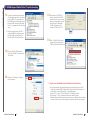
1 OBD TRACE
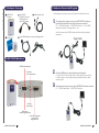
3 USB Hi-Speed Cable
2 16-pin OBDII
Diagnostic Connector
*Please find it from
WIN-STAR Package.
Hardware
w w w. i c m . c o m . t w
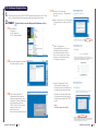
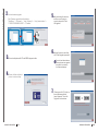
3. Hardware Connection Diagram
1.Hardware Coverage
Before diagnosis, please connect your Diagnostic Interface as below.
1.
To configure data, please connect your OBD TRACE interface as
below:The red light will be on when interface is connected.
PC → USB Hi Speed cable → OBD TRACE interface → 16-pin OBDII
diagnostic connector and trigger cable → car
Note: Must remove the USB Hi Speed cable after configuring data is
completed.
4 Software CD
5 16-pin OBDII diagnostic connector and trigger cable
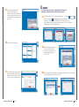
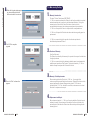
2.OBD TRACE Hardware
USB Hi Speed cable port
Green light:
communication light
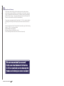
2.
3.
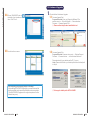
Check the OBD trace is connected when recording data
a. Turn the IG ON .The red light will be on when interface is connected.
b. Start the engine. The red light and green light will be both on when
recording data.
To Analyze data, please connect your OBD TRACE interface as below:
PC → USB Hi Speed cable → OBD TRACE interface
Red light:
wake up light
Black button:
firmware upgrade button
16-pin OBDII diagnostic
connector and
trigger cable Port
DIAGNOSIS REVOLUTION
1
DIAGNOSIS REVOLUTION
2