1
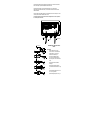
2.
Not responding to applied pressure. Dissconnect the Red and Black sensor wires
Is it now possible to set 4mA output on the zero pot?
If YES, it indicates a sensor problem or no exitation voltage being supplied by the
amplifier module. To check the exitation voltage connect an AC voltmeter across the
Ex+ & Ex- terminals. Output should read 0.7V @ 1.3KHz. If an oscilloscope is available
the frequency can also be verified.
If NO, there is a problem with the amplifier module. To check the supply rails the
amplifier must be removed from its housing to gain access to the lower board. Check that
the voltage across Diode Z1 is 5.2V. Z1 is located in the centre of the board and its
unbanded end is 0V. Measure also from this 0V to pin 13 of IC4. This should be 1.9V.
Any variation from these two values indicates a problem with the amplifier module.
Where the foregoing do not clearly indicate the faulty element, careful visual inspection of the
sensor body/diaphragm should be made for signs of damage/corrosion, the sensor cable for signs of
damage to the outer sheathing, and the circuit board for component failure or breakage, may
indicate where the problem lies. If this is the case and a spare sensor or amplifier module is
available, the following matching procedure should be undertaken.
10.0 SENSOR/AMPLIFIER MODULE REPLACEMENT
1.
To access the potentiometers on the lower PCB of the RT168 amplifier module it is
necessary to remove the assembly from its enclosure. Take care not to damage the
boards or interconnecting ribbon cable.
2.
Connect sensor to transmitter and apply power as previously described.
3.
Set the potentiometer controls as follows:RV1 - Phase control - fully anti-clockwise. (Lower PCB)
RV2 - Zero control - mid-position. (Upper PCB)
RV3 - Gain control - fully anti-clockwise. (Lower PCB)
RV4 - Range control - fully anti-clockwise. (Upper PCB)
4.
With no pressure applied adjust the zero control RV2 to give an output signal of 4.00mA.
5.
Apply the full nominal pressure of the instrument and adjust RV3 gain control to give an
output signal of 18.4mA.
6.
Release the pressure and recheck zero output adjusting RV2 if necessary to give 4.00mA.
7.
Re-apply the full nominal pressure and check output signal adjusting to 18.4mA using
RV3 as necessary.
8.
Now apply the actual calibration pressure for full scale and adjust RV4 to give 20.00mA
output.
9.
Release the pressure and recheck zero output. If it requires correction check span
afterwards. Repeat this process until a 4-20mA output is achieved.
16


![ユーザーズマニュアル [PDF形式]](http://vs1.manualzilla.com/store/data/006585855_3-9740afd391b22c0ca202682cfffb3858-150x150.png)