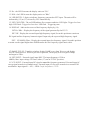
1
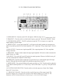
USER'S MANUAL
5MHz
FUNCTION GENERATOR
FG-52
FG-53 is using FG-52 USER MANUAL
1.
FG-53 operation is similar to FG-52. Thus, FG-53 uses FG-52
manual temperately.
2.
The only difference of FG-53 is changing FG-52 DC OFFSET
OUTPUT to very useful voltage amplify function.
3.
When FG-53 is using as a voltage amplifier, the input signal less
than +/-5Vp-p (≦+/- 5Vp-p), Max output is able to +/-20Vp-p.
Bandwidth: DC ~ 5MHz, Max Current: 40mA.
4.
FG-53 is able to use AMPLE knob to adjust Gain to 10 times. It
also can use DC offset knob to adjust DC bias voltage. FG-53 is
a very useful model for amplifying small signals experiments.
I. NOTICE BEFORE OPERATION
1. Unpack the instrument :
After receipt of the instrument, immediately unpack and inspect it for any damage which might have been
sustained when in transportation or shortage of accessories. If any sign of damage and shortage of accessories
are found, immediately notify the dealer.
2. Environments :
Normally, operational temperature of the instrument is 10ºC to 40ºC (50ºF to 104ºF ) . Operation of the
instrument outside of this temperature range may cause damage to the circuits. Do not use the instrument in a
place where strong magnetic or electrical field exists. Such fields may disturb the measurement.
3. Check the Line Voltage :
The instrument can operate on any one of the line voltages shown in the below table by
inserting the line voltage selector plug in the corresponding position on the rear panel.
Before connection the power plug to an AC line outlet, be sure to check that voltage
selector plug is set in the correct position corresponding to the line voltage.
CAUTION : The instrument may not properly operate or may be damage if it is connected to
a wrong voltage AC line. When line voltages are changed, replace fuses also a required.
SELECTOR
115V
230V
LINE VOLTAGE
100 ~ 125V 50/60Hz
220 ~ 240V 50/60Hz
FUSE
600mA
300mA
Hints for operation the instrument observe the following suggestions for
successful instrument operation.
1. Never place heavy objects on the instrument.
2. Never place a hot soldering iron on or near the instrument.
3. Never insert wires, pins or other metal objects into ventilation fan.
4. Never move or pull the instrument with power cord or probe cord.
Especially never move instrument when power cord or signal probe is
connected to a circuit.
5. If the instrument is used in a manner not specified by the manufacturer,
the protection provided by the equipment may be impaired.
WARNING : The following precautions must be observed to help prevent electric shock.
1. When the instrument is used to make testing. There is always a certain
amount of danger from electrical shock. The person using the instrument in
such condition should be a qualified electronics technician or otherwise trained
and qualified to work in such circumstance.
2. Do not operate the instrument with the cover removed unless you are a
qualified service technician.
3. The ground wire of the 3-wire Ac power plug places the chassis and
housing of the instrument at earth ground. Use only a 3-wire outlet, and do
not attempt to defeat the ground wire connection or float the instrument. to
do so may pose a great safety hazard.
4. Do not obstruct the ventilation holes in the rear panel. As this will
increase the internal temperature.
5. Never apply external voltage to output BNC of the instrument.
6. Excessive voltage applied to the input BNC may damage the instrument.
II. FG-52 GENERAL
DESCRIPTION :
The FG-52 is a super deluxe function Generator combined a 5 digits, high resolution 60MHz counter.
The FG-52 is a rugged, easy to operate, excellent heat dissipation and high stability instrument.
The FG-52 is 4 in 1 instrument. It can be used as the following describes 4 kinds of electronic instrument
respectively.
1. To be as Function Generator :
8 wave forms selected by rotary switch instead of push-button to prevent mis-touch or bad
connection. Max. output 20Vp-p (Non-load),and Mini. output 0.1Vp-p (Non load).
2. To be as Pulse Generator :
FG-52 provide positive pulse and reverse negative pulse output by Pull Reverse Switch, Max. output 20Vp-p
(Non-load).
Frequency display by LED, pulse width from 0.4sec to 100ns.Can meet most of Audio, Video and other
Basic electronic application requirement.
3. To be as Sweep Generator :
FG-52 provide linear sweep or log sweep selection switch to select the sweep mood. Max. sweep width
1:100 and sweep speed 5sec to 10ms. Also FG-52 provide VCF input and synchronous Output Function.
Convenient to operate.
4. To be as counter :
FG-52 is a 5 digits micro-control counter. FG-52 provide Auto range, Auto gate time and high resolution
- 0.001Hz, High input impedance -1MΩ, High band width - 0.2Hz ∼ 60Mhz, High voltage resistance
-150Vp-p features, Also, FG-32 provide Adjustable Trigger +/- 2.5V with LED indicate.
Display unit Auto - indicate, HF / LF selector, 100Khz filter.
5. To be as Dry Battery :
FG-52 provide a DC Output function. The output voltage from +10V to -10 continuous adjustable.
Can be used as a low power DC source. Dry Battery.
III. FG-52 SPECIFICATIONS
1. General Specifications :
Generator Frequency : 0.05Hz ∼ 5MHz display by 5 digits LED, Max. resolution 0.001Hz in 8 ranges.
Wave form output : Sine, Square, Triangle, Positive , Ramp, Negative Ramp, Positive Pulse and
Negative Pulse, DC 8 wave forms.
Stability : 0.1% ∼15 minutes after switch "ON", 0.2% ∼ 24hrs after switch "ON".
DC offset : +/- 10V(No. Load ), +/- 5V(50Ω Load), continuous adjustable, controlled by a offset
switch.
Counter Display : 5 digits 0.36" red LED. Max. Resolution - 0.001HZ.
Display unit : Hz / KHz Automatically controlled by CPU.
Common Specification Limits of operation : 0℃ ∼ 40℃, 10% ∼ 80% R.H.
Storage environment : -20℃ ∼ 70℃, 0% ∼ 90% R.H.
Power consumption : 25W.
Power source :
AC 115V (+/- 10%) 50/60Hz, FUSE : 600mA
AC 230V (+/- 10%) 50/60Hz, FUSE : 300mA
Ventilation : DC 12V / 100mA Fan.
Dimensions : 275 x 90 x 300mm
Weight : 2.5Kgs Net.
Accessories : Power cord, operation manual.
2. Triangle wave :
Frequency : 0.05Hz ∼ 5MHz, 5 digits LED display, Max. resolution 0.001Hz
Symmetry : 50% (Rise wave) to 50% (Fall wave), < 1%, 1Hz ∼100KHz
Linearity : < 1%, (1Hz ∼100KHz).
3. Sine Wave :
Frequency : 0.05Hz ∼ 5MHz, 5 digits LED display, Max. resolution 0.001Hz.
Distortion : < 1%, 1Hz ∼100KHz.
Harmonic ratio : < 30dB, 100KHz ∼ 5MHz
Frequency response : < 0.1dB, up to 100KHz., < 1.5dB, 100KHz to 5MHz.
4. Square wave :
Frequency : 0.05Hz ∼ 5MHz, 5 digits LED display, Max. resolution 0.001Hz.
Symmetry : 50% (Positive half) to 50% (Negative half). < 1%, 1Hz ∼100KHz
Rise time : < 90ns (20Vp-p , No load).
5. Ramp wave :
Frequency : 0.05Hz ∼ 4.5MHz, 5 digits LED display, Max. resolution 0.001Hz,
8 range selected by rotary switch.
Symmetry : 90% (Rise wave) to 10% (Fall wave), continuous adjustable.
Linearity : < 1%, (0.1Hz ∼100KHz).
6. Positive pulse :
Frequency : 0.05Hz ∼4.5MHz, 5 digits LED display, Max. resolution 0.001 Hz.
Width : 0.4sec ∼100ns, continuous adjustable.
Symmetry - 1:1 to 10:1 continuous adjustable. 1Hz ∼100KHz.
Reverse : Pull the Rev, switch, the output will becomes Negative Pulse.
7. DC :
Output voltage : +10V to -10V continuous adjustable by OFFSET switch.
8. Main output :
Output impedance : 50Ω, < 2%
Max. Output : 20Vp-p (Non-load), +/- 1Vp-p., 10Vp-p (50Ω load) +/- 0.5V.
Min. Output : 0.1Vp-p (Non-load), or 0.05Vp-p (50Ω load)
Attenuator : One -26dB (1/20) Attenuator, < 2% Accuracy
9. Synchronous Output :
Output impedance : 50Ω, < 2%, Accuracy.
Output level : TTL level, > 3Vp-p fix amplitude.
Fan out : > 20
Rise time : <60nS.
10. VCF input :
Input impedance : 0 ∼10V
Input frequency : DC ∼1KHz
Input frequency variety - 1:1 to 1:100
11. Sweep synchronous output :
Output impedance : 1KΩ, < 2%
Output wave form : Linear or log sweep ramp wave.
Output amplitude : 10Vp-p (Non load) or 5Vp-p (1KΩ load)
Output frequency : 0.2Hz ∼100Hz continuous adjustable.
12. Sweep generator :
Sweep form : Linear or log switchable.
Sweep speed : 5sec ∼10ms, continuous adjustable.
Sweep width - 1:1 ∼1:100
13. Counter :
Display : 5 digits, 0.36" RED LED display.
Max. Resolution : 0.001Hz
Display unit : Hz / KHz Auto range.
Time base : 20MHz
Temperature coefficient : < 20ppm/ ºC
Accuracy : < 0.02% +/- 1 digit.
Power supply : +5V, 160mA
Internal counter Range :
Auto range with 4 resolution,
0.001Hz / 0.01Hz / 0.001KHz / 0.01KHz, Auto control by CPU.
Display : 0.500Hz ∼ 5000.0KHz A u t o select by CPU.
Gate time : Variable, 0.25sec ∼5sec, Auto - setting.
Min. Display digits : 4 digits.
External counter Max. Input voltage : < 150Vrms
Input impedance : 1MΩ, < 2%
Input frequency : 0.2Hz ∼60MHz
Coupling :
HF - For 100KHz up frequency.
LF -- With 100KHz filter, for the frequency lower than 100KHz
Min. display digits : 4 digits.
Gate time : 0.25sec ∼10sec, Auto - setting depends on the input frequency
Sensitivity : > 30mVrms (1MHz)
IV. FG-52 FRONT PANEL DESCRIPTION
---------
--------3
6
------
---------
--------4
7
8
------
--------18 19
9
------
17
------
16
10
------
---------
-------
2
------------------------
1
-------
------
15 --------
13 12 11
------
---------
14
5
1. POWER SWITCH - Push the switch "ON" will light the LED of the digits (14) to indicate power "ON".
2. FREQUENCY - Turn the switch to set the desired frequency generated. This knob is for micro – adjust.
3. SYNCHRONOUS OUTPUT - The BNC synchronous output the TTL level square wave signal, the
output frequency as MAIN output.
4. SWEEP OUTPUT - Sweep signal output BNC. It will operate individually whether the instrument was
under sweep mode operation or not, Out put impedance 1kΩ, output amp. 10Vp-p, output signal : Linear or
Log.
5. MAIN OUTPUT - Function wave signal output BNC, Max. output impedance 50Ω Max. amplitude
20Vp-p (Non load).
6. AMPLITUDE - Turn the switch to adjust the output signal amplitude. Pull out the switch to attenuate the
output 20 times (or -26dB).
7. DC OFFSET - The switch will set at OFF position in normal operation. When use for BIAS circuit, pull
"ON" the switch and turn to adjust DC offset voltage.
8. SWEEP RATE - Turn the switch to adjust the sweep rate from 5sec to 10mS and the signal will output
from (4). When pull the switch, the signal will synchronous output from (4) and (5).
9. SWEEP WIDTH - The switch will effected only under switch (8) was "ON". Turn the switch to adjust the
sweep width. In normal position. It is " Linear sweep " and it will be under " Log sweep " when pull out the
switch.
10. FUNCTION WAVE SELECTOR - Turn the switch to select the output wave forms. Sine, Triangle,
Square, DC, 4wave forms.
11. FREQUENCY RANGE - Turn the switch to set the frequency of the output signal. The
frequency display on (14) will beas the product of the indicated digits by (2) and (11). The
frequency will be 10 times difference on each step.x1, x10, x100, x1000 4ranges.
12. Hz - the LED lit means the display units are "Hz".
13. KHz - the LED lit meas the display units are "Khz".
14. LED DIGITS - 5 digits to indicate frequency generated or EXT input. The units will be
indicated by (12) or (13) selected by CPU automatically.
15. EXT-COUNTER - The red LED indicate Ext. counter condition. LED Light - Trigger level too
high. LED Dark - Trigger level too low. LED flash - Triggering state.
16. DISPLAY - Indicate the source of the frequency display by (14).
INT Hz / KHz -- Display the frequency of the signal generated by the FG-52.
EXT HF - Display the external input high frequency signal, Set at this position to strain out
DC signal and low frequency harmonic signal. Input only the expected high frequency signal.
EXT - LF 100KHz Filter - Display the external input low frequency signal, Set at this position
to strain out the signal higher than 100KHz make the low frequency signal more stable.
17. RAMP / PULSE - Turn this switch to display RAMP wave from Tri wave and display
PULSE from squ wave. When at pull Invert position, The display will be negative Ramp
and negative Pulse.
18. EXT-INPUT - External signal input BNC. The input frequency 0.2Hz to
60MHz, Max. input voltage 150Vrms (when (17) was at "PULL" position).
19. VCF-INPUT - External input DC signal to control the frequency generated. External input AC
sweep signal to make it as External sweep. External input AC sine wave to make it as external FM
modulation. Input signal 0 ∼10V, < 1KHz. Input impedance 1KΩ.
V. FG-52 OPERATION INSTRUCTIONS
WARNING : Before applying power to your FG-52, make sure that the input voltage
setting is correct for your power source.
CAUTION : All the knobs are set at " PUSH " position on operation if not special
marked to be set at " PULL ".
(A). Function Generator and Inspection ( Ref. to Fig.9-1)
7
------
5
------
-------
4
------ 6
1
------
-----
-------- 2
3
1. Push the power switch on and make sure that the LED of the 5 digits are lit.
2. Connect OUTPUT BNC of FG-52 to the CH1 input BNC of your Oscilloscope, and the SYNC
OUTPUT BNC to CH2, and set the trigger source of your oscilloscope at CH2.
3. Turn the FREQUENCY knob from x0.05 ∼ x5.0 You will find the display of 5 digits LED and
oscilloscope will be changed slightly on each step.
4. Turn the RANGE knob from x1 ∼ x1000. You will find the display of 5 digits LED value will change 10
time on each step and the oscilloscope too. And then see (7) switch at Hz or KHz the display value will be
changed to x1 or x1000 too.
5. Turn the FUNCTION knob to select the wave form output to CH1 of your
Oscilloscope. CH2 will be TTL square wave only.
6. Turn the AMPL knob to adjust the amplitude of the signal output to CH1, and
when " PULL " out the switch, the amplitude will be reduced 20 times ( -20dB)
but the display of CH2 (Sync output signal) will keep unchanged.
7. Turn the OFFSET knob. You will find both CH1 and CH2 will not changed.
This switch will operated only at " PULL " position. PULL out the offset switch and turn to
set DC offset voltage (from +10V to -10V) of the main output signal. But the sync output
signal will not affected.
Note : When the offset voltage are higher then the wave (+ or -) the display wave form will
be cut OFF.
(B). SWEEP GENERATOR (Ref. to Fig 9-2)
3
4
-------
6
------
8
------
1
------
------
--------
--------
5
--------
7
2
1. Switch on the FG-52 and lit the 5 digits LED.
2. Connect the main OUTPUT BNC to the CH1 input BNC of you Oscilloscope.
3. Connect the SWEEP OUTPUT BNC to the CH2 input BNC of your Oscilloscope
and set the trigger source of the oscilloscope at CH2.
4. Turn the SWEEP RATE knob, the CH2 of the oscilloscope will display a
linear saw - tooth wave, the frequency will be variable from 5sec to 10mS
by turn the switch. CH1 will display the wave according to the
FUNCTION switch position. PULL out the switch to set "SWEEP ON". the
display of CH2 will keep unchanged, the display frequency will be variant by
turn the knobs. But the display of CH1 will be sweep wave, and the sweep speed
will depend on the sweep rate.
NOTE : After "PULL SWEEP ON", the trigger source of the oscilloscope must
be changed from CH2 to CH1.
5. Turn the SWEEP WIDTH knob to adjust the sweep width by the display of CH1.
NOTE:Be sure that the SWEEP RATE SWITCH was at " PULL " position.
When PULL out the sweep width switch, the sweep mode will changed
from linear to log sweep. The wave form display of CH1 will becomes
log form.
6. AMPL and FUNCTION knobs will operate as Generator.
7. Frequency display on 5 digits LED as Generator, before "PULL SWEEP ON".
this frequency will be the start frequency. After "PULL SWEEP ON", the sweep
condition include frequency, wave form and sweep mode etc. will be observed
from the CRT of the Oscilloscope. The display on LED will continuous variety.
8. VCF INPUT - Set the sweep rate switch at "PUSH" position to set FG-52 at
normal generator mode. connect the sweep output BNC to VCF INPUT BNC and
check the wave form display on the scope CH1. the wave form display would be
the sweep wave. When input a sine wave from an other generator to VCF INPUT
to observe the FM display. Be sure the frequency of the basic wave (FG-52) are
higher than the external input signal.
(C). PULSE wave Generator (Ref. to Fig.9-3)
8
3
--------
--------
--------
9
------
6
7
4
------
5
------
1
------
------
--------
5
2
1.
2.
3.
4.
Push the power on and lit the 5 digits LED.
Connect the main output to CH1.
Connect the SYNC output to CH2 and set the trigger source of the Oscilloscope on CH2.
Set the FUNCTION knob on Squwave position, and turn knob till the display become
pulse wave form you want.
5. Set the FREQUENCY and RANGE to the desired frequency display on LED.
6. Pulse width : the pulse width can be adjustable by knob.
7. Pull knob to display negative pulse position and test the negative pulse as positive pulse.
8. Turn the AMPL to adjust the amplitude of the signal output from the main output BNC.
The signal will be -26dB when " PULL " out the switch. But the signal output
from " SYNC " output BNC will not affect by this switch. The output signal of
" SYNC " output will keep on TTL level.
9. Set the DC offset voltage by pull out the " OFFSET " switch and turn
to adjust the DC offset voltage from +10V to -10V.
(D) Frequency counter (Ref. to Fig. 9-4)
1
2
------
------
-------
----------
4
3
1. Switch on the power switch, lit the LED digits.
2. DISPLAY : The coupling provide 4 steps.
(a). INT/Hz : to be used as internal counter from 0.05Hz~5000Hz.
(b). INT/KHz : to be used as internal counter from 0.5KHz to 5MHz.
(c). EXT HF : To use as External Counter for high frequency (100KHz to 60MHz).
(d). EXT LF : To use a External counter for low frequency (0.2Hz ∼100KHz).
3. Connect the EXT INPUT BNC to the external signal source, lit the LED
4. Display unit : The display unite of the FG-52 will be on Hz or KHz
automatically controlled by CPU.