1
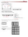
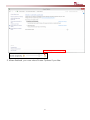
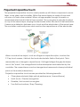
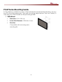
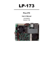
15” P-CAP Chassis P-CAP multi-touch PPC Series User Manual Version 1.0 1 Copyright Notice No part of this document may be reproduced, copied, translated, or transmitted in any form or by any means, electronic or mechanical, for any purpose, without the prior written permission of the original manufacturer. Trademark Acknowledgement Brand and product names are trademarks or registered trademarks of their respective owners. Disclaimer We reserves the right to make changes, without notice, to any product, including circuits and/or software described or contained in this manual in order to improve design and/or performance. We assume no responsibility or liability for the use of the described product(s), conveys no license or title under any patent, copyright, or masks work rights to these products, and makes no representations or warranties that these products are free from patent, copyright, or mask work right infringement, unless otherwise specified. Applications that are described in this manual are for illustration purposes only. We make no representation or warranty that such application will be suitable for the specified use without further testing or modification. Warranty Our warranty that each of its products will be free from material and workmanship defects for a period of one year from the invoice date. If the customer discovers a defect, we will, at its option, repair or replace the defective product at no charge to the customer, provided it is returned during the warranty period of one year, with transportation charges prepaid. The returned product must be properly packaged in it’s original packaging to obtain warranty service. If the serial number and the product shipping data differ by over 30 days, the in-warranty service will be made according to the shipping date. In the serial numbers the third and fourth two digits give the year of manufacture, and the fifth digit means the month (e. g., with A for October, B for November and C for December). For example, the serial number 1W08Axxxxxxxx means October of year 2008. Customer Service We provide service guide for any problem as follow steps: First, visit the website of our distributor to find the update information about the product. Second, contact with your distributor, sales representative, or our customer service center for technical support if you need additional assistance. You may have the following information ready before you call: • Product serial number • Peripheral attachments 2 • Software (OS, version, application software, etc.) • Description of complete problem • The exact wording of any error messages In addition, free technical support is available from our engineers every business day. We are always ready to give advice on application requirements or specific information on the installation and operation of any of our products. Please do not hesitate to call or e-mail us. Safety Information WARNING! Always completely disconnect the power cord from your chassis whenever you work with the hardware. Do not make connections while the power is on. Sensitive electronic components can be damaged by sudden power surges. Only experienced electronics personnel should open the PC chassis. Caution! Always ground yourself to remove any static charge before touching the CPU card. Modern electronic devices are very sensitive to static electric charges. As a safety precaution, use a grounding wrist strap at all times. Place all electronic components in a static-dissipative surface or static-shielded bag when they are not in the chassis. Safety Precautions • Please read these safety instructions carefully. • Please keep this user’s manual for later reference. • Please disconnect this equipment from any AC outlet before cleaning. Do not use liquid or spray detergents for cleaning. Use a damp cloth. • Do not touch the LCD panel surface with sharp or hard objects. • For pluggable equipment, the power outlet must be installed near the equipment and must be easily accessible. • Keep this equipment away from humidity. • Place this equipment on a reliable surface during installation. Dropping it or letting it fall could cause damage. • The openings on the enclosure are for air convection. Protect the equipment from overheating. DO NOT COVER THE OPENINGS. • Make sure the voltage of the power source is correct before connecting the equipment to the power outlet. 3 • Position the power cord so that people cannot step on it. Do not place anything over the power cord. • All cautions and warnings on the equipment should be noted. • If the equipment is not used for a long time, disconnect it from the power source to avoid damage by transient over-voltage. • Never pour any liquid into an opening. This could cause fire or electrical shock. • Never open the equipment. For safety reasons, only qualified service personnel should open the equipment. • If any of the following situations arises, get the equipment checked by service personnel: The power cord or plug is damaged. Liquid has penetrated into the equipment. The equipment has been exposed to moisture. The equipment does not work well, or you cannot get it to work according to the user’s manual. The equipment has been dropped and damaged. The equipment has obvious signs of breakage. • Do not leave this equipment in an uncontrolled environment where the storage temperature is below -20°C (-4°F) or above 40°C (104°F). It may damage the equipment. • Caution – Use recommended mounting apparatus to avoid risk of injury. • WARNING – Only use the connection cords which comes along with the product, when in doubt, please contact the manufacturer. • Provision shall be made to provide transient protection device to be set at a level not exceeding 140% of the rated voltage at the power supply terminals of the apparatus. • WARNING – Explosion Hazard – Do not disconnect equipment unless power has been switched off or the area is known to be non-hazardous. • WARNING – The equipment should be adequately protected from direct light when installed indoor or outdoor. • WARNING – DO NOT OPEN, MAINTAIN OR SERVICE IN AN AREA WHERE AN EXPLOSIVE ATMOSPHERE MAY BE PRESENT. 4 CONTENTS INTRODUCTION.........................................................................6 Features ................................................................................................... 6 Package Contents ................................................................................. 6 Product Overview ......................................................................................6 Input / Output Instruction..........................................................................7 GETTING STARTED .....................................................................8 Turning On Your Device ............................................................................8 Adjusting the LCD Display Brightness ................................................... 8 Projected Capacitive Touch .............................................................. 10 INSTALLATION .........................................................................11 Wiring Requirements ............................................................................ 11 Replacing the Hard Disk on the Hard Drive Bay .............................. 12 PCAP Series Mounting Guide.............................................................. 13 SPECIFICATIONS .....................................................................14 Hardware Specifications ..................................................................... 14 RESTORING OPERATING SYSTEM…………………………..……15 5 INTRODUCTION Winmate extends the line by offering a 15” Multi-touch panel product that combines modern design, very low power consumption processor, removable 2.5” SATA Drive Bay and projected capacitive touch. Features •15” 1024 x 768 Resolution with P-Cap Multi-touch Screen •Low-Power System with Intel® Celeron® N2930 Processor •Fanless Cooling System and Ultra-low Power Consumption •Removable 2.5” SATA Drive Bay •Front IP66 Water and Dust Proof Package Contents Before using this Panel PC, please make sure that all the items listed below are present in your package: Product Overview Front and Side View 6 Rear and Bottom View Input / Output Instruction The input / output instruction are as follows: The pin assignments of the power and COM are as follows: Power terminal block COM RS232/422/485 Pin Signal Name 1 VCC 2 GND 3 NC Pin Signal Name 1 DCD 2 RxD 3 TxD 4 DTR 5 Ground 6 DSR 7 RTX 8 CTS 9 7 RI GETTING STARTED Turning On Your Device 1. Connect the AC adapter to the power cord. 2. Plug the power cord to an electrical outlet. 3. Press the Power button right above the device to turn on it. Adjusting the LCD Display Brightness 1. Open the All Control Panel Items, and click/tap on the Power Options. 2. At the bottom of Power Options, move the Screen brightness slider right (brighter) and left (dimmer) to adjust the screen brightness to what level you like. See the screenshot below. 8 3. When finished, you can close Power Options if you like. 9 Projected Capacitive Touch The projected capacitive touch is mainly made up with three components: sensor layer, cover glass, and controller. Within the sensor layer is a matrix of rows and columns of conductive material. When voltage applies through this matrix, a measurable electrostatic field is then created. The cover glass is optically bonded on top of the sensor layer, burying the electrodes within the stack of the lamination. It serves as a dielectric between your touch and the electrodes of the sensor layer. The controller continually scans and monitors the capacitance of the electrodes. When a conductive object, such as a finger or capacitive stylus, touches the P-Cap touch screen, it distorts the local electrostatic field at that point. This is measurable as a change in capacitance. If a finger bridges the gap between two of the "tracks", the charge field is further interrupted and detected by the controller. The capacitance can be changed and measured at every individual point on the matrix (intersection). Projective capacitive touch screen provides the following benefits: Clear glass substrate (high optical performance / transmittance) Multi-touch / Gesture recognition Durable / Anti-scratch cover glass True flat front surface / Easy Cleaning 10 INSTALLATION Wiring Requirements The following common safety precautions should be observed before installing any electronic device: • Strive to use separate, non-intersecting paths to route power and networking wires. If power wiring and device wiring paths must cross make sure the wires are perpendicular at the intersection point. • Keep the wires separated according to interface. The rule of thumb is that wiring that shares similar electrical characteristics may be bundled together. • Do not bundle input wiring with output wiring. Keep them separate. When necessary, it is strongly advised that you label wiring to all devices in the system. ATTENTION • Do not run signal or communication wiring and power wiring in the same conduit. To avoid interference, wires with different signal characteristics (i.e., different interfaces) should be routed separately. • Be sure to disconnect the power cord before installing and/or wiring your device. • Verify the maximum possible current for each wire gauge, especially for the power cords. Observe all electrical codes dictating the maximum current allowable for each wire gauge. • If the current goes above the maximum ratings (50 W), the wiring could overheat, causing serious damage to your equipment. Be careful when handling the unit. When the unit is plugged in, the internal components generate a lot of heat which may leave the outer casing too hot to touch. 11 Replacing the Hard Disk on the Hard Drive Bay This device has a 2.5” HDD 500GB in default. No tools required to upgrade it or replacing the hard disk, do the following to perform this task: 1. Disconnect the device from the power source. 2. Loosen the thumb screw beside the valve of Hard Drive Bay. 3. Open the valve and take out the bracket with hard disk. 4. Replace the hard disk as you wish, be sure to check the orientation of the hard disk correctly. 5. Insert the bracket back and carefully tighten the thumb screw. 12 PCAP Series Mounting Guide P-Cap Series is suitable for most of the industrial/commercial application, by any kind of mounting approach. The main mounting approaches, such as Chassis, is very easy for user to install as the pictures guided. 1. VESA Mount Dimension: 100 x 100 mm Screw Hole Diameter: VESA M6 x 5 mm Direction: Compatible with swimming arms mounting kits. 13 SPECIFICATIONS Item Specifications System Processor Intel® Celeron® Bay Trail-M N2930 1.83GHz System Chipset Intel® ATOM SoC Integra System Memory 4GB DDR3L-1600 SODIMM, Max 8GB Storage 500GB 2.5” SATA III HDD (Removable) Second Storage 32/64/128GB mSATA SSD (Optional) OS Windows 7 & Windows 8 - Standard/ Professional Input/Output Serial Ports USB Ports 1 x RS232,1 x RS232/422/485* 1 x USB 3.0, 1 x USB 2.0 Ethernet 2 x RJ 45-10/100/1000 Mbps HDMI 1 x HDMI out *Default RS232 Display Specifications Size/Type 15.0" TFT Resolutions 1024x768 Brightness 250cd/m2 (typ.) Contrast Ratio 700 : 1 (typ.) Viewing Angle -80~80(H);-70~70(V) Max Colors 16.2M/262K Projective-Capacitive Touch (up to 4 points) Touch Power Specifications Power Input 12V DC IN Mechanical Specification : Cooling System Fanless Design Mounting VESA Mount(100x100mm) Dimension (W x H x D) 363.40 x 277.86 x 44.50 (mm) Environment Considerations : Operating Temperature -10deg.C to 50deg.C 14 RESTORING OPERATING SYSTEM Using Recovery Wizard to Restore Panel PC Our system has a dedicate recovery partition stored on the hard drive of the PC to enable quick one-key recovery process. This partition occupies about 11GB of the storage space, and comes built-in to each Panel PC. WARNING! Before starting the recovery process, be sure to backup all user ‘s data, as all data will be lost after the recovery process. Follow the procedure below to enable quick one-key recovery procedure: 1. Plug-in the AC adapter to Panel PC. Make sure the Panel PC stays plugged in to power source during the recovery process. 2. Turn on the Panel PC, and when the boot screen shows up, press the F6 to initiate the Recovery Wizard. 3. The following screen shows the Recovery Wizard. Click on “Recovery” button to continue. 4. A warning message about data loss will show up. Make sure data is backed up before recovery, and click on “Yes” to continue. Yes No 5. Wait till the recovery process to complete. During the recovery process, a command prompt will show up to indicate the percent of recovery process. After recovery process is completed, the computer will restart automatically. 15