1
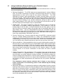
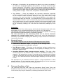
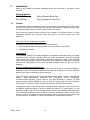
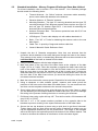
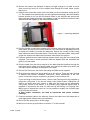
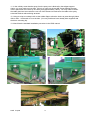
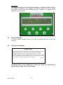
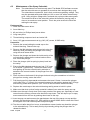
2.3
Installation - KRONE Big Pack Baler
Components:
There are a number of components that are specific to the Krone Big Pack installation;
870-Krone01-R01
RHS Support Frame
870-Krone02-R01
LHS Support Frame
870-Krone03-R01
RHS Long Bracket
870-Krone04-R01
LHS Long Bracket
870-Krone05-R01
RHS Short Bracket
870-Krone06-R01
LHS Short Bracket
4 sets of M10 x 30 hex head Bolts with M10 Nyloc nuts and flat washers.
4 M12 Nyloc nuts
870-E35-R01
Microwave cable assembly (1Yard longer than standard).
Overview:
This support system is attached to the two pairs of M12 bolts each side of the baler which secure
the tail gate in place. Two brackets for each side are supplied so that only one bolt at a time is
used to mount the Gazeeka support frame. In this way the tailgate is never left unsecured on one
side. The longer microwave cable is supplied to allow the cable assembly to be routed between
the two antennas using the existing structural cross member under the bale chute floor.
Procedure: (refer to photos below as well)
1.
Start on the left hand side of the baler (LHS facing forward). Loosen the front M12 nut and
put the LHS short bracket on the bolt and re-secure the new M12 nut making sure that the top of
the bracket is level (by using a small spirit level).
2.
Loosen the back nut and place the LHS long bracket over the bolt and tighten the new M12
nut only to the point where the bracket can still be swiveled around by hand.
3.
Place the LHS support frame in place and secure it to the two brackets using the two M10
bolts and nuts supplied. Tighten these up and then tighten the M12 tailgate nut up tight.
4.
Now, on the RHS, loosen the front M12 nut and put the RHS short bracket on the bolt and
re-secure the new M12 nut making sure that the top of the bracket is level (by using a small spirit
level).
5.
Loosen the back nut and place the RHS long bracket over the bolt and tighten the new M12
nut only to the point where the bracket can still be swiveled around by hand.
6.
Place the RHS support frame in place and secure it to the two brackets using the two M10
bolts and nuts supplied. Tighten these up and then tighten the M12 tailgate nut up tight.
7.
Place the active model 870S antenna (the one with the connector on it) in the LHS frame
and secure it in place using the M10 bolts supplied. Make sure the bolt heads are on the inside to
lower the chances of the chain snagging on an exposed bolt thread.
8.
Place the passive antenna in the RHS frame and secure it in place using the M10 bolts
supplied. Make sure the bolt heads are on the inside to lower the chances of the chain snagging
on an exposed bolt thread.
9.
Place the microwave cable assembly under the baler and present it to the antennas. Put
this cable assembly into each antenna as described in the model 870S manual. READ THE
MANUAL.
RHS Support Frame LHS Support Frame RHS long bracket LHS long bracket RHS short bracket
LHS short bracket
10. Securely cable tie the microwave cable from each antenna down to the main cross member
under the bale chamber floor, and along the back of the steel member.
870S V13p00
13