1
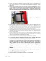
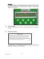
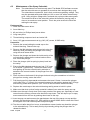
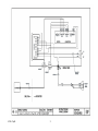
Operators Manual Moisture in Hay Bales Model 870S for Hay Balers V13.00 Feb. 2013 870S V13p00 blank 870S V13p00 2 IMPORTANT INFORMATION for your Model 870S This instrument (Model 870S) is calibrated for cured hay only. Not for uncured hay or silage. Conductivity meters will read differently, which will require the operator to gain experience comparing the 870S output to past methods to maximise the usefulness of the model 870S instrument. Please Note: With regard to the possibility of spontaneous combustion of hay, we can not tell you at what moisture you can safely bale hay at. The safe baling moisture level is dependent on many other factors including but not limited to the water soluble carbohydrate levels, microbial count, type and variety of plant, prevailing weather conditions and storage conditions. For information on determining the levels of the various factors that lead to spontaneous combustion of hay we suggest you contact you fodder peak body who should be able to assist you. The following information should be maintained in the event that you require support from the manufacturer. SERIAL NUMBER : A – Ratio : VMX - Offset : F1A - Offset : F1D - Offset : Date : Microwave module #: Software version: 00.0 This document is the property of International Stock Foods Inc. (trading under the name of Gazeeka) and may not be reproduced in whole or in part without the written consent of Gazeeka. 870S V13p00 3 blank 870S V13p00 4 1. INTRODUCTION......................................................................................................................................... 6 1.1 SYSTEM COMPONENTS ............................................................................................................................. 6 1.2 HOW IT WORKS........................................................................................................................................ 7 1.3 USING THE MOISTURE DATA PROVIDED BY YOUR GAZEEKA ANALYSER................................................. 8 Indemnity 1...................................................................................................................................................... 9 1.4 STANDARD OUTPUTS ............................................................................................................................... 9 1.5 TERMS AND CONDITIONS OF SALE ........................................................................................................... 9 2. INSTALLATION .........................................................................................................................................10 2.1 GENERAL ................................................................................................................................................10 Indemnity 2.....................................................................................................................................................10 2.2 STANDARD INSTALLATION – MASSEY FERGUSON/CHALLENGER/CASE-NEW HOLLAND ........................11 2.3 INSTALLATION - KRONE BIG PACK BALER ...........................................................................................13 2.4 INSTALLATION - EXTRA NOTES ..............................................................................................................15 2.5 ENVIRONMENTAL CONSIDERATIONS .......................................................................................................15 2.6 LICENSING ISSUES...................................................................................................................................15 2.7 COMMISSIONING / SETUP ........................................................................................................................16 2.8 PROGRAMMING GAZEEKA 870S BALE WIDTH ........................................................................................17 3. OPERATION ...............................................................................................................................................18 3.1 3.2 3.3 3.4 3.5 GENERAL INFORMATION .........................................................................................................................18 EDITING PARAMETERS USING THE KEYPAD ............................................................................................18 NORMAL OPERATION ..............................................................................................................................19 ALARM CONDITIONS ...............................................................................................................................20 CALIBRATION STANDARDS .....................................................................................................................20 4. SAFETY CONSIDERATIONS...................................................................................................................21 5. COMPLIANCE ISSUES .............................................................................................................................21 6. MAINTENANCE PROCEDURES.............................................................................................................22 6.1 6.2 6.3 7. CALIBRATION AND STANDARDISATION...................................................................................................22 AIR STANDARDISATION ..........................................................................................................................23 MAINTENANCE OF THE SPRAY SOLENOIDS .............................................................................................24 FAULT FINDING........................................................................................................................................25 8. TYPICAL SPECIFICATIONS 1,2...................................................................................................................26 APPENDICES ......................................................................................................................................................27 APPENDIX A – CONTROLLER PARAMETER LISTING AND ERROR CODES .............................................................27 APPENDIX B – STANDARD TERMS AND CONDITIONS ..........................................................................................29 870S V13p00 5 1. Introduction 1.1 System Components The Gazeeka Model 870S moisture monitor consist of the following components: Transmit Antenna - An active transmitting antenna containing microwave electronics to (1) generate and transmit the beam of microwave energy into the bale, and (2) receive and analyse the signal retuned from the receive antenna. Receive Antenna - A passive receiving antenna on the opposite side of the bale (ie. opposite the transmit antenna) which collects the microwave energy which has not been absorbed by the bale. The microwave antennae have been designed to optimise the moisture measurements in the baled fodder. Microwave Cable - A microwave cable (run inside a flexible steel conduit) which carries the collected microwave signal from the receiving antenna back to the electronics in the transmitting antenna for comparison with the originally transmitted signal. The microwave cable between the two antennae is an important part of the overall system and must be installed and maintained properly if optimal performance is to be achieved. There is more on this subject in the installation and maintenance chapters. Terminal (LCD Display/Keypad) – A liquid crystal display (LCD) unit with a keypad mounted in the driver’s cabin to enable control and measurement feedback. Antenna Support Frames – Used to mount the antennas onto the rear of the baler. Baler Cable (Interface Cable) - A cable to connect the transmit antenna to the Terminal in the tractor cabin. The power for the transmit antenna comes directly from the tractor via this cable. Marking Spray System – A paint spray marking system that is capable of automatically marking bales for easy identification at the pickup stage. Terminal in tractor Transmit Antenna Microwave Cable Marking Spray System Receive Antenna 870S V13p00 6 1.2 How it Works The Gazeeka Model 870S instrument uses microwave techniques to measure the moisture content of the hay in the bale as it emerges from the baler. Gazeeka instruments use techniques that are based on sound scientific principles, which have been proven in the laboratory and verified in the field. The instrument measures the speed of the microwaves and the amount of microwave energy absorbed through the bale of hay. The speed of microwaves through air is very close to the speed of light through space, and the speed of microwaves through dry hay is a little slower than through air. However, the speed of microwaves in water is considerably slower than that in dry hay. The difference in this speed is attributed to a value known as the dielectric constant (or sometimes called relative permittivity). The dielectric constant for air is close to 1, for dry fibrous material it is closer to 2 while for pure water it is approximately 80. Similarly, the amount of microwave energy absorbed in air is less than dry hay and in dry hay is much less than in water. Thus if measured correctly, these measurements can be a very sensitive method of measuring moisture in the bale of hay. The calibration of the Gazeeka moisture monitor was carried out without removing variable factors such as hay temperature, bale density and the way the bale was pressed to try and ensure that typical variations in these types of variables are within the precision parameters required in a reliable, real time, on-line hay moisture measurement system. Microwaves can "bounce" off stationary or moving metal objects and interfere with measurements, so the Gazeeka Model 870S System uses both hardware and software techniques to minimise the effect that these sources of "noise" may have on the operation of the instrument. Further information on how to obtain the best performance from the Gazeeka Model 870S moisture monitor can be found in the installation section. All of the microwave signals are generated using crystal locked frequency synthesisers. This means that there is no maintenance requirement to check operating frequencies for optimum moisture measurement performance. As a bale moves into the microwave beam, the system detects the change in microwave signal and determines a bale is present. The system then looks for small changes in the microwave signal to indicate that the bale is moving within a reasonable time allowance for a plunger stroke (if not it determines the bale has stopped). Then once the system determines that the bale is far enough past the microwave beam so that it can reasonably be expected that the entire detected microwave signal has traveled through the bale (and not some of the signal around the end of the bale) it starts to convert the microwave readings to a moisture content. In simple terms there are only three things that are critical to obtain a good moisture measurement, (assuming the microwaves are being measured correctly). These are a good air path reading, the bale width set properly, and the correct equation for the type of hay being baled is selected. The fist two items are close to "set and forget" once these are set they should not change from year to year unless the baler is changed or parts of the microwave system are replaced or moved. To ensure that your Gazeeka Model 870S instrument remains compliant in terms of electromagnetic emissions and electromagnetic susceptibility, the instructions and procedures in this manual are recommended to be followed. 870S V13p00 7 1.3 Using the Moisture Data provided by your Gazeeka Analyser. Understanding the limitations of the readings. Some of these points are reasonably obvious, but are documented here to clear up any misunderstanding : Moisture Distribution - The 870S antennae are approximately 8 inches (200mm) wide. The 870S is measuring an average1 moisture through the bale in a volume approximately as wide and as high as the antenna dimensions. The 870S calculates a moisture value approximately 10 times a second (about once every 100 milli seconds). Within each of these 100 milli second readings, thousands of microwave readings are made and many microwave readings are averaged to get the best moisture reading. If the moisture distribution along the bale is varying wildly (approximately 0.5%) within this short reading time as the bale moves by, then the output from the analyser may be unpredictable. Leading Bale - The trigger mechanism to start the readings is set up so that the 870S starts its microwave readings approximately 1 foot (300mm) in from the leading edge of the first bale. In normal situations this will only apply to the first bale out and the successive bales will generally abut the preceding bale with no gap between them. Like any electromagnetic signal the microwave signal will always take the easy path if it is available, so, if the readings are taken too close to the ends of the bale, the signal may go around the bale rather than through it, or some other unpredictable "end effects" may occur. Process Control Loop - If you are using the output of the 870S in a process control loop (for example adding preservative to a bale), the instantaneous moisture readings may vary too much for the process control system to track properly (over compensating or "hunting" may occur). In this case, use the time smoothed output (you can edit the time constant used) as the input into you process control loop. Moisture Additions - Moisture additions which are poorly distributed throughout the bale are likely to cause the 870S to give unpredictable results which may be higher or lower than the true average. There are a number reasons why this may occur. Just one reason why this may occur is if the readings that the 870S is taking as the bale moves along synchronize with either the low moisture bands or the high moisture bands, or an uneven combination of both which will cause a biased reading. Fodder Temperature -The temperature of the material under test should also be consistent within +/- 5 degrees Celsius (+/- 10 degrees Fahrenheit) to ensure that any bias taken out during calibration remains constant. The dielectric constant for moisture changes with temperature, however these changes are small compared to when the temperature is close to or beyond the freezing point or boiling point of the moisture at which temperatures the instrument will not provide reasonable readings. This instrument cannot measure moisture that is frozen or very close to frozen. Performance of conductivity probes is also affected by the freezing of the moisture. Microwave Distortions – Sometimes the leading or trailing edge of a bale or severe layering of high moisture sections within the bale can lead to microwave alternative paths and or resonance effects. Your Model 870S has been programmed to detect most (if not all) of these type of distortions which may effect the accuracy of the moisture reading. In these cases, the last reasonable moisture reading is held and the operator is alerted that an error has occurred. These errors are very transient and usually disappear within seconds. 870S V13p00 8 Bale gaps – Occasionally, the gap between two bales is very close to a multiple of the microwave wavelength (typically about 120mm - 5 inches) and extra signal energy is absorbed. This leads to a one off high moisture reading at the end of a bale. If this happens too often the problem can easily be resolved by shortening or lengthening the tail gate chains a small amount to change the gap between bales making smaller or larger. Please note, this problem is extremely rare. Hay Additives – Some hay additives are extremely conductive (especially propionic acid which unlike most additives, requires you to increase the dose rate as the moisture content increases, leading to very high does rates at high moistures.). We have found that for all the typical additives on the market, the recommended dose rate has little or no material effect on the performance of the Gazeeka 870S. However, if you over dose this may cause the conductivity to rise up to a point where you need to consider its effect on the moisture reading. High conductivity in hay caused by additives will affect the microwave readings as well as the conductivity readings, but it will affect the conductivity readings by much more. Indemnity 1 International Stock Foods. (the company which sells the Gazeeka brand) shall not be responsible for any consequential damage cause by the use of the analyzer. The Gazeeka instrument is an extra tool that should assist the operator in assessing and controlling the operational status of the baling operation. The values provided by the instrument should not be used to determine contractual or custody transfer issues. These issues should be determined by statistically representative sampling and laboratory assays carried out to national or international standards. 1.4 Standard Outputs The standard outputs from the Gazeeka 870S analyser are as follows: Instantaneous Moisture output - This gives you the average moisture reading over a preset analysis time (typically 5 seconds). Peak Moisture output - This gives you the maximum moisture reading over a preset number of instantaneous readings. This is typically 12 readings (12 x 5 = 60 seconds of analysis time). Smoothed Moisture Output (average moisture reading) - This gives a time smoothed output of the moisture from a number of Instantaneous readings. For example, if the analysis time is set to 5 seconds and the smoothing time constant is set to 120 seconds, then this output will give the average of the last 24 readings (120 / 5 = 24 ). Note that this time is the time spent analysing, not the real time on a clock. This description of the smoothed moisture output is a slight simplification of what actually happens. For the technical person, the smoothing time is the time based coefficient in a moving exponential smoothing algorithm. 1.5 Terms and Conditions of Sale This instrument has been sold under the International Stock Foods Terms and Conditions of Sale (Contract). If a copy of these Terms and Conditions of Sale are not in this manual, they may be obtained by contacting International Stock Foods. 870S V13p00 9 2. Installation Refer to the following Gazeeka Drawings which can be found in the back of this manual: 2.1 Drawing Number 870-E49-R00 Wiring Diagram Baler End 870-E50-R00 Wiring Diagram Tractor End General An installation which is properly carried out and takes into account all of the issues raised in this manual will minimise any risk that the moisture reading obtained from the Gazeeka Model 870S moisture monitor will be erroneous. Other than the specific issues raised in this chapter, the general issues of good installation practice and common sense still apply if the best results are to be obtained. General items not supplied by Gazeeka. Gazeeka's normal supply does not include the following: Electrical Noise filters or isolation that may be required on the vehicle. Lightening protection. Indemnity 2 The Gazeeka analyser has been designed to withstand reasonable levels of normal electrical "noise"; however, warranty does not cover any damage cause by electrical noise which may include electrostatic discharge, lightening strike, load dumping (disconnecting the battery whilst the alternator is still charging), welding etc. Gazeeka shall not be responsible for any consequential damage cause by the use of the analyser. Sources of Microwave Interference. The Gazeeka Model 870S moisture monitor uses low levels of microwave radiation. External sources of microwave radiation can affect the readings, as can the reflected signals from nearby microwave signal reflectors. There are many sources of microwave signals around in today's environment. Burglar alarms, data transmission systems, and microwave ovens, "Bluetooth" communications systems, just to name a few. Any Bluetooth or similar 2.4 GHz communication system should be kept at least 10 yards away from the Gazeeka 870S system. This may include cellular phones which are Bluetooth enabled. A large percentage of the human body consists of water. Anyone in the vicinity of the microwave measuring beam is likely to affect the results. For best results, no one should be within a yard of the microwave beam which travels between the antennae. This includes a yard behind each antenna as well as "around" the beam. Please note that this issue is not related to work place safety issues, as the microwave levels are so low; however, as always, it is best to minimise any unnecessary exposure. 870S V13p00 10 2.2 Standard Installation – Massey Ferguson/Challenger/Case-New Holland For Krone installation refer to section 2.3 in this manual. Your Gazeeka package should contain the following items: Transmit Antenna - An "Active" antenna, microwave cable assembly, and a control cable that attaches to the antenna. Receive Antenna - A "Passive" antenna. Mounting Brackets - Two type "A" mounting brackets and two type "B" mounting brackets. Each antenna support frame requires one type "A" and one type "B" bracket. Eight 3/8 x 1 inch bolts for attaching the antenna frames to these brackets. Antenna Protection Bars - Two antenna protection bars with 5/16” hex head screws (M8). LCD/Keypad - Tractor cabin display unit with cables attached to it. Bolts - Four 3/8” x 5” bolts for attaching the antenna units to the rear baler frame. Cable Ties - A quantity of large and medium cable ties. Owner's Manual & Quick Reference Card 1. Unpack the box of Gazeeka components. Note that one antenna has the connector which attaches to the cable that goes through the baler to the tractor. This antenna is the active (or transmitting) antenna and must be mounted on the Left Hand Side of the baler as viewed from the back. 2. Carry out this installation with the baler tailgate down. 3. Mark both sides of the rear side of the baler frame at the midpoint of the bale height (18" for a 3' bale). Place the template up against the baler frame with the hole in the middle of the template in line with the bale centre line you marked. Now you may have to move the template out a little to make sure it clears any weld fillets and you may have to move it up a little as some balers have a bolt on the front side of the baler frame where you would be drilling the holes for the microwave antenna brackets. 4. Mark the hole centers with a center punch. Repeat this for both sides of the baler. 5. Using a setsquare or other suitable system, measure and center punch the positions of the holes on the front side of the baler frame. You can mark one hole, and then use the template to determine the second hole position. 6. Some balers have electrical wiring going through the rear baler frame to which you are attaching the microwave antenna. Please make sure you do not damage this wiring in the process of drilling the holes or mounting the antennas. 7. Drill these holes using a pilot drill say 1/8". Then drill out with a 3/8 clearance drill (say 13/32" or 27/64"). 8. Use the 2' x 2" x 1/4" square washers provided on the opposite side to the brackets to prevent crushing in the square hollow section of the baler frame. 9. Secure the two top brackets in place using a spirit level to get them horizontal. Tighten these bolts up. Note there are two types of brackets so make sure you use the appropriate bracket as per the photo below. The flange of the brackets will be at the top for the top bracket and at the bottom for the bottom bracket. This is done to minimize the chances of interference to the microwave signal. 870S V13p00 11 10. Secure the bottom two brackets in place just tight enough to be able to move them around by hand. All of the bracket bolts through the baler frame require Nyloc nuts. 11. Hang the two antennas (active on the left side) on the top brackets using the 3/8” x 1” hex head screws provided (do not fully tightened this stage). Move the bottom bracket around to line up with the bottom holes in the antenna and secure this place with the remaining screws. Now tighten up the four antenna screws on each antenna and then tighten up the bottom bracket bolts. Figure 1 – Mounting Brackets 12. Run the flexible conduit that contains the microwave cable over the top of the rear baler frame and connect it into the antennae. You may need an adjustable wrench to tighten the conduit nut inside the antennae. Secure the conduit in place using large cable ties around the baler frame. Connect the microwave cable, taking care as per the special note about the microwave cable below this section. 13. Fasten a protection bar to each antenna support frame using the hex head screws supplied. The holes in these protection bars are tapped. Note the extended end goes up on both sides. 14. Run the cable from the active antenna to the baler draw bar position through the baler and secure using good quality cable ties. Secure the cable such that it will not make contact with any moving parts of the baler. 15. Secure the Terminal in the tractor cab using the RAM mount supplied. 16. Plug the power cable from the terminal into a 12V source. There are many brands of tractors with various "standard" connectors. Some modification of the 12V power connections may be required to get power to the moisture unit. If you are using a John Deere tractor, use the John Deere power plug supplied to supply the 12V power. If you are not using a John Deere tractor, change the JD plug to one which suits your tractor, or hard wire the power into an appropriate 12V power source in the tractor. If an Auxiliary plug (cigarette lighter plug) is supplied, it should only be used for initial set up and testing, not ongoing use. Many types of tractors are used, so it is not possible to supply one universal type of good quality connector. A poor power connection can lead to inaccurate and erratic moisture readings. 17. Connect the baler cable to the terminal. Secure this cable loom with cable ties or other appropriate cable securing mechanisms. 18. Do not put the spray cans in at this stage. 19. Move on to the set up procedures in section 2.7 of this manual. 870S V13p00 12 2.3 Installation - KRONE Big Pack Baler Components: There are a number of components that are specific to the Krone Big Pack installation; 870-Krone01-R01 RHS Support Frame 870-Krone02-R01 LHS Support Frame 870-Krone03-R01 RHS Long Bracket 870-Krone04-R01 LHS Long Bracket 870-Krone05-R01 RHS Short Bracket 870-Krone06-R01 LHS Short Bracket 4 sets of M10 x 30 hex head Bolts with M10 Nyloc nuts and flat washers. 4 M12 Nyloc nuts 870-E35-R01 Microwave cable assembly (1Yard longer than standard). Overview: This support system is attached to the two pairs of M12 bolts each side of the baler which secure the tail gate in place. Two brackets for each side are supplied so that only one bolt at a time is used to mount the Gazeeka support frame. In this way the tailgate is never left unsecured on one side. The longer microwave cable is supplied to allow the cable assembly to be routed between the two antennas using the existing structural cross member under the bale chute floor. Procedure: (refer to photos below as well) 1. Start on the left hand side of the baler (LHS facing forward). Loosen the front M12 nut and put the LHS short bracket on the bolt and re-secure the new M12 nut making sure that the top of the bracket is level (by using a small spirit level). 2. Loosen the back nut and place the LHS long bracket over the bolt and tighten the new M12 nut only to the point where the bracket can still be swiveled around by hand. 3. Place the LHS support frame in place and secure it to the two brackets using the two M10 bolts and nuts supplied. Tighten these up and then tighten the M12 tailgate nut up tight. 4. Now, on the RHS, loosen the front M12 nut and put the RHS short bracket on the bolt and re-secure the new M12 nut making sure that the top of the bracket is level (by using a small spirit level). 5. Loosen the back nut and place the RHS long bracket over the bolt and tighten the new M12 nut only to the point where the bracket can still be swiveled around by hand. 6. Place the RHS support frame in place and secure it to the two brackets using the two M10 bolts and nuts supplied. Tighten these up and then tighten the M12 tailgate nut up tight. 7. Place the active model 870S antenna (the one with the connector on it) in the LHS frame and secure it in place using the M10 bolts supplied. Make sure the bolt heads are on the inside to lower the chances of the chain snagging on an exposed bolt thread. 8. Place the passive antenna in the RHS frame and secure it in place using the M10 bolts supplied. Make sure the bolt heads are on the inside to lower the chances of the chain snagging on an exposed bolt thread. 9. Place the microwave cable assembly under the baler and present it to the antennas. Put this cable assembly into each antenna as described in the model 870S manual. READ THE MANUAL. RHS Support Frame LHS Support Frame RHS long bracket LHS long bracket RHS short bracket LHS short bracket 10. Securely cable tie the microwave cable from each antenna down to the main cross member under the bale chamber floor, and along the back of the steel member. 870S V13p00 13 11. In the unlikely event that the spray from the spray can is blocked by the tailgate support chains, you may need to move them. If this is so, take out the two M6 screws holding the spay units in place and move them up one hole pitch (approximately 70mm). You may need to loosen the cable gland and even take the cover off of the antenna to make sure the cable to the spray solenoids reaches without being stressed. 12. Using tin snips or a sharp knife cut the rubber flaps to allow the chains to pass through (About 45mm diam. + horizontal cut in to the hole. (You may find these have already been supplied with the Krone mounting kit). 13. Now follow the standard installation procedure in the 870S manual. 870S V13p00 14 2.4 Installation - Extra notes Notes on specific tractor 12V connections: A. John Deere: The Gazeeka model 870S comes supplied with a John Deere "Standard Connector" John Deere part no. RE67013. This has connections via the "B" (ground - black wire) and "C" (switched 12V - orange wire) pins. If your tractor is not a John Deere, then remove the plug and wire direct to a reliable 12V source. Special Note Of all the electrical issues, the microwave cables between the two antennae is the most critical. The microwave cable must always be enclosed in the conduit provided. Since we are measuring down in the Pico-seconds (a millionth of a millionth of a second) excessive cable movements can cause errors. The conduit should be securely tied or clamped to prevent any movement. If the cables are re-routed for any reason, a new "air reading" should be carried out. The microwave cable consists of an inner copper conductor surrounded by a dielectric material. Excessive bending of the cable will damage the dielectric and may cause inaccuracies in the moisture reading. These cables do not bend like normal electrical cables! The bending radius should be kept to greater than 6 inches. The microwave cables are pre cut to suit the conduit lengths supplied with the instruments to ensure the cables are correctly terminated. The tightening of the connectors on each end of each of the microwave cable is also critical. This should only be done with a proper SMA torque spanner (wrench) [Huber & Suhner part no. 74Z0-0-21/ ] to 100 Ncm. If no torque spanner is available, then tighten using ones fingers to a snug tightness, then tighten an extra 45 degrees (about an eighth of a turn) with a small wrench. This is a poor substitute for a torque spanner and could lead to sub-optimal performance. If in doubt, it is best to just tighten a much as you can with your fingers. 2.5 Environmental Considerations The Gazeeka Model 870S moisture monitor is rated IP55 (NEMA 4), which means that it is protected against the ingress of dust and moisture to a reasonable degree. The instrument is rated from zero to 55 degrees Centigrade. 2.6 Licensing Issues The Gazeeka model 870S moisture monitor operates at specific frequencies and such low power levels such that licensing is not required. 870S V13p00 15 2.7 Commissioning / Setup Commissioning (sometimes referred to as setup) commences with a physical inspection of the installation. The checks will include, but not be limited to the following: 1. Make sure all the mounting fasteners are tight and the antennas are rigidly mounted. (Note that any repositioning of the antennas will require a new air standardization to be carried out). 2. The horizontal center line of the antennas should be approximately at the same horizontal center line of the bales to be measured and any tailgate support mechanisms should not be in the line of the microwave beam. 3. All reasonable efforts need to have been made to minimize any interference to the microwave measurement signals. 4. All electrical cables correctly routed and terminated. 5. Power up the monitor in the tractor and check that the LCD display says "Analyze". 6. Press the F1 key and enter the correct parameters for your application. See the section on editing parameters and the parameter list in Appendix A to carry out this task. The following points cover some of these important parameters. 7. Make sure that the width of the bale (approximately to the nearest inch or so) to be measured is entered in the "Thickness" parameter in Inches (typically a 3 foot bale = 32 inches and a 4’ bale = 48 inches). (see Parameter Table and section 3.8 for more detail). 8. Select the correct equation for the type of hay you are baling (see Parameter Table). (You can do this later if you wish. See section 3.3 – Normal Operation to lean how this and other variables can be changed (edited) very simply by using the Field Key during normal Analyze mode). 9. If you want the Terminal unit to give an audible sound (Beep) and mark the bale if the moisture goes above a given moisture, then enter these values in the appropriate parameters (see Parameter Table). (You can do this later if you wish. See section 3.3 – Normal Operation to lean how this and other variables can be changed (edited) very simply by using the Field Key during normal Analyze mode). 10. The spray units will active when the high moisture beep goes off in the tractor cab Terminal. Note that the spray units can be tested at any time in the normal analysis mode by pressing the UP arrow on the keypad. 11. Please note that in normal operation, the system only draws just less than half an Amp, however when the spray solenoids operate, up to 7 Amps may be drawn for a short duration. Ensure that any fuse protections had the capability of this current draw. 12. After at least a 10-minute warm up period, initiate an Air measurement and ensure that no error conditions are displayed (Section 6.2). If error conditions are displayed, fault find and rectify the problem. Error conditions are listed at the end of Appendix A. 13. After the air reading is done and the parameters are set, the system is ready for use. Note, there are only 3 fundamental things that need to be done to give a reasonable moisture analysis. 1. Set the bale width correctly 2. Do an air reading 3. Select a calibration. 870S V13p00 (need only be done once for that baler) (this should last forever, but once a season is good) (choose between what you are baling) 16 2.8 Programming Gazeeka 870S bale Width Set the bale width of a 3x3 baler a. b. c. Press F1 key Press Menu key to display "Set Parameters", then continue to press the "Item" key until you get to the item saying “Width” When new, Gazeeka units are standardized to a 3 foot wide bale, the unit should show 32 inches. If the unit you are installing is on a 3 x 3 baler, and it is showing 32, then press Menu unit you get to “Setup”, then press F1 to go back to Analyze mode. If the unit is not set to 32, then follow the 3x4 procedure below, but set the value to 32. Set the bale width of a 3x4 baler a. b. c. Press F1 key Press Menu key to display "Set Parameters", then continue to press the "Item" key until you get to the item saying “Width” Use the Field key to move the cursor under each digit. Use the Up and Down keys to set the value to 48, then press Menu unit you get to “Setup”, then press F1 to go back to Analyze mode. . 870S V13p00 17 3. Operation 3.1 General Information The Gazeeka Model 870S always reports the moisture on a WB (as received) basis. Note that the instrument will cease to measure moisture whilst its parameters are being edited. 3.2 Editing Parameters using the Keypad The main interface between the Model 870S Moisture Monitor and the user is provided by a 7-key keypad, situated on the LCD display unit in the tractor cabin and labeled as follows. MENU ITEM F1 FIELD UP ENT DOWN The functions of these keys are as follows: MENU ITEM FIELD ENT Used to move through the Menus while in Setup Mode. Used to move through different items in each Menu Used to move the cursor across the field when editing values. Used to initiate some Item actions. F1 UP DOWN Used to move between modes at certain Items Used to increase the value being highlighted by the cursor. Used to decrease the value being highlighted by the cursor. Your Model 870S Moisture Monitor can be in one of only two operational modes: Setup Mode or Analyze Mode. When power is first applied to the Model 870S Moisture Monitor, the instrument automatically goes into Analyze Mode ready to measure moisture in a bale. In Analyze Mode, use the F1 key to select the Setup Mode. See Appendix A for the Menu structure, Item and Parameter listings. You use the [menu] key to move through the menu list and the [item] key to move through the items on each menu. (See Appendix A for a complete list). The Model 870S uses a 2 line, 16 character per line LCD display to allow you to view the Items in different Menus and their values. You may also use the keys to change some of the values, to allow the Model 870S to adjust to your conditions. 870S V13p00 18 3.3 Normal Operation The Gazeeka Model 870S moisture monitor has two modes called Setup and Analyze. Upon power up, if there are no faults found during power up tests, the instrument automatically goes into Analyze mode. In Analyze mode a moisture reading is taken within a programmable time after the bale detected input is activated. The LCD display will indicate that the instrument is in Analyze mode, and will display the current moisture value as the last instantaneous moisture value and the average moisture value: READING S19 LEG I 17.1 P 22.8 A 18.0 I is the Instantaneous Moisture at each reading P is the peak moisture for the averaging period A is the average moisture value for the averaging period Displaying current status The first 8 characters on the top line display the current status of the instrument. The Sxx (shown above set to S19) is the moisture value at which the terminal gives out a "beep" and the bale is marked by the spray cans. The last three characters on the top line display the equation being used to convert the microwave readings to moisture readings. There is a universal calibration equation which may be used at any time, but using the appropriate calibration equation for the type of hay you are baling will give the best results. The current calibrations are: UNI FES OAT LEG OMX (Universal 1) (Grass Hay) (Cereal Hay) (Legume Hay) (Oat Mix) Changing the spray point moisture and the calibration equation using the FIELD key. At any time, you may change the moisture value at which the spray cans operate. To do this, press the FIELD key and the cursor will move under the "S". Now use the UP or DOWN keys to change this value. Note that after 5 seconds of inactivity, the cursor will revert back to its home position. At any time you may also change the calibration equation for the type of hay you are baling. To do this, press the FIELD key twice and the cursor will move under the calibration equation selection area. Now use the UP and DOWN keys to change to the type of hay you are baling. Note that after 5 seconds of inactivity, the cursor will revert back to its home position. At any time when the cursor is in its home position, the UP key will mark the bale. Some operators like to use this facility to mark a bale for some special reason other than its moisture content. Please note that the "beep and Spray" moisture value and the calibration equation selection can also be done in the setup mode via the standard menu structure. Warm up. Please note that under normal environmental conditions it may take up to two minutes before the analyzer will be operating to its optimal performance. 870S V13p00 19 Setup Mode The Setup mode allows you to setup and standardize (air reading) the Model 870S to your specific conditions. The standard air reading should be done at regular maintenance intervals and after extended periods of operation (for example at the beginning of each season). 3.4 Alarm Conditions If a fault or alarm condition occurs, the LCD will indicate what type of fault has occurred. 3.5 Calibration Standards Please Note This instrument has been calibrated to read moisture with respect to oven dried samples using the American Society of Agricultural Engineers Standard ASAE S358.2 Dec99 "Moisture Measurement – Forages". If readings differ from another method used for contractual purposes, then any average difference (bias) should be taken into account by the operator when using the readings produced by this instrument. NB0509301 The Model 870S is only calibrated for cured hay. Using this instrument on uncured hay or silage is not recommended. 870S V13p00 20 4. Safety Considerations Microwave radiation Safety Considerations 2004. The power levels of the microwave signal being radiated from the Gazeeka moisture meter are in milli-Watts and do not constitute a health risk. However, if there is no need for anyone to be in the beam between the antennae when the unit is on, don't do it, as it is best not to be exposed to any more microwave radiation than is necessary, and moreover, the results from the instrument will become meaningless with any part of the human body in the microwave beam. For microwave radiation, the maximum occupational exposure set out by Standard AS2772.1 is 1mW/cm2. The average radiation level at the surface of the antenna is normally less than 0.0001mW/cm2 ( even less 5 cm away). This is 1000 times less than set out by the Australian standard. If during reading a moisture, the instrument finds that the combination of density and moisture is such that the bale is absorbing too much microwave energy for the signal to be reliably measured on the other side of the bale, the instrument will raise the power level to 0.05mW/cm2 for the duration of the analysis time only. All EMC tests have been carried out at this higher power level. For comparison only. In the USA and other places in the world, microwave ovens are limited to a maximum leakage of 5mW/cm2 at a distance of 5cm from the oven surface. Another example is of a well known brand of Cell Phone which has a RF Power Density of 3.0 mW/cm2 next to the antenna, and 1.2 mW/cm2 @ 5 cm from the antenna. 5. Compliance issues IMPORTANT NOTE. To ensure that the instrument maintains its electromagnetic compatibility and electrical safety rating, the physical and electrical arrangements and component choice must remain as the instrument was supplied. All interfacing to the control cabinet must be carried out as per the drawings supplied in this manual. Safety Compliance This instrument has be designed and tested where necessary to meet international standards for electrical safety. Environmental Protection Compliance (IP / NEMA rating) This instrument has be designed and tested where necessary to meet international standards for environmental protection. IMPORTANT NOTE. To ensure that the instrument maintains its environmental protection rating, any holes put in the outer skin of the control cabinet, or use of cable glands etc. must be properly sealed up before use. 870S V13p00 21 6. Maintenance Procedures Antenna alignment Antenna alignment should be regularly checked. The distance between each of the four corners should be the same +/- ¼ inch. Alignment offsets can be checked with a "straight edge". Note that if re-alignment was required, a new air standardization will be required to be carried out. Actual alignment is not as critical as the alignment remaining the same after an air path reading (air standardization) has been carried out. Microwave interference Examine the installation and its surrounding for microwave interference effects as described in the installation section and correct if necessary. Antenna Repairs Should any damage occur to a microwave antenna, please ensure that your Gazeeka agent is notified so that repairs can be carried out. The antennas are generally not repairable in the field. Instrument stability If any corrections or changes had to be made during maintenance, ensure that ”air standardization" is carried out to ensure there has been no drift in the calibration. All moisture readings are referred back to an air reference standard. Position of Links and switches Make sure all links and switches are in their correct positions. 6.1 Calibration and Standardisation The in-built calibration system is based on theoretical models that have been derived by Gazeeka and verified both in the laboratory and in the field on hay bales. All of the calibrations are referred back to the empty path air measurement. Thus, the empty path air measurement has an important role in maintaining the calibration accuracy. The Model 870S is only calibrated for cured hay. Using this instrument on uncured hay or silage is not recommended. Comparisons with other moisture measuring methods Sometimes other methods are used to measure the moisture of the bales. In some cases, different readings may be obtained using these methods. These "other" methods may not be as accurate as the Gazeeka method, but it may be the method upon which payments are made. In cases where you may want the Gazeeka reading to more closely reflect this "other" method of measurement (even if the "other" method is not as accurate) you may put an offset into the model 870S unit to match the other readings. For example, if the you believe the "other" reading is reading 2% higher than the Gazeeka unit you can raise the average readings of the Gazeeka unit by putting a value of 2 into the "Offset" parameter in the Gazeeka unit. Negative numbers can also be entered into the Offset parameter if required. 870S V13p00 22 6.2 Air Standardisation An "air standardization" must be carried out at the time of installation, and should also be carried out if there are any physical changes to the installation and at the start of each season. This operation is carried out as follows. 870S V13p00 Make sure the instrument has been on for at least 10 minutes. Make sure the air path between the antennae is clear (i.e. no bale or anything else). The end of the bale should be inside the rear end of the baler doors by at least a foot. Select the Setup Mode - If in Analyze Mode, press [F1] to select the Setup mode. Press [Item] to select the “ENT for Air Cal” item. Press [ENT] to select an air path reading to be carried out. Clear the air path and press [F1]. Press [ENT] to calibrate - it will take a few seconds. If no error message displayed, the air path standardization has been completed OK. Press [ENT] to go back to the Setup Menu. The instrument is now ready to start measuring bales again. 23 6.3 Maintenance of the Spray Solenoids Note: The solenoids are not continuously rated. The Model 870S software ensures that the solenoids are not operated for more than their designed duty cycle. The solenoids are marked 6V, that is their continuous operating voltage. They may be operated safely and reliably at 12V or even 24V with a reduced duty cycle. Using a higher voltage with a reduced duty cycle provides extra power. The maximum thrust of the solenoid is when the armature (moving part) is close to its maximum travel position. This is the point at which it should be making the can spray. Equipment list: 1. Small flat blade screw driver. 2. 3mm Allan key 3. #2 pozi drive (or Phillips head) screw driver. 4. Long nose pliers. 5. Thread locking compound such as Loctite 243. 6. 3mm (1/8") gap measurement rod (e.g. M3 (1/8") screw, 8 SWG wire) Procedure: 1. Remove the screw holding the metal cap on the solenoid housing. Remove the cap. 2. Remove the M4 stainless steel plunger bolt using the Allan key while preventing the plunger from turning using the small screw driver. 3. Remove the plunger and clean the inside cavity of the coil including in particular the conical section at the end. Clean the plunger. 4. Place the plunger (with its spring in place) back into the cavity. 5. Ensure the M4 stainless steel plunger has 5 "O"-rings on its shank (Type BS105). These are used to stop dust getting up into the solenoid cavity and also to determine the correct location of the plunger from the spray can. 6. Place Loctite on the thread of the plunger bolt and using the screwdriver to hold the plunger from turning, screw the bolt in. 7. Pull the plunger fully downwards and measure the travel. Screw / unscrew the plunger until it has 7mm (+/- 0.5mm) of movement between its rest position against the 5 O rings and the fully pulled down position. (Out 17mm at rest and 24mm when extended). 8. Replace the metal cap on the solenoid housing and 8g screw to hold it in place. 9. Make sure that dust or other foreign material is absent from under the spray can cap. 10. Make sure the cap is firmly down on the spay nozzle of the spray can, especially on new cans where the factory process often leaves the cap loose. This will require you to spay some material from the can by pushing down hard on the cap. 11. Insert a spray can and measure the gap between the top of the spray can cap and the plunger, this should be about 1/8". Use a drill bit or some 8SWG wire to check this. Bend the tongues of the can retainer plate to adjust this gap. 12. Test the unit after about four hours, as sometimes excess Loctite may bond the plunger to the solenoid body. This is easily feed up by manually pulling the plunger down to release the bond. 870S V13p00 24 7. Fault Finding As with most electronic equipment there are usually only two things that fail in the vast majority of cases. These are power supplies and electrical connections. Given this, these are the first two things to check if a fault is suspected. Check that the 12V dc supply is going to the microwave antenna and the LCD display. Connections can be checked with a meter, and by gentle movement of the wires, plug, connector or terminals. Depending on the fault conditions (symptoms), logic should tell you generally where to check. The third most common fault in instruments such as these is the "finger problem". Sometimes an instrument is left with a wrong value entered into the memory. This can be a particularly difficult problem, as often the wrong value which has been keyed in will only affect the results in a subtle way, and it is often some time before someone notices that the "results do not seem right". By this time the fact that the numbers were edited has been forgotten. The only solution is to re-check all the Parameters against the values as logged in the back of this manual. This is why it is important that whenever a change is made that the change is noted in the space provided in the parameter listing in this manual. Can not spraying correctly In some very dusty environments, dust may penetrate into the base of the solenoid plunger and prevent proper operation of the system. In this case, follow the above section on maintenance of the spray solenoids. 870S V13p00 25 8. Typical Specifications 1,2 PARAMETER UNITS VALUE Operational Moisture range Repeatability Precision Hay temperature % as received % moisture as received * % moisture as received * degrees Fahrenheit 1 to 25 0.3 0.7 50 to 110 * at one standard deviation * The Model 870S is only calibrated for cured hay. Using this instrument on uncured hay or silage is not recommended. Note the limits of operation in section 1.3. Environmental Protection Humidity Vibration Shock Temperature IP % relative humidity G's 10 to 100 Hz, 0.5mm G's 3 times in 3 directions degrees Fahrenheit IP55 (NEMA 4) 0 to 100 non condensing 0 to 2.5 5 32 to 115 Power Power Maximum disconnect voltage 6 Watts Volts ( 500 mA at 12V ) 30V (load dumping) (for 500 milli seconds) (no protection is provided for lightening strikes, welding excessive electrical noise etc.) Spray system. Solenoid current 2.8 Amps each (5.6A total) 30 seconds max at 12Volts Physical Connection John Deere part no. RE67013 Specifications subject to change without notice. 1 These are typical performance specifications for an ideal site, and may differ from any contractual agreement. 2 The calibration of this product is based on the homogeneous distribution of moisture (+/- half the quoted precision) within the material being measured, and industry best practice being used in the processing of the materials being measured. 870S V13p00 26 Appendices Appendix A – Controller Parameter Listing and Error Codes Menu Setup Menu Item Options Explanation Range Default Setting F1 for Analyse Enters the Analyse Mode N/A N/A ENT for Air Cal Press ENT to calibrate the instrument on an air path between antennae N/A N/A 0.0 to 100.0 30.0 N/A No Set Parameters Beep + Spray Low Moist Yes/No Equation Adds (or subtracts) any required bias (+ or - ) to the moisture readings Number of Analysis periods to hold a maximum reading (Peak Moisture) for. Analysis period is typically 5 seconds. Smoothing time constant (time in seconds that the average moisture value is averaged over) Offset Peak Hold Smoothing TC Width (units) Width ( in/m ) 870S V13p00 The Keyboard gives an audible alarm and operates the spray cans if the Instantaneous moisture goes over this value. Make this Yes if you are baling low moisture hay (less than 10%) and need more sensitivity to detect the bale's presence and movements. This does not change the calibration in any way. I.e. sometimes you are getting a "no bale" message when a bale is present, or "bale stopped" when a bale is moving. Selects the calibration equation to be used. 1 = Universal 1 (UNI) 4 = Legume Hay (LEG) 2 = Grass Hay (FES) 5 = Oat Mix (OMX) 3 = Cereal Hay (CER) in / m Universal 1 Fescue Hay Cereal hay Legume hay Oat Mix -99.99 to 99.99 Universal 1 00.00 0 to 99 12 1 to 1000 seconds 120 Units for the bale width (in = inches for USA) / (m = Metric) in Width of the bale (typically): 3 foot bale = 32 inches 4 foot bale = 48 inches 32 27 Record Your Settings Error Codes: Note: Some of the parameters in the Error codes table are only available to factory technicians and are not described in this manual. E1 LOW TEMP, HI TEMP - Temperature of the microwave board above or below its operational limits ► Switch off to cool down equipment. E2 DISTORTN (distortion) - Distortion in the microwave signal ► Microwave signal reflecting off a nearby object, or at end of bale. E3 LO APM (low microwave absorption) - Looks like you are trying to analyse an air path not a bale. ► Ensure a full bale is between the antennae. ( Or you may have done an Air Calibration whilst a bale was between the antennae which gives a false microwave reference level) E4 OV RANGE - Microwave attenuation too high ► Error in reading the microwave signal or moisture too high to read the signal. E5 CALCULATION ERROR - Unable to calculate moisture e.g. division by 0 or log(0) ► Wrong calibration equation, or poor choice of coefficients. E6 HI MOIST - Moisture out of limits ► Out of the calibration range of the instrument. Bale too high in moisture. E7 RESERVED - Not currently used E8 RESERVED - Not currently used E9 COMMUNICATION TIME OUT - Reply time out condition ► Check wiring connections between Antennas and Tractor display/keypad. EA AIR FALT (faulty air reading) - Tying to do an air reading without correct conditions ► Material in air path / or Antenna Alignment error ER DISTORTN (microwave distortion) - Distortion in the Attenuation spectrum ► Microwave signal reflecting off a nearby object, or at end of bale. Er DISTORTN (microwave distortion) - Distortion in the Group Delay spectrum. ► Microwave signal reflecting off a nearby object, or at end of bale. ssssssss = status which can be: START UP NO BALE BALE READING STOPPED BALE END OV RANGE HI MOIST DISTORTN LOW TEMP HI TEMP LO PHASE LO FPM LO APM AIR FALT 870S V13p00 (TA > TA Max ) (Moisture > Max Moisture) (ERMax or ErMax exceeded) (temp. below low limit) (temp. above high limit) ( TT+E2F < SDA ) ( FPM < FPM Min ( MUTA > MUTA Min) ( SDA < SDA Min or ( SDA > SDA Max or ( SAA < SAA Min or ( SAA > SAA Max ) 28 Appendix B – Standard Terms and Conditions STANDARD TERMS AND CONDITIONS OF CONTRACT International Stock Food Corporation (ISF) V1p1 V1p1 1. INTERPRETATION 1.1 "Articles" means all instruments, articles, materials or services supplied, or quoted to be supplied, by ISF to a Customer. 1.2 “Contract” means any contract entered into between ISF and a Customer for the supply of Articles. 1.3 "Customer" means the person, firm, company, authority or entity to whom ISF provides a quotation or from whom ISF accepts an order. 1.4 "ISF" means International Stock Food Corporation Inc. 2. TERMS 2.1 Unless varied in writing, these terms apply to every contract for the supply of Articles and prevail over any other terms proposed by the Customer at any time. 2.2 No agent or contractor of ISF may vary or add to these terms other than with the written consent and acknowledgement of ISF or make any representation about the performance, specifications or fitness for purpose of any Article other than as specified in authorized ISF manuals for the relevant Article. 3. PRICES AND VALIDITY 3.1 Prices quoted are valid for thirty (30) days from date of quotation but, prior to acceptance, are subject to change or withdrawal at any time by written notice. 3.2 All prices are firm and in US Dollars (USD) unless stated otherwise. 3.3 In the event that commissioning and calibration of Articles does not commence within six (6) months of delivery, price escalation may apply for engineering services required for those purposes. 3.4 If any government taxes or charges are payable on any supply made by ISF to the Customer then to the extent not otherwise specifically provided for in any quoted or agreed price the amount otherwise payable by the Customer will be increased by the amount of the government charge or tax. 4. TERMS OF PAYMENT 4.1 Terms of payment if not specified are ten (10) days net from date of invoice for Articles. 4.2 If payment is not made in full by the due date ISF will be entitled to charge interest on any amount outstanding at a rate 3% higher than the maximum rate charged by ISF’s bank in respect of an unsecured overdraft of such amount. 4.3 The Customer will not be entitled to deduct from any amount due any set off, counterclaim or other sum unless agreed in writing by ISF. 4.4 In the case of a Letter of Credit, operation of the Letter of Credit for Articles shall be the date of dispatch ex ISF works, Woodstock GA in accordance with INCOTERMS 2000. 5. RISK 5.1 All risks transfer to the Customer at the time of delivery. 6. TITLE 6.1 Transfer of title occurs once the Articles have been paid for in full. 6.2 Until payment in full: (a) the Customer shall hold the Articles as fiduciary bailee and agent for ISF; (b) unless otherwise notified in writing, the Customer is authorised to sell the Articles in the ordinary course of business; (c) after giving 48 hours notice to the Customer, ISF shall be entitled to enter the premises of the Customer between 9am and 5pm to inspect the Articles; (d) the Articles shall be stored separately and in a manner to enable them to be identified and cross-referenced to particular invoices; and (e) the proceeds of any Articles sold will held by the Customer on trust for ISF, and separate account and must not be mixed with any other moneys. 870S V13p00 29 must be in a 6.3 If payment for the Articles is not made by the due date ISF shall be entitled to enter the Customer’s premises at any time to do all things necessary in order to take possession of the Articles, without being liable for trespass, conversion or any resulting damage. The Customer shall be liable for all costs of whatsoever nature of and associated with the exercise of rights by ISF under this clause, which shall be payable on demand. 6.4 The Customer acknowledges that if the Articles are mixed with or incorporated into, other products or items such that the Articles are no longer separately identifiable, then ISF will be owner in common of the new product with the Customer. 7. DELIVERY DATE 7.1 The delivery date defined in a quotation or order acceptance from ISF is based on ISF factory demands at the time of the quotation or order acceptance. 7.2 The delivery date may be varied at the time of order based on ISF factory demands at time of order. 8. EXCUSABLE DELAY 8.1 In the event of any stoppage, delay or interruption of work or business related to the manufacture of Articles as a result of strikes, lockouts, trade disputes, breakdown, accident or delay in obtaining material inputs for equipment manufacture or any other cause beyond the control of ISF, the delivery date shall be extended (without claim by the Customer) by the duration of the delay. 8.2 The Customer is allowed a reasonable time to provide Customer supplied information. Excessive delays in providing information will result in the delivery date being extended by the duration of the delay and may result in re-negotiation of the delivery date in accordance with prevailing factory demands at that time. 8.3 Any delays beyond the control of ISF which impede the provision of engineering services during commissioning and calibration of Articles shall entitle ISF to extend the delivery date and all costs incurred by ISF as a result of such delays will be the responsibility of the Customer. 9. CONFIDENTIALITY 9.1 Any drawings, software or other information supplied by ISF is not to be passed to, or made accessible by third parties without prior written consent of ISF, and then only to use such information for the specific purpose for which consent is granted . 9.2 Copyright in all documentation in relation to Articles will remain vested in ISF and may not be used without the express written consent of ISF for any purpose other than by the Customer for the purposes for which it is furnished. 10. CERTIFICATION 10.1 Unless specifically notified by ISF in writing, the Customer acknowledges that: 11. (a) no Article is certified for assessment of commodities in relation to transfer of ownership or otherwise for measurement in the context of commercial transactions; and (b) Instruments supplied by ISF are an extra tool to be used in assessing plant performance trends and general operational status, and not for definitive or contractual determination of performance. (c) all performance indicators are at one standard deviation and exclude sampling and laboratory errors as generally determined by the use of the 'Grubbs Estimator" technique (see ASTM 6543). WARRANTY 11.1 ISF warrants the Articles will be free from encumbrance at the time of transfer to the Customer. 11.2 ISF warrants the Articles will be of the kind and quality described in the quotation under which they are sold and in any supplied operating manuals and that they will be of merchantable quality, free of defects in workmanship and material and be fit for purpose as described in the operating manuals. Except as provided in these terms or as required by mandatory operation of law, all conditions or warranties express or implied in respect of Articles are excluded. 11.3 Unless otherwise mutually agreed for special projects, the warranty period for equipment supplied shall be thirteen (13) months from date of delivery or twelve (12) months from date of commissioning whichever period expires first. Notification of faults believed by the Customer to be covered by warranty must be made in writing to ISF within thirty (30) days of discovery of the defective occurrence. 11.4 ISF does not accept responsibility for onsite damage, misuse of the Articles or use not in accordance with ISF operating manuals, guidelines or written instructions. 11.5 Warranties provided under these terms exclude deficiencies caused by compliance with Customer’s instructions, damage caused by misuse, neglect or any other operation or activity contrary to instructions for use. 870S V13p00 30 12. LIABILITY 12.1 Notwithstanding any other term or condition contained in any Contract, ISF will not be liable for or any losses, loss of income, loss of opportunity to earn profits, damages, compensation, costs and expenses, or for any indirect, incidental or consequential loss or damage resulting from or in any way related to a Contract (including delivery of Articles provided under a Contract) irrespective of the nature or cause of action, except where the liability of ISF cannot by law be excluded. 12.2 The liability of ISF to a Customer in respect of all other claims whatsoever is limited in aggregate to the payment by way of damages of a sum or sums not exceeding the total amount of price payable under the relevant Contract. 12.3 The provisions of this Clause 13 continue to apply notwithstanding fundamental breach, breach of fundamental term, revision, repudiation or termination for any reason or frustration, whether deliberate, unintentional or by operation of law. 13. ACCEPTANCE OF ORDER 13.1 All orders received by ISF are subject to acceptance by ISF. 14. TERMINATION 14.1 Following written notification of acceptance of an order by ISF the Customer may not suspend or terminate the order. 15. WAIVER OF REMEDIES 15.1 No forbearance, delay or indulgence by either party in enforcing the provisions of any Contract will prejudice or restrict the rights of that party nor will any waiver or its rights operate as a waiver of any subsequent breach and no right, power or remedy by the Contract conferred upon or reserved for either party is exclusive of any other right, power or remedy available to that party and each such right, power or remedy will be cumulative. 16. CONSEQUENTIAL DAMAGE 16.1 ISF shall not be held responsible for any consequential damage that may result from the use of Articles. 17. APPLICABLE LAW 17.1 These terms and any Contract between ISF and the Customer are governed by and will be construed in accordance with the laws of Georgia USA. 18. DISPUTES 18.1 ISF and the Customer must negotiate in good faith for a period of 21 days following receipt of a written notice of dispute (issued by either ISF or the Customer) to resolve the dispute detailed in such notice. 18.2 If the dispute is not resolved within that time, then at any time thereafter either ISF or the Customer may require the dispute to be referred for arbitration. The arbitrator will act as an expert and will determine the procedures for the arbitration. 18.3 The decision of the arbitrator will be final and binding. 18.4 The costs of the arbitrator will be borne equally unless otherwise directed by the arbitrator. 870S V13p00 31 870S V13p00 32 870S V13p00 33