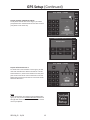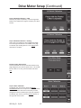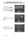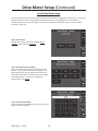
1
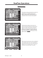
RowFlow
Operators Manual
955128_02 12/10
This Page Intentionally Left Blank
955128_02 12/10
2
Precision Planting, Inc.
23207 Townline Road
Tremont, IL 61568
ph. (309) 925-5050
fax. (309) 925-5029
[email protected]
[email protected]
Precision Planting Warranty & Liability Policy (Revision effective 7-1-10)
Warranties, Disclaimers, and Limitation of Remedies:
These terms and conditions represent the entire agreement between the parties hereto an there are no collateral,
oral, or other agreements or understandings, unless expressly stipulated.
Precision Planting warrants that all Precision Planting products, equipment and merchandise are free from defects
in material and workmanship. The term of the express warranty recited herein shall be limited to one (1) year from
the date of sale by Precision Planting. This warranty shall only extend to the dealer if this warranty is properly
presented to Customer. With respect to 20/20 SeedSense, AirForce and RowFlow, the express warranty recited
herein shall only apply if such products are properly registered by the Customer.
These terms and conditions represent the entire agreement between the parties hereto and there are no collateral,
oral, or other agreements or understandings, unless expressly stipulated.
The express warranty recited herein does not extend to any costs or damages other than one of the following,
which Precision Planting shall elect at its sole discretion: replacement, repair, or refund of the purchase price.
Precision Planting makes no other warranty of any kind whatsoever, express or implied.
ANY EXPRESS OR IMPLIED WARRANTIES OF MERCHANTABILITY OR FITNESS FOR A PARTICULAR PURPOSE ARE
HEREBY DISCLAIMED BY PRECISION PLANTING. THERE ARE NO WARRANTIES THAT EXTEND BEYOND THE
DESCRIPTION ON THE FACE HEREOF.
Precision Planting is NOT LIABLE FOR CONSEQUENTIAL DAMAGES of any nature whatsoever, including without
limitation lost yield, replanting cost, supplies or other expenses. Precision Planting is NOT LIABLE FOR INCIDENTAL DAMAGES of any nature whatsoever, including without limitation diagnostic and installation expenses, travel
expenses, and shipping expenses. The limitations of remedy recited herein apply to any action by the Customer
whether or not such action is based in warranty.
Some states or jurisdictions do not allow the exclusion or limitation of implied warranties, incidental damages or
consequential damages; so the above limitations or exclusions may not apply to you.
Liability:
Customer assumes all liability for damages from accidents caused by or incurred in the use of transportation of said
equipment. Customer agrees to indemnify and hold harmless the said Precision Planting, its officers, agents, and
employees from any and all damages and/or liability to any person whomsoever arising out of or resulting from the
use, storage, or transportation of said equipment by the Customer or anyone else while the equipment is in the
custody of the Customer. The Customer acknowledges receipt of the equipment in good working condition and
repair. In the event of any accident involving said equipment, Customer shall promptly furnish to Precision Planting
a complete report in writing, with names and addresses of witnesses and parties involved and Customer shall make
all reports required by law. Customer agrees to review and follow any published safety instructions in the product
manual.
Notice of Non-Waiver:
The failure by Precision Planting, at any one or more time, to insist upon the strict performance by the Customer of
the covenants, conditions and/or terms of this agreement, shall not be construed as a waiver of Precision Planting’s
right to demand strict compliance with and performance of all covenants, conditions and/or terms hereof. Notice
of demand for strict compliance is hereby waived by the Customer, and time is expressly made of the essence of
this agreement.
Choice of Law:
Any dispute or claim arising from or related to this Policy, or related to a product governed by this Policy, shall be
governed by the laws of the State of Illinois.
955128_02 12/10
3
Safety Information
Always wash your hands after working on or around agricultural equipment prior to
eating, drinking, smoking, chewing, etc…
Always use the proper Personal Protective Equipment (PPE) for any task.
Examples include: Gloves when handling sharp or abrasive materials
Eye protection when handling contents or systems under pressure (ie. Hydraulic, Pneumatic, Water)
Welding helmet, Welding gloves, and welders clothing when welding/
torching
Prior to working under or at ground level of any equipment secure the machinery from
movement; accidental user operation or simple rolling of equipment. This should
involve Lock-Out tags at the battery, removal of the Ignition key, “Do Not Operate” signs
placed at key locations, as well as wheel chocks as necessary.
When working on a vehicle or implement’s hydraulic system, suspended components
may suddenly drop. If you are working on or around the implement at this time serious
injury could result. If possible lower the implement or attachment to the ground
before beginning any work. Alternatively; use mechanical lock-up devices to secure any
components in their lifted positions.
Agricultural equipment may have been exposed to many types of chemicals. Any
chemicals or residues should be removed from the planter prior to beginning work.
Obey all existing (new & original) warning signs and caution labels on all equipment.
When working on or around equipment that has been or is running many components
may get extremely hot. To avoid injury &/or serious burns allow all equipment
components to properly cool before working on or around them.
Avoid wearing loose or ragged clothing or jewelry around equipment, with special
attention to avoid moving parts.
Route and secure all wires and connections to avoid crimping or damaging. This may
result in unexpected shortages and shocks.
Use extreme caution when working on pressurized systems (Air, Water, Oil). Relieve all
pressure from a system before disconnecting lines, fittings, etc… Use a cloth or other
obstruction to divert possible spray when disconnecting hose connections, fittings, fill
caps, breathers, etc. Always use gloves, NEVER use bare hands. To locate or check for
leaks use cardboard, never your hand.
Electrical components and devices may contain high voltages and should be kept dry
and closed. There are no serviceable components in this unit. Do not open this display
unit, the AirForce Module, Row Flow Module, or the Smart Connector. Opening of the
covers should be done by, or with guidance from trained personnel.
955128_02 12/10
4
Table of Contents
General
Legal & Safety.................................................................................................................................................. 2
System Requirements...................................................................................................................................... 3
Table of Contents............................................................................................................................................. 4
GPS Setup
Configuring your Planter............................................................................................................................... 7-9
Tractor Setup............................................................................................................................................ 10,11
Frame Type............................................................................................................................................... 11,12
Seed Exits.................................................................................................................................................. 12,13
GPS Setup Notes............................................................................................................................................ 14
Drive Motor Setup
PWM Drive Motor Setup.......................................................................................................................... 15,16
Lift Switch Calibration............................................................................................................................... 16,17
Primary Speed Source................................................................................................................................... 17
Motor Calibration..................................................................................................................................... 17,18
Radar Calibration........................................................................................................................................... 19
Serial Drive Motor Setup......................................................................................................................... 20-22
Swath Configuration
Control Style.................................................................................................................................................. 23
Calibration State............................................................................................................................................ 24
Swath Calibration.......................................................................................................................................... 25
Coverage Pattern........................................................................................................................................... 26
RowFlow Operations
Dashboard Screen......................................................................................................................................... 27
RowFlow Control Screen............................................................................................................................... 28
Variable Rate Control............................................................................................................................... 28,29
Loading a Prescription............................................................................................................................. 30,31
AutoMap Express.................................................................................................................................... 32,33
Swath Control......................................................................................................................................... 34,35
Boundaries.............................................................................................................................................. 35-39
Creating Simulated Headlands................................................................................................................ 39,40
Loading a Field Boundary.............................................................................................................................. 40
Diagrams
Wiring Diagrams...................................................................................................................................... 41-58
955128_02 12/10
5
This Page Intentionally Left Blank
955128_02 12/10
6
GPS Setup
Configuring your Planter
Step 1: Planter Setup
To configure your planter in the SeedSense screen, press
the SETUP button on the dashboard screen and then
select the PLANTER button in the top left of the Plant tab.
This screen shows each configuration that can be set for
your planter. The planter diagram at the bottom of the
screen will change to reflect changes you make in planter
setup.
Step 2: Planter Make
Press the PLANTER MAKE button. Choose the
appropriate make for your planter. Choosing the planter
make will define some of the choices available in later
selection screens.
Step 3: Number of Planter Rows
Press the ROWS button. Choose the number of rows
on your planter. Use the arrow at the right side of the
screen for more options. Under the selections for John
Deere, the DB options refer to the number of rows (i.e.
“DB48” refers to a 48 row Deere Bauer not a 48’ Bauer
bar). You will enter the total number of rows for your
planter and use the active rows feature to define which
ones are planting.
955128_02 12/10
7
GPS Setup (Continued)
Step 4: Row Spacing
Press the SPACING button. Choose the spacing for the
rows on your planter when all rows are planting. If the
appropriate spacing is not available, press OTHER to
manually enter the row spacing.
Step 5: Active Rows
Press the ACTIVE ROWS button. Define which planter
rows will be active. The system defaults to “All”. You may
also select from “Left”, “Right”, “Odd”, or “Even” primarily
for use on split row planters when only planting on half
your rows. You may also select “List” to define specific
rows that are planting or not planting, an application
primarily used when planting seed corn.
Step 6: Meter Type
Press the METER TYPE button. Select the type of meters
on your planter from the list. Pressing OTHER allows you
to type in a meter type if yours is not in the list provided.
Step 7: Drive Type
Press the DRIVE TYPE button. Select your planter drive
type from the list. Again, pressing OTHER allows you to
manually enter a drive type.
955128_02 12/10
8
GPS Setup (Continued)
Step 8: Down Force System
Press the DOWN FORCE SYSTEM button. Select your
down force system from the list or press OTHER to
manually enter a different option. Note: The selection
“Dual Factory Airbags” refers to the original John Deere
pneumatic down force system which used two smaller
bags side-by-side for down pressure.
Step 9: Lift Force System
After you have selected your down force system, select
your Lift Force System.
Step 10: Effective Row Spacing and Effective Planter
Width
These values are automatically calculated based on row
width, number of rows, and active rows. They can be
manually changed by pressing the button and entering a
new value.
Step 11: GPS Setup
Press the GPS SETUP button on the right side of the
screen.
955128_02 12/10
9
GPS Setup (Continued)
Step 12: GPS Setup – Tractor
Press the TRACTOR button. This screen allows you to
enter measurements on your tractor so that the
SeedSense can more accurately display your
coverage map. Entering your TRACTOR MAKE and
TRACTOR MODEL provide useful troubleshooting
information. Press each button to enter the information.
At this time, FRONT is the only steering option available.
Step 13: Pivot Offset
Press the PIVOT button. Measure the distance from
the rear axle of the tractor to the pivot point. Enter the
distance in inches (or centimeters if the display is set to
Metric units). Press ENTER.
Step 14: Center Offset
Press the CENTER button. Measure the distance to the
right or left of the center line of the tractor from your
GPS antenna and enter it. Use the flip button to change
the orientation of the measurement from right to left.
If the antenna is exactly on the center, enter “0”. Press
ENTER.
Step 15: Forward Offset
Press the FORWARD button. Measure the distance from
the rear axle of the tractor to the location of the GPS
antenna and enter it. Press ENTER.
955128_02 12/10
10
GPS Setup (Continued)
Step 16: Height Offset
Press the HEIGHT button. Measure the distance from the
ground to the GPS antenna and enter it. Press ENTER to
return to the Tractor setup screen, verify your entries,
and then press ENTER to return to the GPS Setup
Selection screen.
Step 17: GPS Setup - Planter - with “Single” frame type
Press the PLANTER button. This screen allows you to
enter measurements on your planter so that the
SeedSense can more accurately display your coverage
map.
Step 18: Frame Type
Press the FRAME TYPE button in the top left corner.
Select the frame type that best fits your planter.
Step 19: Hitch Style
Press the HITCH STYLE button in the top right corner.
Select the hitch style that best fits your planter.
955128_02 12/10
11
GPS Setup (Continued)
Step 20: Planter – with “Dual Rear” frame type
Now you will measure and enter measurement values
for your planter. Depending on the frame type selected,
there may be as few as two measurements to enter or as
many as five.
Step 21: Wheel Distance
Press the WHEEL DISTANCE button. With the planter
lowered, measure the distance from the pivot point to
the lift wheels. Enter the value. Press ENTER.
Step 22: Seed Exit 1
Press the SEED EXIT 1 button. Measure the distance from
the pivot point to the seed tube exit for all rows (if frame
type is “Single”) or for the forward most set of rows (for
all other frame types. Enter the value and press ENTER.
Step 23: Seed Exit 1 Rows
For all planter frames other than “Single” you will need to
define which planter rows correspond to this
measurement. Select from the options available or press
LIST to choose specific rows manually.
955128_02 12/10
12
GPS Setup (Continued)
Step 24: Seed Exit 2 & Seed Exit 2 Rows
For all planter frames other than “Single” you will be
prompted to enter measurements for the other rows on
your planter in the same way.
Step 25: Off Center Distance 1
For “Dual Front” and “Dual Rear” frame types, you will
now enter the off center distance of each bar. For Off
Center Distance 1, measure the distance from the pivot
point to the center of the rows on the front set of rows.
Repeat the measurement for the rear set of rows under
Off Center Distance 2.
NOTE:
If your planter does not conform to the available frame
types, you may use the CUSTOM TABLE SETUP button on
the right side of the screen to enter the location of each
row on your planter.
955128_02 12/10
13
GPS Setup Notes
955128_02 12/10
14
Drive Motor Setup
The 20/20 RowFlow system can, with one RowFlow Module (RFM), control three PWM hydraulic motors. To
control more than three motors, a second RFM will be needed. To configure your PWM hydraulic motors, go to
the RowFlow setup page. From the dashboard screen, press SETUP, then select the SYSTEMS tab, and then press
the ROWFLOW button on the control side of the page. At the top of the RowFlow Setup screen, press the MOTOR
CONFIGURATION button.
PWM Drive Motor Setup
The Drive Motor Setup screen includes all of the information related to configuring your drive motors. Up to three
PWM Drive Motors can be configured OR two serial drive motors can be configured. For information on
configuring serial drive motors, see page 20.
Step 1: Control State
To begin drive motor setup, press the black DRIVE
MOTOR 1 button and select ENABLED.
Step 2: Select Rows Driven by Motor
Next, select which planter rows will be driven by Motor
1. This may be All, Odd, Even, Left, Right, or List. When
selecting List, you will define which rows are not
controlled by this motor by touching those row numbers
so that they have an “X” over them. When done
selecting rows, press ENTER.
Step 3: Select Motor Brand
Now select the brand of the hydraulic motor being
controlled by pressing the appropriate button.
955128_02 12/10
15
Drive Motor Setup (Continued)
Step 4: Select Seeds per Meter Revolution
On this screen, select the number of seeds planted
per revolution of the meter. If your metering system
has a different number than any of the listed choices,
press CUSTOM and enter the appropriate number. For
instance, if using a six finger meter, enter “6” under
Custom.
Step 5: Default Population
Finally, enter your default population. This is the
population that the motors will plant when operating in
an area without a prescribed population to be planted.
Step 6: Confirm Configuration
Now confirm the configuration of Drive Motor 1 by
reviewing the settings displayed on the Drive Motor 1
button.
Note: Repeat Steps 1 – 6 for any additional motors.
Step 7: Lift Switch Calibration - Lowered
To begin calibrating your lift switch, press the LIFT
SWITCH button in the top left corner of the Drive
Motor Setup page. Make sure that your planter is
lowered completely. Press the large black button in the
middle of the screen to calculate your Lowered Percent.
955128_02 12/10
16
Drive Motor Setup (Continued)
Step 8: Lift Switch Calibration – Lifted
Now lift your planter completely. Press the large black
button in the middle of the page to calculate your Lifted
Percent.
Step 9: Lift Switch Calibration – Planting
Lastly, lower your planter to drive engagement height.
Press the large black button in the middle of the page
to calculate your Planting Percent. Press ENTER when
calibration is complete.
Step 10: Primary Speed Source
The second button at the top of the Drive Motor Setup
page designates your primary speed source. This should
be set to GPS. If it is not, press the button and select
GPS.
Step 11: Motor Calibration
To calibrate your drive motors, press the MOTOR
CALIBRATION button at the top of the Drive Motor Setup
screen. This screen will list the motors that you have
configured as well as a default gear ratio and stop delay.
To calibrate your motors, press the RUN CAL button on
the right side of the screen.
955128_02 12/10
17
Drive Motor Setup (Continued)
Step 12: Prepare to Plant
In order to calibrate your motors, you will need to ensure
that you have hydraulic pressure to your motor(s), seed
(at least 200) in at least four rows for each motor (for
example, if you have two motors, you will need seed
in a total of eight rows, four rows for each motor), and
vacuum on, if applicable. It is important to note that
calibration must be done with a singulated crop, like
corn. Results will be inaccurate with a non-singulated
crop such as soybeans.
Step 13: Calibrating Motors
Before proceeding, ensure that the driveline is clear and
that no one is working near the motors, driveline, or
meters. To calibrate, lift and hold the Auto-Load switches
as shown on the screen to start the process.
Step 14: Calibration Complete
Once calibration is complete, you will be shown the
calibration values for each motor that is configured and
the bottom of the screen will indicate that Calibration is
Complete. If you have more than three motors (using a
second RowFlow Module), press the MORE MOTORS
button on the right side of the screen and repeat the
process with those motors. Press ENTER when finished
to return to the Drive Motor Setup screen.
955128_02 12/10
18
Drive Motor Setup (Continued)
Step 15: Radar Calibration
To calibrate your radar, press the RADAR STATE button
in the top right hand corner of the Drive Motor Setup
screen. To calibrate the radar, you will need to be able to
drive the tractor straight forward at a speed of 4mph or
greater for up to 300 feet. You will need good GPS
reception during the entire calibration. When ready,
begin driving and press the black BEGIN CALIBRATION
button in the middle of the screen.
Step 16: Calibrating
While calibration is in process, you will be updated on
your distance traveled at the bottom of the screen. If you
need to cancel the calibration and start over, press the
CANCEL button.
Step 17: Calibration Complete
When calibration is complete, your radar calibration, in
pulses per foot, will be displayed. Press ENTER to return
to the Drive Motor Setup screen. Your drive motors are
now configured, calibrated, and ready for use.
955128_02 12/10
19
Drive Motor Setup (Continued)
Serial Drive Motor Setup
The Drive Motor Setup screen includes all of the information related to configuring your drive motors. Up to three
PWM Drive Motors can be configured OR two serial drive motors can be configured. For information on
configuring PWM drive motors, see page 15. At this time, only Rawson serial drive motors with an AccuRate
controller can be used.
Step 1: Control State
To begin drive motor setup, press the black SERIAL
MOTOR 1 button and select ENABLED.
Step 2: Select Rows Driven by Motor
Next, select which planter rows will be driven by Serial
Motor 1. This may be All, Odd, Even, Left, Right, or List.
When selecting List, you will define which rows are not
controlled by this motor by touching those row numbers
so that they have an “X” over them. When done
selecting rows, press ENTER.
Step 3: Enter Base Population
Now, enter the base population that you selected on your
Rawson AccuRate controller.
955128_02 12/10
20
Drive Motor Setup (Continued)
Step 4: Select Incremental Change
Enter the incremental change that has been entered into
your AccuRate controller – 2%, 4%, or 6.67%.
Step 5: Confirm Configuration
Now confirm the configuration of Serial Motor 1 by
reviewing the settings displayed on the Serial Motor 1
button.
Note: Repeat Steps 1 – 5 for any additional motors.
Step 6: Lift Switch Calibration
When controlling Rawson drives through an AccuRate
controller, a lift switch is not needed in the RowFlow
system. The lift switch in the Rawson system continues
to provide information to the AccuRate controller for lift
state.
Step 7: Primary Speed Source
The second button at the top of the Drive Motor Setup
page designates your primary speed source. This should
be set to GPS. If it is not, press the button and select
GPS.
955128_02 12/10
21
Drive Motor Setup (Continued)
Step 8: Motor Calibration
When controlling Rawson drives through an AccuRate
controller, calibration is done through the AccuRate.
Step 9: Radar Calibration
To calibrate your radar, press the RADAR STATE button
in the top right hand corner of the Drive Motor Setup
screen. To calibrate the radar, you will need to be able to
drive the tractor straight forward at a speed of 4mph or
greater for up to 300 feet. You will need good GPS
reception during the entire calibration. When ready,
begin driving and press the black BEGIN CALIBRATION
button in the middle of the screen.
Step 10: Calibrating
While calibration is in process, you will be updated on
your distance traveled at the bottom of the screen. If you
need to cancel the calibration and start over, press the
CANCEL button.
Step 11: Calibration Complete
When calibration is complete, your radar calibration, in
pulses per foot, will be displayed. Press ENTER to return
to the Drive Motor Setup screen. Your drive motors are
now configured, calibrated, and ready for use.
955128_02 12/10
22
Swath Configuration
The 20/20 RowFlow system can, with one RowFlow Module (RFM), control up to twenty-four (24) swath outputs.
These outputs can control individual rows or combinations of rows depending on the type of clutches and other
operational considerations. To control more than twenty-four swath outputs, a second RFM will be needed. To
configure your swath sections, go to the RowFlow setup page. From the dashboard screen, press SETUP, then
select the SYSTEMS tab, and then press the ROWFLOW button on the control side of the page. At the top of the
RowFlow Setup screen, press the SWATH CONFIGURATION button.
Step 1: Control Style
To begin configuring your swath sections, you will need
to select your control style. Press the CONTROL STYLE
button in the top left corner of the Swath Section Setup
Screen.
Step 2: Swath Control Style
Now select the control style for your swath system.
Choose from DISABLED if you want no swath control,
ROW CLUTCHES if you have a clutch on each row,
DRIVELINE DISCONNECTS if you have a half-width or
other width disconnect on the driveline, or HYDRAULIC
DRIVE SHUT-OFF if you will use your hydraulic drives for
swath control. If you choose, hydraulic drive shut-offs,
you will need to configure your drive motors before
continuing to configure your swath control.
Step 3a: Swath Clutch Style
If you select Row Clutches, you will then need to select
the type of clutch that will be controlled. Choose AIR
CLUTCHES for Tru-Count Pneumatic clutches. Choose one
of the electric clutch options depending on the harness
used. For harnesses from John Deere and Precision
Planting as well as Ag Leader harnesses which provide
single row control, select the larger black button on the
right. An Ag Leader Dual Row Harness refers to a
harness that controls pairs of rows across the planter.
An Ag Leader Dual Ends Harness refers to a harness that
controls the two rows on each end as a single unit but
controls the other rows in between individually.
955128_02 12/10
23
Swath Configuration (Continued)
Step 3b: Swath Disconnect Style
If you select Driveline Disconnects, you will need to select
which type of harness you are using to control those
disconnects. Determine whether you are using the 3
Output Harness (Precision Planting part number 727103)
or the Relay Module Harness (Precision Planting part
number 727115) and select the appropriate button.
Step 4: Number of Sections
Now press the NUMBER OF SECTIONS button in the top
row. Select the number of swath sections that you will
be controlling. If you selected Hydraulic Drive Shutoffs
as your control style, the number of sections will default
to the number of configured drive motors and cannot be
changed.
Step 5: Assigning Rows to Sections
Now you will need to assign rows to sections. You may
use the arrow to the left or right of number of rows to set
the number of rows in that section. This will also begin
to auto-fill row numbers in the “Rows in Section” column.
If the row numbers assigned to the section are not
correct, you may press the black box with the row
numbers in it. This will bring up a list of all rows and you
can select which rows are in this section by touching any
rows not in the section so that they appear with an “X”
over them.
Step 6: Calibration State
Next, you will need to calibrate your swath control. Press
the CALIBRATION STATE button at the top of the Swath
Section Setup screen. On this screen, you can set the
auto calibrate feature to “On” or “Off” by pressing the
TIMING CALIBRATION STATE button. Leaving this “On”
will allow the system to update the start and stop delays
as you plant.
955128_02 12/10
24
Swath Configuration (Continued)
Step 7: Swath Calibration
To perform the initial calibration, press the RUN CAL
button on the right side of the Swath Calibration screen.
To calibrate, you will need to be planting: hex shaft
turning and 300 seeds in at least four hoppers plus
vacuum on and air tank for clutches filled if applicable.
Press the PRESS TO CONTINUE button.
Step 8: Swath Calibration
Before proceeding, ensure that the driveline is clear and
that no one is working near the motors, driveline, or
meters. To calibrate, lift and hold the Auto-Load switches
as shown on the screen to start the process.
Step 9: Calibration Complete
Once the calibration is complete, note the start and stop
delays as well as the delay variation. Press ENTER when
you are finished. Press ENTER again to return to the
Swath Section Setup screen.
955128_02 12/10
25
Swath Configuration (Continued)
Step 10: Coverage Pattern - Offset
Finally, you will need to define your coverage pattern.
This defines how you want the clutches to operate when
entering and leaving already-planted areas. All Swath
Control methods setups will require you to choose an
offset from the left side of the screen. Choosing NO
OFFSET directs the swath control to plant right up to the
line of seeds previously planted. ½ ROW OFFSET will
control clutches to plant to within a one-half row-width
of the previously planted seeds. If you are using a 30”
row planter, this will leave a 15” gap. Selecting 1 ROW
OFFSET will leave a full row-width gap.
Step 11: Coverage Pattern – Under/Over Plant
If you are controlling individual rows, the selections on
the right side will not be available. If, however, you are
using individual row clutches but controlling them in
multiple row sections, you will have to select one of the
options on the right side of the screen. This determines
when the multiple row section shuts off when it comes to
the offset point chosen at left while at an angle.
Choosing UNDERPLANT means that the section will shut
off when the first row in the section hits the offset point.
Choosing OVERPLANT will shut off the section when the
last row in the section hits the offset point. Choosing
50%-50% means that the section will shut off when the
middle of the section hits the offset point. Press ENTER
when you are done.
Step 12: Confirm Setup
Your Swath Sections are now configured. Press ENTER
again to return to the RowFlow Setup screen.
A diagram on this screen will show your planter as
configured including which rows are controlled by which
motors and swath sections. Verify that your setup is
correct.
955128_02 12/10
26
RowFlow Operations
Dashboard Screen
The Variable Rate Seeding and Swath Control functions of
20/20 RowFlow are controlled through the 20/20
SeedSense monitor. When a RowFlow module is
detected, a RowFlow button is automatically added to
the dashboard screen to the left of the Setup button.
The RowFlow button displays the status of the two
functions of RowFlow, Variable Rate and Swath Control.
A green box indicates that he feature is detected and
configured. A yellow box indicates that the feature is
detected but not configured. A grey box indicates that
the function is not detected. In addition to displaying
status, pressing the ROWFLOW button takes you to the
RowFlow control screen.
When the Swath Control function is active, the dashboard
mini chart (DMC) shows which rows are tied together in
common swath sections with a series of boxes below the
population bars on the Population DMC. In this case, a
16 row planter is setup with eight 2-row sections.
955128_02 12/10
27
RowFlow Operations (Continued)
RowFlow Control Screen
In addition to pressing the ROWFLOW button on the
Dashboard screen, you can also access the RowFlow
control screen by pressing SETUP on the Dashboard
screen, then selecting the “Systems” tab, and then
selecting the “RowFlow” button under “Control”.
The RowFlow Control screen is the central location for all
variable rate and swath control features in the SeedSense
display. The center of the screen displays a coverage map
with current population, singulation, and spacing values
displayed below the map. The Population dashboard
mini chart is displayed at the bottom of the screen for
reference in both variable rate and swath control
operations.
Variable Rate Control
Variable Rate control is located on the left side of the
screen. The status button at the top indicates whether
Variable Rate control is “Enabled” or “Manual”. Pressing
this button enables and disables Variable Rate control.
Below the status button, the current population is
displayed along with the next population in the
prescription.
955128_02 12/10
28
RowFlow Operations (Continued)
Pressing the VARIABLE RATE button switches the system
to manual control. This ignores the prescription and
continues to plant at the population being planted at the
time the system disables. To control population again
based on the variable rate prescription, press the
VARIABLE RATE button. This returns the variable rate
status to “Enabled”.
When variable rate control is in “Manual”, the planter
continues to populate at the population being planted
when it was disabled. To change populations manually,
you can either select one of up to eight preset
populations (set on the “Population” screen under the
“Plant” tab) or you can adjust the population up or down
in 500 seed increments using the arrows on the left side
of the screen.
To change the value in the population adjust buttons,
select the DISPLAY button under the SYSTEMS tab. Press
the QUICK ADJUST button and select new value.
955128_02 12/10
29
RowFlow Operations (Continued)
Loading a Prescription
Variable Rate Seeding Prescriptions for 20/20 RowFlow can be generated in many computer programs including
AutoMap from Precision Planting, MapShots EasiSuite, FarmWorks, AgLeader SMS, APEX, and other programs that
can export a prescription as a shape file. At this time, only variable rate seeding prescriptions are supported by
20/20 RowFlow. Many prescriptions may be stored in the memory of the Display Unit. Each field can have one
active prescription at a time. Prescriptions may also be created using AutoMap Express in the SeedSense display.
Instructions for using AutoMap Express begin on page 32 of this manual.
To Import prescription files into the SeedSense display
unit, load the files onto a USB flash drive and insert the
drive into the display unit. From the dashboard screen
select SETUP, then the DATA tab, and then IMPORT. On
the Data Import screen, press PRESCRIP/BOUNDARY. This
will import both prescription and boundary files into the
display unit.
To load a prescription file for a particular field, go to
the Field Setup screen for that field. To get to the Field
Setup screen from the dashboard, press SETUP, then the
FIELD button, and then select the appropriate field. Press
the PRESCRIPTION button near the bottom right of the
screen.
955128_02 12/10
30
RowFlow Operations (Continued)
Select the prescription that you would like to load for this
field from the list. You may need to use the up and down
arrows on the right side of the screen to scroll through
the list to find the desired prescription.
Next, select SINGLE ATTRIBUTE or SPECIFIC ATTRIBUTE
PER MOTOR at the bottom of the screen, select the
desired attribute, and press ENTER. Repeat if applying
specific attributes per motor.
Once you have selected the prescription, verify on the
Field Setup screen that the correct prescription is loaded
by looking at both the PRESCRIPTION button and the
picture of the field to the left.
955128_02 12/10
31
RowFlow Operations (Continued)
AutoMap Express
AutoMap Express is a feature within the 20/20 display unit that allows you to generate variable rate seeding
prescriptions while in the field. To use AutoMap express, you will need to plant around the outside edge of your
field or have an RTK-quality boundary. Either of these will allow AutoMap Express to load the USDA soil map data
for the field and generate a field map.
To enter AutoMap Express, go to the RowFlow control
page and press the “AutoMap Express” button on the
right side of the screen. Once you have planted a pass
around the outside of your fields (or loaded a boundary
map) you will see the closed field map on your screen.
Once you have a closed field map, insert a USB drive with
the data needed and press “Get USDA Soil Map for Field”.
You may also choose to get the “USDA Soil Map for Field”
before you have closed coverage. If you do, it will
generate a map based on the farthest extents of the area
you have planted.
Once the soil map loads (this process may take up to
two minutes), you will be able to see the different soil
types both on the map and on the corresponding colored
buttons on the right. The name of the soil type will be
displayed below the population on each soil type
button. The number displayed is the CPI (Crop
Productivity Index).
955128_02 12/10
32
RowFlow Operations (Continued)
To set a population for a particular soil type, press the soil
type button and it will be highlighted in yellow. Adjust
the population up or down from the base population in
500 seed increments using the arrows at the bottom left
hand side of the screen. As you adjust the population of
a soil type, the average population value at the top of the
screen increases or decreases to reflect the changes.
To adjust the target population of all soil types together,
press the “Select All Soil Types” button. All soil types will
now be highlighted. You can now adjust the target
populations of all soil types at the same time using the
arrows at the bottom left of the screen.
To change the value in the population adjust button,
select the DISPLAY button unt the SYSTEMS tab. Press
the QUICK ADJUST POPULATION button and select a new
value.
Once you have set the populations of each soil type,
press the “Save Rx to Field” button on the right side of
the screen. This saves the prescription to the active field
and takes you to the Field Setup screen. You are now
ready to continue planting the field.
955128_02 12/10
33
RowFlow Operations (Continued)
Swath Control
Swath Control is located on the right side and lower part
of the screen. The status button at the top
indicates whether Swath Control is “Enabled” or
“Manual”. Pressing this button enables and disables
Swath Control. Swath Control switches to manual when
you press the status button or when you press one of the
arrow buttons at the bottom of the screen.
Once Swath Control is in manual mode, you now have
two methods for manual control. If you want to shut off
sections beginning on one end of the planter and moving
across, press the arrow under either “Clutch from Right”
or “Clutch from Left”. Each time you press an arrow it
will shut off or turn on one section. You may also select
“Manual Section Control”.
When you press MANUAL SECTION CONTROL, a new
screen will display with your clutch sections. Press a
section to shut it off. The text on the button will turn
grey with and X on it to indicate that it is shut off. Press
the down arrow to get to other sections.
955128_02 12/10
34
RowFlow Operations (Continued)
The “Control Plan” button allows you to define the
features to which your clutches respond. There are four
options. You can control to all four, to only one, or to any
combination of the four. Pressing one of the options in
the center of the screen will disable it as a control
feature. The title will turn grey with a line through it.
Once you have selected your control plan, press the
“Save Control Plan” button.
There are four features to which Swath Control will
respond. Selecting “Field Boundary” or “Inner Boundary
indicates that you want your sections to shut off when
outside of the field boundary or inside an inner
boundary. Selecting “Map Coverage” indicates that
you want the clutches to shut off when crossing into an
already planted area. Selecting “Simulated Headlands”
controls clutches to an offset from your field boundaries
to enable headlands to be planted last.
Boundaries and Simulated Headlands
Pressing the “Advanced Swath Control” button on the
RowFlow Control screen gives access to two Advanced
Swath Tools. These tools should only be used with RTK
quality GPS to ensure accurate performance. Using
poorer quality GPS can result in drifting boundaries and
inaccurate clutch control.
955128_02 12/10
35
RowFlow Operations (Continued)
Pressing the BOUNDARY button takes you to the Record
Swath Boundaries screen. Boundaries recorded are for
Swath Control only. They do not play a role in variable
rate seeding except that they can be used in AutoMap
Express to generate a soil map.
Before recording a boundary, you will need to enter a
Recording Offset Point. Press the SETUP OFFSET button
on the Record Swath Boundaries page (see above). Now,
enter the distance from the GPS unit to where you would
like the boundary line to be recorded. If the you are
recording to the opposite side of the vehicle, press the
FLIP button. When done, press ENTER to return to the
recording screen.
To begin recording, press the RECORD FIELD
BOUNDARY button (see above). As you drive the
boundary, it will be displayed on the screen. Press the
PAUSE button to pause recording (such as when turning
a corner) and CANCEL to cancel the recording. If you are
planting while recording, you may press HOME to see the
dashboard screen.
955128_02 12/10
36
RowFlow Operations (Continued)
Pressing the BOUNDARY button takes you to the Record
Swath Boundaries screen. Boundaries recorded are for
Swath Control only. They do not play a role in variable
rate seeding except that they can be used in AutoMap
Express to generate a soil map.
Before recording a boundary, you will need to enter a
Recording Offset Point. Press the SETUP OFFSET button
on the Record Swath Boundaries page (see above). Now,
enter the distance from the GPS unit to where you would
like the boundary line to be recorded. If the you are
recording to the opposite side of the vehicle, press the
FLIP button. When done, press ENTER to return to the
recording screen.
To begin recording, press the RECORD FIELD
BOUNDARY button (see above). As you drive the
boundary, it will be displayed on the screen. Press the
PAUSE button to pause recording (such as when turning
a corner) and CANCEL to cancel the recording. If you are
planting while recording, you may press HOME to see the
dashboard screen.
955128_02 12/10
37
RowFlow Operations (Continued)
If planting while recording a boundary, the black button
below the speed indicator will indicate your recording
status. Pressing this button will return you to the Record
Swath Boundaries screen.
Once your boundary comes within one offset-width of
the starting point, you will be prompted to either close
the boundary or continue recording. This completes the
recording of the field boundary.
You may now choose to record an additional Field
Boundary using the same process. This must be a
boundary applying to the same field.
955128_02 12/10
38
RowFlow Operations (Continued)
Once a Field Boundary is complete, you may record inner
boundaries within the field to designate no-plant areas.
Press the RECORD INNER BOUNDARY button to begin and
END INNER BOUNDARY to complete the boundary. You
may pause or cancel this recording if needed. When you
press PAUSE that button will become RESUME.
As you record the boundary, it is automatically recorded
in the list of boundary files unless you press CANCEL
RECORDING before it is complete. When you have
finished a set of boundaries for a field, you may press
HOME or BACK to leave this page.
Creating Simulated Headlands
Pressing the HEADLANDS button on the Advanced Swath
Tools page brings you to the Simulated Headlands screen.
If you wish to plant your headlands last, you can use this
feature to offset your field boundary, generating
simulated headlands where your clutches will turn off as
though you had already planted there.
955128_02 12/10
39
RowFlow Operations (Continued)
To create a simulated headland, you first need to
designate the width of the headland you would like to
create. Press the HEADLAND WIDTH button and enter
the desired width, in feet. Now, you can press the
CREATE FIELD BOUNDARY HEADLAND and/or the CREATE
INNER BOUNDARY HEADLAND buttons to create a
simulated headlands. To remove the simulated
headlands, press the buttons which are now labeled
REMOVE.
Loading a Field Boundary
Swath boundaries for 20/20 RowFlow can be generated in many computer programs including MapShots EasiSuite,
FarmWorks, AgLeader SMS, APEX, and other programs that can export a boundary as a shape file. Many
boundary files may be stored in the memory of the Display Unit. Each field can have only one active boundary at a
time. Boundaries may also be created using the Record Boundary feature in the SeedSense display unit as
described in the preceding pages.
To Import boundary files into the SeedSense display unit,
load the files onto a USB flash drive and insert the drive
into the display unit. From the dashboard screen select
SETUP, then the DATA tab, and then IMPORT. On the
Data Import screen, press PRESCRIP/BOUNDARY. This
will import both prescription and boundary files into the
display unit.
To load a boundary file for a particular field, go to the
Field Setup screen for that field. To get to the Field Setup
screen from the dashboard, press SETUP, then the FIELD
button, and then select the appropriate field. Press the
BOUNDARY FILE button near the bottom right of the
screen.
955128_02 12/10
40
955128_02 12/10
41
955128_02 12/10
42
955128_02 12/10
43
955128_02 12/10
44
955128_02 12/10
45
955128_02 12/10
46
955128_02 12/10
47
955128_02 12/10
48
955128_02 12/10
49
955128_02 12/10
50
955128_02 12/10
51
955128_02 12/10
52
955128_02 12/10
53
955128_02 12/10
54
955128_02 12/10
55
955128_02 12/10
56
955128_02 12/10
57
955128_02 12/10
58