1
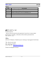
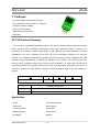
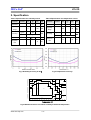
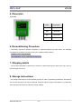
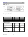
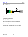
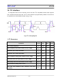
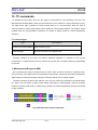
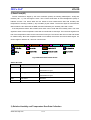
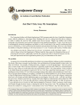
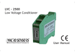
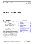
MiCo SnP
HT-01D
HT-01D
Humidity & Temperature
Sensor Module
User’s Manual
MiCo SnP
www.micosnp.com
1/16
MiCo SnP
HT-01D
History
Date
2013-03-30
Description
Initial Release. (Manual Integration)
2013-08-06 Addition output voltage table
2014-02-27 Interface circuit(Fig.10) and I2C address(Fig.12)
© MiCo SnP Co., Ltd.
All rights reserved.
No part of this document may be reproduced in any form or by any means,
photocopying, recording, or otherwise, without written permission from
MiCo SnP Co., Ltd.
Office
456-833, 53, Mosan-ro, Daedeok-myeon, Anseong-si, Gyeonggi-do, South Korea
TEL : (82)-(31)-612-6130
FAX : (82)-(31)-612-6212
Home-Page URL : http://www.micosnp.com
Printed in the Republic of Korea
www.micosnp.com
2/16
MiCo SnP
HT-01D
1. Features
- On-Chip humidity & temperature sensors
2
- Fully calibrated, various output (I C, Voltage)
- Excellent long-term stability
- Low power consumption
2
- Serial interface control (I C)
- Small size
HT-01D Product Summary
The HT-01D is a humidity & temperature sensor. The device includes a relative capacitive humidity
sensor elements and a band-gap temperature sensor with capacitive-to-voltage converter (C-V
Converter). This results in superior signal quality, a fast response time and insensitivity to external
disturbances at a very competitive price. Each HT-01D is individually calibrated in a precision
chamber. The calibration coefficients are programmed into the memory. These coefficients are used
internally during measurements to calibrate the signals from the sensors. The serial interface and
internal voltage regulation allows easy and fast system integration. Its small size and low power
consumption makes it the ultimate choice for even the most demanding applications. The device is
supplied in single-in-line type devices. Customer specific packaging options may be available on
request.
HT
-
①
01
(D)
②
③
①
Humidity-Temperature
②
Product Number
③
Pin Type (D)
Application
- HVAC
- Test & Measurement
- Automotive
- Data Logging
- Consumer Goods
- Automation
- Weather Stations
- White Goods
- Humidifiers
- Medical
www.micosnp.com
3/16
MiCo SnP
HT-01D
2. Specification
Table.1 Specification for humidity sensor
Parameter
Condition
min
typ
Resolution
max
Table.2 Specification for temperature sensor
Units
Parameter
bit
Resolution
14
Operating
Condition
min
typ
max
14
Units
Bit
Operating
0
100
%RH
-40
Range
120
˚C
Range
Typical
±2.5
Accuracy
%RH
Maximal
See figure 1,3
<±1.5
Hysteresis
Typical
±0.5
Maximal
See figure 2
˚C
Accuracy
%RH
Response
15
Response
10
25
time
sec
time
Fig.1 Humidity-accuracy at 25℃
100
±7
Relative Humidity (%RH)
90
Fig.2 Temperature-accuracy.
±6
±6
±8
±11
±9
±10
85
80
±5
±9
75
70
±8
65
60
55
±3.5
±4
±4
±6
50
45
40
±7
±5
±5
35
30
25
±6
±5
20
±8
10
±6
±7
0
5
15
20
25
30
35
40
45
50
55
60
65
70
75
80
85
Temperature (℃)
Fig.3 Maximal tolerance of relative humidity at different temperature
www.micosnp.com
4/16
sec
MiCo SnP
HT-01D
3. Reliability of Humidity Sensor
1) Normal operating Range
The sensor works stable within recommended normal range(see Figure. 3). Long term exposures to
conditions outside normal range, especially at humidity >80%RH, may temporarily offset the RH
Relative humidity (%RH)
signal. After return to normal range it will slowly return towards calibration state by itself.
100
80
60
Normal Range
40
20
0
-40
-20
0
20
40
60
80
100
120
Temperature (°C)
Fig.4 Normal operating range.
2) Hysteresis of Characteristics
The graph shows the hysteresis curve of HT-01D sensor. Considering the relative humidity of the
sensor, the hysteresis formula is give by
Hysteresis Value = H(10%RH → 90%RH) – H(90%RH → 10%RH)
The hysteresis variety of samples indicate △H
< ±1.5%RH at each humidity point. This result
shows that the sensor satisfies our specification. The meter is set to measure humidity value at VDD=5V. For the precise measurement, we used the hygrometer and compared with the humidity of
temperature-humidity chamber.
16000
DEC
Humidity value (DEC)
14000
12000
10000
8000
6000
4000
2000
0
0
10
20
30
40
50
60
70
80
Humidity(%RH)
Humidity
(%RH)
Fig.5 Hysteresis of Humidity Sensor
www.micosnp.com
5/16
90
100
MiCo SnP
HT-01D
4. Dimension
1) HT-01D
Name
Pin Function
VSS
Ground
SDA
Serial Data
SCL
Serial Clock
VDD
DC Power
6. Reconditioning Procedure
The sensor exposed to extreme conditions or chemical solvents may have offset. The following
reconditioning procedure may bring back to the calibrated state of device.
• Baking : 100 ˚C for 8 hours
• Re-Hydration : 25˚C, >80 %RH for 48 hours
7. Shipping details
HT-01D was packaged in plastic trays. Please be careful opening from side of the tray cover to
avoid damage of sensors.
8. Storage instructions
The storage instructions must be followed precisely in order to guarantee specification. Guarantees
are one-year storage of the sensor package. Chemical vapors at high concentration in combination
with long exposure times may offset the sensor reading.
www.micosnp.com
6/16
MiCo SnP
HT-01D
9. Block Diagram
Fig.9 HT-01D Block diagram
10. Operating Condition
1) Absolute Maximum Ratings
Parameter
Symbol
Min
Analog Supply Voltage
VDD
Voltages at Analog I/O In Pin
Typ
Max
Units
-0.3
6.0
V
VINA
-0.3
VDD+0.3
V
Voltages at Analog I/O Out Pin
VOUTA
-0.3
VDD+0.3
V
Storage Temperature Range
TSTOR
-55
150
˚C
Symbol
Min
Typ
Max
Units
VSUPPLY
2.3
5
5.5
V
TAMP
-40
125
˚C
CVSUPPLY
100
470
nF
CVCORE
10
110
nF
I C Pull-up Resistor
RPU
1
10
kΩ
SDA Load Capacitance
CSDA
0.2
nF
3
μA
2) Operating Conditions
Parameter
Supply Voltage to GND
Ambient Temperature Range
External Capacitance between VDD pin
and GND
External Capacitance between VCORE
pin and GND
2
Current
www.micosnp.com
Digital output
Isleep
7/16
220
2.2
1
MiCo SnP
HT-01D
11. Circuit Interface
VDD
Rp
Rp
1~10K?
Csupply
0.1uF
VDD
MCU
SDA
SCL
GND
2
Fig.10 HT-01D I C Interface
1) Power
The HT-01D requires a voltage supply between 2.3 and 5.5V. After power on, the device needs
10ms to reach measurement state. No commands should be sent. If you send command at that time,
you cannot receive correct data from sensors.
2) Serial Clock (SCL)
The SCLK is used to synchronize the communication between a microcontroller and the HT-01D.
Since the interface consists of fully static logic there is no minimum SCL frequency.
3) Serial Data (SDA)
The SDA pin is used to transfer data in and out of the device. Data changes after the falling edge
and is valid on the rising edge of the serial clock SCL. During transmission the SDAT line must remain
stable while SCL is high. An external pull-up resistor is required to pull the signal high.
www.micosnp.com
8/16
MiCo SnP
HT-01D
12. I2C Interface
2
For integration with the micro-controller, the HT-01D has a I C-compatible interface which supports
2
both 100 kHz and 400 kHz bit rate. The I C slave address is programmed by default on 28H and can
be adjusted in the entire address range of (00H to 7FH).
2
Fig.11 I C Timing Diagram
1) I2C Parameters
Parameter
Symbol
Min
Max
Units
fSCL
100
400
kHz
tHDSTA
0.1
ms
Minimum SCL clock low width
tLOW
0.6
ms
Minimum SCL clock high width
tHIGH
0.6
ms
Start condition setup time relative to SCL edge
tSUSTA
0.1
ms
Data hold time on SDA relative to SCL edge
tHDDAT
0
ms
Data setup time on SDA relative to SCL edge
tSUDAT
0.1
ms
Stop condition setup time on SCL
tSUSTO
0.1
ms
tBUS
1
ms
SCL clock frequency
Start condition hold time relative to SCL edge
Bus free time between stop condition and start
condition
www.micosnp.com
9/16
MiCo SnP
HT-01D
13. I2C commands
As detailed in below table, there are two types of commands for user operating a HT-01D. The
Measurement Request (MR) is wake up command sent by the master for a new measurement cycle.
2
The Data Fetch (DF) command is used to fetch data in I C communication. With the start of
communication the entire output packet will be loaded in a serial output register. The register will be
updated after the communication is finished. The output is always scaled to 14-bits programmed
resolution.
2
I C command types
Type
Descriptions
Measurement Request(MR)
Start measuring cycle
Data Fetch(DF)
Used to fetch data in any digital mode
Humidity modules do not carry out internal arithmetic operation to minimize on the current
consumption. A measurement process is carried out only after the command measuring request (MR)
is received.
1) Measurement Requests (MR)
By a measurement request command, the HT-01D is woke up and it executes a measuring cycle.
The measuring cycle begins with the temperature measurement, followed by humidity measurement,
digital signal processing and finally writing the measured values into the output register.
The MR command consists of the address of the HT-01D, with which the R/W bit is transferred as
0(= write). The real signal of MR is 0x50 adding write bit(0) to address(0x28). After the humidity
module is answered with ACK (= measurement started), the master finalized the transfer with NACK
(=stop condition).
Fig.12 Measurement Request Command
www.micosnp.com
10/16
MiCo SnP
HT-01D
2) Data Fetch(DF)
The DF command is began by the micro-controller (master) as sending address(7bit : 0x28) and
read bit (1bit : 1). The real signal is 0x51. The HT-01D sends back an acknowledgement (ACK) to
indicate success. The others data are two status bit and measurement data with humidity and
temperature to sending a NACK (= stop condition) by the master. The first two bytes of measurement
data contain the two status bits as MSB, and then followed by the humidity value with 14 bits.
If the temperature data is also needed, then these can be read after the humidity value. The most
significant 8 bits of the temperature value will be transferred as third byte. Then the least significant 6
bits of the temperature value can be read as the fourth byte. The last two bits are not used and should
be masked away. But if the temperature data is not needed, the master can send a NACK signal. If it
doesn’t appear “state bit 00”, does not communicate.
Start
Start
Read
Write
Device Address[6:0]
Read ACK State Humi. Data[13:8] ACK
Start Condition
ACK
Acknowledge
Read = 1
Write = 0
State
Status Bit (2bit)
Humi. Data[7:0] ACK Temp. Data[15:0] ACK
Cap. Data
Temp. Data
Humidity Data Bit
Temperature Data Bit
Temp. Data[7:2] NACK Stop
NACK Not Acknowledge
Stop
Stop Condition
Fig.13 Measurement Packet Reads
Status Bit Table
Status Bits
Output
Definition
00B
Clipped normal output
Data that has not been fetched since the last
measurement cycle.
01B
Not applicable
Data that has already been fetched since the last
measurement cycle.
10B
Not used
Not used
11B
Not used
Not used
3) Relative Humidity and Temperature Raw Data Collection
www.micosnp.com
11/16
MiCo SnP
HT-01D
Raw data are collected for the HT-01D. The Raw data should also be the average of several
samples to minimize noise effects. To collect relative humidity and temperature raw data in
measurement, the expression as follows;
The Humidity_High and Humidity_Low bytes can be read in %.
14
Humidity [%RH] = (Humidity_High[5:0] × 256 + Humidity_Low[7:0] )/2 × 100
The Temp_High and the Temp_Low bytes can be read as temperature output in ºC.
14
Temp output [C] = (Temp_High[7:0] × 64 + Temp_Low[7:2]/4])/2 × 165 - 40
Using bit range [MSB:LSB]
www.micosnp.com
12/16